Effect of Non-linearity of Connecting Dampers on Vibration Control of Connected Building Structures
 Masatoshi Kasagi
 Kohei Fujita
 Masaaki Tsuji
 Izuru Takewaki
- Department of Architecture and Architectural Engineering, Graduate School of Engineering, Kyoto University, Kyoto, Japan
The connection of two building structures with dampers is one of the effective vibration control systems. In this vibration control system, both buildings have to possess different vibration properties in order to provide a higher vibration reduction performance. In addition to such condition of different vibration properties of both buildings, the connecting dampers also play an important role in the vibration control mechanism. In this paper, the effect of non-linearity of connecting dampers on the vibration control of connected building structures is investigated in detail. A high-damping rubber damper and an oil damper with and without relief mechanism are treated. It is shown that while the high-damping rubber damper is effective in a rather small deformation level, the linear oil damper is effective in a relatively large deformation level. It is further shown that while the oil dampers reduce the response in the same phase as the case without dampers, the high-damping rubber dampers change the phase. The merit is that the high-damping rubber can reduce the damper deformation and keep the sufficient space between both buildings. This can mitigate the risk of building pounding.
Introduction
The connection of multiple building structures with dampers is one of the effective vibration control systems (for example, Iwanami et al., 1996; Luco and de Barros, 1998). In the case where these building structures have different natural frequencies, each building disturbs the vibration of other building structures. Furthermore, it can be assumed that the properties of connecting dampers affect strongly the performance of vibration reduction of such connected building structures. It appears therefore useful to investigate the effect of the non-linear properties of connecting dampers on the vibration reduction mechanisms of connected building structures.
A high-damping rubber damper (Tani et al., 2009) and an oil damper with and without relief mechanism (Soong and Dargush, 1997; Hanson and Soong, 2001) are treated in this paper. The high-damping rubber dampers have a high performance of energy absorption for a cyclic loading and possess not only the large elastic–plastic deformation capacity like metallic hysteretic dampers but also the sufficient amount of viscous damping capacity (see Tani et al., 2009). Especially the large deformation capacity (almost 300% shear deformation) and the extremely large performance for accumulated plastic deformation are two major advantages over other dampers. On the other hand, the relief mechanism is usually adopted in the oil dampers in order to decrease the force applied to surrounding structural members.
As for the vibration control of buildings with connecting dampers, Iwanami et al. (1996) investigated the optimal quantity of connecting elements (stiffness and damping). This theory is well known as “Fixed-Point Theory.” In this method, the stiffness of the connecting element is used for adjusting the heights of the fixed points, and the minimum transmissibility has been achieved by the damping of the connecting element. Luco and de Barros (1998) derived an optimal interconnecting element location in the connected building system. Takewaki (2007, 2015) and Fukumuto and Takewaki (2015) introduced the energy approach in the design of buildings with the connecting damper system in which the energy transfer function plays a key role for assessing the effectiveness of the connecting dampers. Cimellaro and Lopez-Garcia (2011) studied the optimal damper distribution in the buildings with a connecting damper system. Patel and Jangid (2011) investigated the response of two buildings connected by friction dampers. Richardson et al. (2013a,b) developed a closed-form expression of the optimal connecting dampers, which minimize the absolute displacement transmissibility.
It is shown in this paper that while the high-damping rubber damper is effective in a rather small deformation level, the oil damper is effective in a relatively large deformation level. Furthermore, it will be remarked that the response velocity in the oil dampers is too large compared to the limit value specifically in low-rise buildings and careful attention should be paid in their installation to low-rise buildings.
Modeling of Non-Linear Dampers and Connected Building Structures
Modeling of Non-Linear Dampers
The oil damper used in this paper obeys the following damper force fv – relative velocity relation as shown in Figure 1.
where κ denotes the ratio of the post-relief damping coefficient to the initial value cv and ηV,c is the damping force at 0 velocity in the post-relief relation. When the velocity attains the specific value , the relief mechanism works and goes into the second branch. An example of the damping force–relative displacement relation of an oil damper without and with the relief mechanism is shown in Figure 2A.
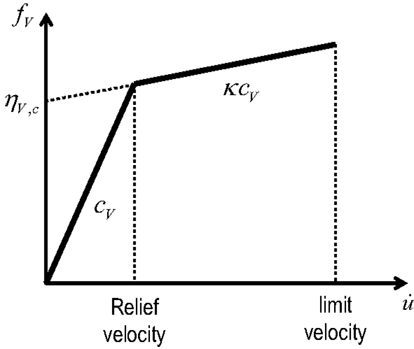
Figure 1. Force–velocity relation of oil damper with relief mechanism.
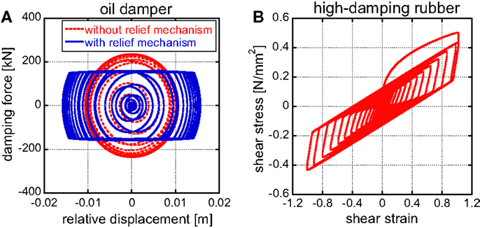
Figure 2. Connecting damper properties: (A) oil damper and (B) high-damping rubber damper.
The high-damping rubber damper (called high-damping rubber later) used in this paper possesses the hybrid characteristics of hysteretic one like metallic dampers and viscoelastic one (Tani et al., 2009). The damper is used as a shear deformation type and the area and thickness of the high-damping rubber damper are the characteristic parameters. An example of the shear stress–shear strain relation is presented in Figure 2B.
Modeling of Connected Building Structures
In the usual connecting damper systems, the fundamental natural frequency of the main structure is smaller than that of the substructure as shown in Figure 3.
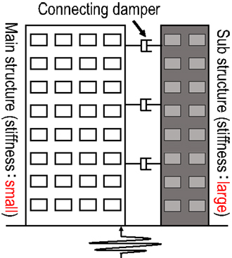
Figure 3. Connecting damper systems in which the fundamental natural frequency of the main structure is smaller than that of the substructure.
Consider first the single-degree-of-freedom (SDOF) model, subjected to the base acceleration , of the main structure (building A) connected with the substructure (building B) using a connecting damper as shown in Figure 4. Let mA, kA, and cA denote the mass, stiffness, and damping coefficient of the main structure and let mB, kB, and cB denote those of the substructure. The damping coefficient of the oil damper is denoted by cD and the area of the high-damping rubber damper is by AD. The thickness of the high-damping rubber damper is to be given. The model parameters of this system are shown in Table 1 and the properties of the dampers are presented in Table 2. The quantities of oil dampers and high-damping rubbers have been determined so that the pre-relief damping ratio in the lowest mode due to the added oil damper is about 0.07 and the response reduction ratio by the high-damping rubber is almost equivalent to that by the oil damper.
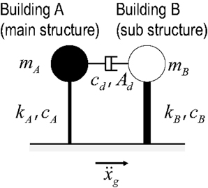
Figure 4. SDOF model, subjected to the base acceleration , of the main structure (building A) connected with the substructure (building B) using a connecting damper.
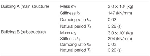
Table 1. Model parameters.
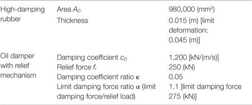
Table 2. Comparison of high-damping rubber and oil damper.
Non-Linear Response of Connected Buildings with Non-Linear Dampers: Harmonic Excitation
Input Base Acceleration
Figure 5 shows the input base acceleration. The input frequency has been determined so that the frequency is resonant to the natural frequency of the main structure (Takewaki, 2006; Takewaki and Tsujimoto, 2011; Murase et al., 2013; Fukumuto and Takewaki, 2015). After a transition process, the input goes into a steady state.
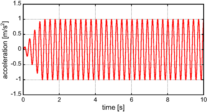
Figure 5. Input base acceleration.
Response Characteristics of Connected Buildings with Different Connecting Dampers and Response Characteristics with Respect to Input Level
Figure 6 shows the relative building displacements without damper and with high-damping rubbers or oil dampers (TB = 0.20 s, oil dampers with relief mechanism). In order to investigate the effect of the separation of building natural periods between buildings A and B, two cases (TB = 0.16, 0.24 s) are added to the model shown in Table 1. However, since the input frequency is resonant to the natural period of building A, the modification of the natural period of building B does not affect so much the relative building displacements. Therefore, the figures for the cases (TB = 0.16, 0.24 s) are not shown here. It can be observed from Figure 6 that while the oil damper reduces the vibration amplitude without the phase change, the high-damping rubber modified the vibration phase slightly. Figure 7 illustrates the horizontal displacement of building A and building B with and without high-damping rubbers. On the other hand, Figure 8 presents the horizontal displacements of building A and building B with and without oil dampers. It can also be seen that while the oil damper reduces the vibration amplitude without the phase change, the high-damping rubber changes the vibration phase. Furthermore, as the separation of building natural periods between buildings A and B becomes large, the effect of dampers on vibration reduction becomes remarkable.
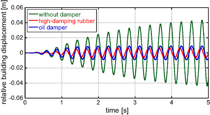
Figure 6. Relative building displacement without damper and with high-damping rubber or oil damper.
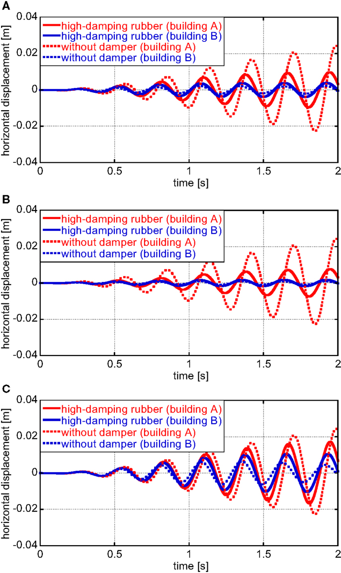
Figure 7. Horizontal displacement of building A and building B with and without high-damping rubbers: (A) TB = 0.2 s, (B) TB = 0.16 s, and (C) TB = 0.24 s.
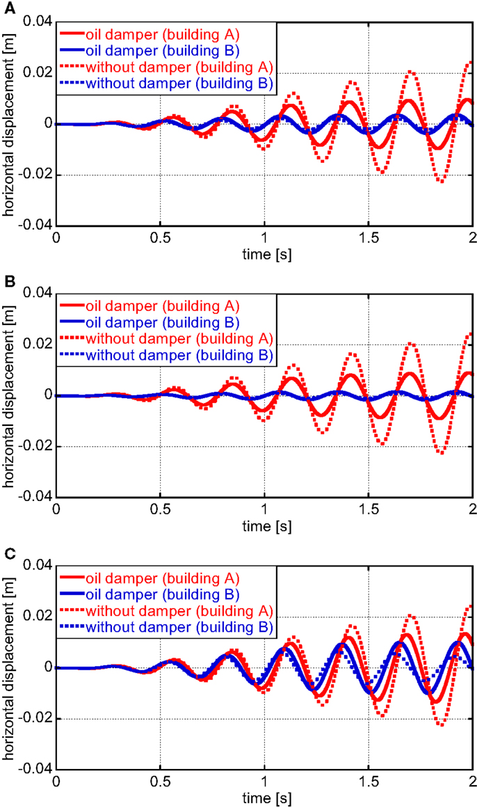
Figure 8. Horizontal displacement of building A and building B with and without oil dampers: (A) TB = 0.2 s, (B) TB = 0.16 s, and (C) TB = 0.24 s.
In order to investigate the effect of building damping ratios on the response, the additional models with the damping ratios hA = hB = 0.03, 0.04, and 0.05 have been treated. Table 3 shows the maximum displacements of buildings A and B. It can be observed that as the structural damping increases, the maximum displacement of building A resonant to the input decreases remarkably. Furthermore, it can also be found that the vibration reduction effect by dampers is retained even for the increased structural damping, although the reduction rate is slightly decreased.
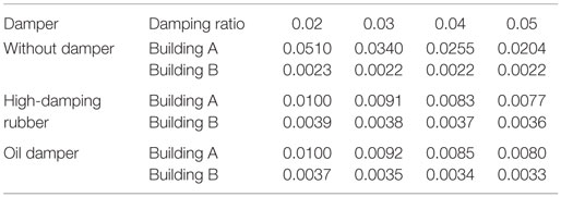
Table 3. Maximum displacements of buildings A and B for various levels of structural damping (meter).
Figure 9 shows the maximum displacement and acceleration of building A with and without dampers with respect to the input acceleration amplitude. The input frequency has been given so as to be resonant to the natural frequency of the main structure. It can be found that while linear oil dampers without relief mechanism can reduce the vibration of the building A effectively for the increasing input level, the performance of the oil dampers with relief mechanism and the high-damping rubber deteriorates for the increasing input level. In particular, while the deterioration rate of the high-damping rubber is gradual, that of the oil dampers with relief mechanism is rapid after a certain limit. Figure 10 presents the maximum relative displacement and damping force with and without dampers with respect to input acceleration amplitude. It can be observed that the high-damping rubber can reduce the relative displacement clearly compared to the oil dampers with relief mechanism.
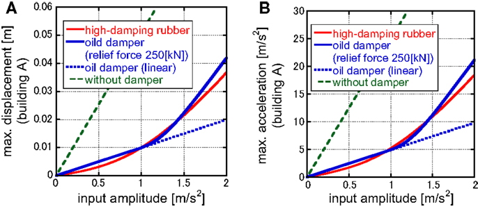
Figure 9. Maximum displacement and acceleration of building A with and without dampers with respect to input acceleration amplitude: (A) maximum displacement and (B) maximum acceleration.
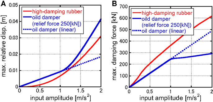
Figure 10. Maximum relative displacement and damping force with and without dampers with respect to input acceleration amplitude: (A) maximum relative displacement and (B) maximum damping force.
The following conclusion may be drawn from Figures 9 and 10. Since the high-damping rubber has stiffness (especially large stiffness in the small deformation range), the resonant phenomenon may be avoided in the small input level. On the other hand, the damping force in the high-damping rubber becomes large.
Non-Linear Response of Connected Buildings with Non-Linear Oil Dampers: Simulated Earthquake Ground Motions
In order to investigate the response characteristics of the connected buildings with the linear and non-linear oil dampers for earthquake ground motions, some numerical examples are shown in this section.
Simulated Earthquake Ground Motions
In this paper, general design ground motions compatible with a specific code-specified design response spectrum in Japan is used. Two representative phase properties are employed to represent the two types of ground motions, i.e., El Centro NS 1940 for the near-field ground motion and Hachinohe NS 1968 for the far-field ground motion. These simulated ground motions have been generated following the method by Gasparini and Vanmarcke (1976). Figure 11 shows the acceleration time history and the acceleration response spectrum with the code-specified design acceleration response spectrum in Japan.
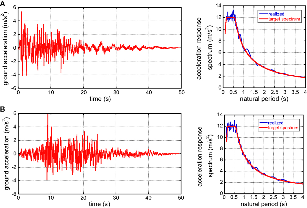
Figure 11. Design earthquake ground motions compatible with the design response spectrum in Japan revised in 2000: (A) phase of El Centro NS 1940 and (B) phase of Hachinohe NS 1968.
Effect of Relief Mechanism of Oil Dampers on Non-Linear Response
In this section, the effect of relief mechanism of oil dampers on non-linear response is investigated. Since it has been reported (Adachi et al., 2013a,b) that if the ratio of the relief load to the maximum damping force in linear case is approximately equal or larger than 0.5, the displacement response of the structure is not affected so much by the relief mechanism. Based on this fact, the relief load shown in Table 4 is used here.
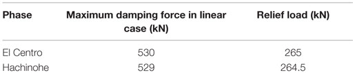
Table 4. Relief load for each input acceleration.
Figure 12A shows the horizontal displacements of building A with and without relief mechanism and energy consumptions by oil dampers (phase: El Centro). On the other hand, Figure 12B illustrates those for the simulated ground motion with the phase of Hachinohe. As pointed out just before, the horizontal displacements of building A is not affected so much by the introduction of relief mechanism. However, it can be seen that the energy dissipation performance of oil dampers with relief mechanism is slightly low compared to the linear oil damper. This performance deterioration occurs early in the El Centro-phase motion and at the intermediate stage in the Hachinohe-phase motion. This timing seems to correspond to the stage at which the large response displacement occurs.
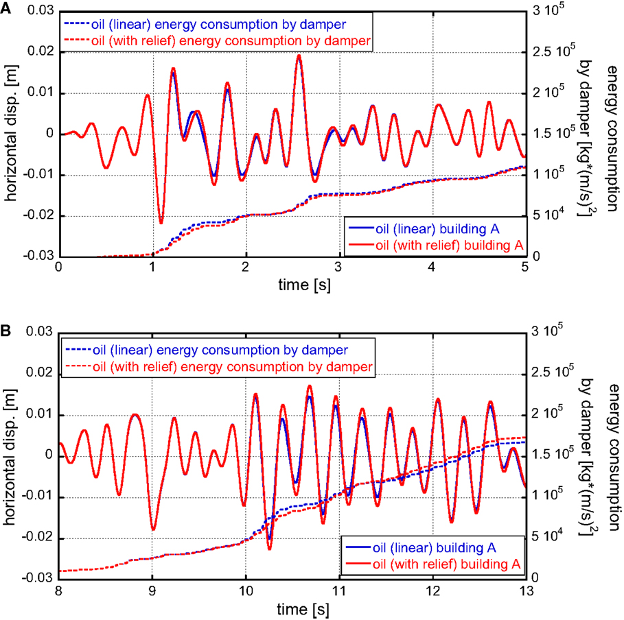
Figure 12. Horizontal displacement and energy consumption by oil dampers: (A) phase: El Centro and (B) phase: Hachinohe.
Table 5 presents the response amplification due to relief mechanism. It can be observed that a remarkable response increase is seen for the simulated ground motion of Hachinohe.
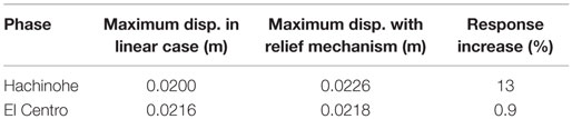
Table 5. Response amplification due to relief mechanism.
Multi-Story Building Model
Consider a three-story connected building system as shown in Figure 13. Although many researches on optimal damper locations have been proposed for linear dampers (for example, Tsuji and Nakamura, 1996; Takewaki, 1997, 2009; Trombetti and Silvestri, 2004; Lavan and Levy, 2006; Aydin et al., 2007; Cimellaro, 2007; Cimellaro and Retamales, 2007), the research on non-linear dampers is very limited (Adachi et al., 2013a). The properties of the main structure and the substructure are shown in Tables 5 and 6. In case of using the same dampers, those are located uniformly at every story.
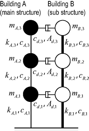
Figure 13. Three-story connected building system.
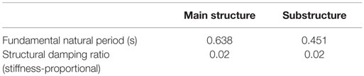
Table 6. Fundamental natural period and damping ratio of main structure and substructure.
Figure 14 shows the input base acceleration. As in the previous case for an SDOF model, the input frequency has been determined so that the frequency is resonant to the fundamental natural frequency of the main structure (Murase et al., 2013). After a transition process, the input goes into a steady state.
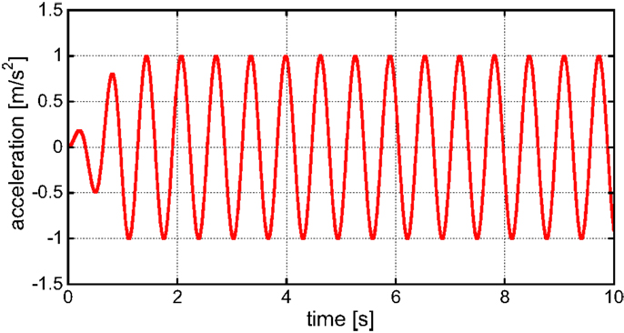
Figure 14. Input base acceleration.
Table 6 presents the fundamental natural period and damping ratio of the main structure and the substructure, and Table 7 shows story mass and stiffness of both structures.
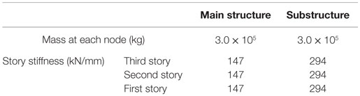
Table 7. Story mass and stiffness.
In the present section, various damper combinations are considered. Table 8 indicates the relationship between the damper combinations and top-mass displacement. The quantities of the dampers are the same as for the SDOF model in the previous section. The oil damper is with the relief mechanism. In this case, the model with the oil dampers in all the stories exhibits the smallest top displacement. However, since this property depends on the input amplitude and other parameters, e.g., the quantity of dampers, a careful attention should be paid. Especially the response velocity in the oil dampers is too large compared to the limit value in low-rise buildings. As for the high-damping rubber dampers, there is no limitation on the response velocity.
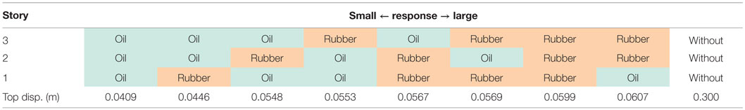
Table 8. Damper location and top-mass displacement.
Figure 15 shows the damping force deformation relation in the first, second, and third stories for the model with oil dampers in all stories and the model with high-damping rubber in the first story and oil dampers in other stories. Table 9 presents the relative building displacement and damping force. It can be observed that the high-damping rubber can reduce the relative building displacement in the first story compared to the model of oil dampers in all stories. Since the high-damping rubber has an issue of damper stroke, it should be used in lower stories.
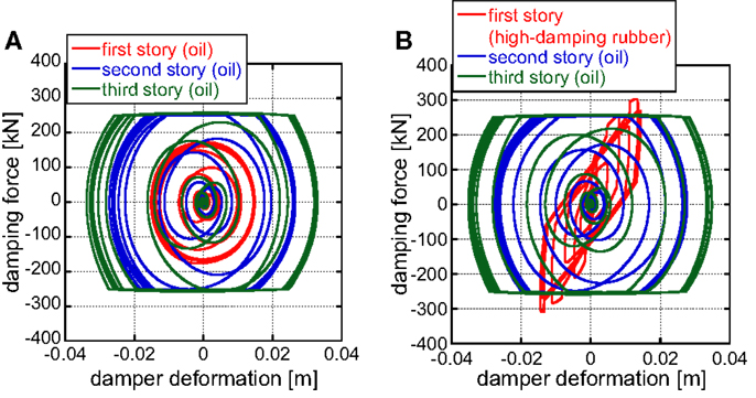
Figure 15. Damping force-deformation relation in the first, second, and third stories: (A) model of oil dampers in all stories and (B) model with high-damping rubber in the first story and oil dampers in other stories.
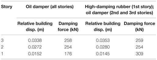
Table 9. Relative building displacement and damping force.
Limit Value of Maximum Velocity of Oil Dampers
It is important to investigate the feasibility of oil dampers. An example of the limit value of the maximum velocity of oil dampers with the limit stroke ±100 (mm) is 150–300 (mm/s).
Table 10 shows the maximum response velocities of the oil dampers computed in Section “Effect of Relief Mechanism of Oil Dampers on Non-Linear Response.” It should be remarked that while the phases of the adopted earthquake ground motions are different, the target acceleration response spectrum is the same. This condition may lead to a similar maximum velocity response of dampers. However, these values are larger than the limit value stated above. It may be concluded that the response velocity in the oil dampers is too large compared to the limit value specifically in low-rise buildings and a special attention should be paid in its use.
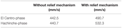
Table 10. Maximum response velocities of oil dampers computed in Section “Effect of Relief Mechanism of Oil Dampers on Non-Linear Response.”
Conclusion
The following conclusions have been derived:
(1) The oil damper and the high-damping rubber damper are both effective dampers for the building connecting system.
(2) While a high-damping rubber damper is effective in a rather small deformation level, an oil damper without relief mechanism is effective in a relatively large deformation level.
(3) While the oil dampers reduce the response in the same phase as the case without dampers, the high-damping rubber dampers change the phase. The merit is that the high-damping rubber can reduce the damper deformation and keep the sufficient space between both buildings. This can mitigate the risk of building pounding.
(4) The oil dampers are effective for the reduction of acceleration. However, the response velocity in the oil dampers is too large compared to the limit value specifically in low-rise buildings as for the high-damping rubber dampers, there is no limitation on the response velocity.
(5) The vibration amplification in the oil damper with relief mechanism should be discussed carefully.
Author Contributions
MK formulated the problem, conducted the computation, and wrote the paper. KF helped the computation. MT discussed the results. IT supervised the research and wrote the paper.
Conflict of Interest Statement
The authors declare that the research was conducted in the absence of any commercial or financial relationships that could be construed as a potential conflict of interest.
Funding
Part of the present work is supported by the Grant-in-Aid for Scientific Research of Japan Society for the Promotion of Science (No. 15H04079) and the joint research with Sumitomo Rubber Industry, Co., in Japan. These supports are greatly appreciated.
References
Adachi, F., Yoshitomi, S., Tsuji, M., and Takewaki, I. (2013a). Nonlinear optimal oil damper design in seismically controlled multi-story building frame. Soil Dyn. Earthq. Eng. 44, 1–13. doi: 10.1016/j.soildyn.2012.08.010
Adachi, F., Fujita, K., Tsuji, M., and Takewaki, I. (2013b). Importance of interstory velocity on optimal along-height allocation of viscous oil dampers in super high-rise buildings. Eng. Struct. 56, 489–500. doi:10.1016/j.engstruct.2013.05.036
Aydin, E., Boduroglub, M. H., and Guney, D. (2007). Optimal damper distribution for seismic rehabilitation of planar building structures. Eng. Struct. 29, 176–185. doi:10.1016/j.engstruct.2006.04.016
Cimellaro, G. P. (2007). Simultaneous stiffness-damping optimization of structures with respect to acceleration, displacement and base shear. Eng. Struct. 29, 2853–2870. doi:10.1016/j.engstruct.2007.01.001
Cimellaro, G. P., and Lopez-Garcia, D. (2011). Algorithm for design of controlled motion of adjacent structures. Struct. Control Health Monit. 18, 140–148. doi:10.1002/stc.357
Cimellaro, G. P., and Retamales, R. (2007). Optimal softening and damping design for buildings. Struct. Control Health Monit. 14, 831–857. doi:10.1002/stc.181
Fukumuto, Y., and Takewaki, I. (2015). Critical demand of earthquake input energy to connected building structures. Earthq. Struct. 9, 1133–1152.
Gasparini, D. A., and Vanmarcke, E. H. (1976). Simulated Earthquake Motions Compatible with Prescribed Response Spectra – SIMQKE, A Computer Program Distributed by NISEE/Computer Applications. Berkeley, CA.
Hanson, R. D., and Soong, T. T. (2001). Seismic Design with Supplemental Energy Dissipation Devices. Oakland, CA: EERI.
Iwanami, K., Suzuki, K., and Seto, K. (1996). Vibration control method for parallel structures connected by damper and spring. JSME Int. J. 39, 714–720.
Lavan, O., and Levy, R. (2006). Optimal design of supplemental viscous dampers for linear framed structures. Earthq. Eng. Struct. Dyn. 35, 337–356. doi:10.1002/eqe.524
Luco, J. E., and de Barros, F. C. P. (1998). Control of seismic response of a composite tall building modeled by two interconnected shear beams. Earthq. Eng. Struct. Dyn. 17, 205–242. doi:10.1002/(SICI)1096-9845(199803)27:3<205::AID-EQE712>3.0.CO;2-X
Murase, M., Tsuji, M., and Takewaki, I. (2013). Smart passive control of buildings with higher redundancy and robustness using base-isolation and inter-connection. Earthq. Struct. 4, 649–670. doi:10.12989/eas.2013.4.6.649
Patel, C. C., and Jangid, R. S. (2011). Dynamic response of adjacent structures connected by friction dampers. Earthq. Struct. 2, 149–169. doi:10.12989/eas.2011.2.2.149
Richardson, A., Walsh, K. K., and Abdullah, M. M. (2013a). Closed-form design equations for controlling vibrations in connected structures. J. Earthq. Eng. 17, 699–719. doi:10.1080/13632469.2013.771590
Richardson, A., Walsh, K. K., and Abdullah, M. M. (2013b). Closed-form design equations for coupling linear structures using stiffness and damping elements. Struct. Control Health Monit. 20, 259–281. doi:10.1002/stc.490
Soong, T. T., and Dargush, G. F. (1997). Passive Energy Dissipation Systems in Structural Engineering. Chichester: John Wiley & Sons.
Takewaki, I. (1997). Optimal damper placement for minimum transfer functions. Earthq. Eng. Struct. Dyn. 26, 1113–1124. doi:10.1002/(SICI)1096-9845(199711)26:11<1113::AID-EQE696>3.0.CO;2-X
Takewaki, I. (2006). Critical Excitation Methods in Earthquake Engineering. Amsterdam: Elsevier Science.
Takewaki, I. (2007). Earthquake input energy to two buildings connected by viscous dampers. J. Struct. Eng. 133, 620–628. doi:10.1061/(ASCE)0733-9445(2007)133:5(620)
Takewaki, I. (2009). Building Control with Passive Dampers: Performance-Based Design for Earthquakes. John Wiley & Sons.
Takewaki, I. (2015). “Fundamental properties of earthquake input energy on single and connected building structures, Chapter 1,” in New Trends in Seismic Design of Structures, eds. Lagaros N. D., Tsompanakis Y., and Papadrakakis M. (Stirlingshire: Saxe-Coburg Publisher), 1–28.
Takewaki, I., and Tsujimoto, H. (2011). Scaling of design earthquake ground motions for tall buildings based on drift and input energy demands. Earthq. Struct. 2, 171–187. doi:10.12989/eas.2011.2.2.171
Tani, T., Yoshitomi, S., Tsuji, M., and Takewaki, I. (2009). High-performance control of wind-induced vibration of high-rise building via innovative high-hardness rubber damper. J. Struct. Des. Tall Spec. Build. 18, 705–728. doi:10.1002/tal.457
Trombetti, T., and Silvestri, S. (2004). Added viscous dampers in shear-type structures: the effectiveness of mass proportional damping. J. Earthq. Eng. 8, 275–313. doi:10.1080/13632460409350490
Keywords: building connection, passive damper, non-linearity, structural control, high-damping rubber damper, oil damper, relief mechanism, smart structure
Citation: Kasagi M, Fujita K, Tsuji M and Takewaki I (2016) Effect of Non-linearity of Connecting Dampers on Vibration Control of Connected Building Structures. Front. Built Environ. 1:25. doi: 10.3389/fbuil.2015.00025
Received: 20 November 2015; Accepted: 14 December 2015;
Published: 11 January 2016
Edited by:
Nikos D. Lagaros, National Technical University of Athens, GreeceReviewed by:
Ehsan Noroozinejad Farsangi, Kerman Graduate University of Advanced Technology, IranAli Koçak, Yildiz Technical University, Turkey
Copyright: © 2016 Kasagi, Fujita, Tsuji and Takewaki. This is an open-access article distributed under the terms of the Creative Commons Attribution License (CC BY). The use, distribution or reproduction in other forums is permitted, provided the original author(s) or licensor are credited and that the original publication in this journal is cited, in accordance with accepted academic practice. No use, distribution or reproduction is permitted which does not comply with these terms.
*Correspondence: Izuru Takewaki, takewaki@archi.kyoto-u.ac.jp