Closed-Form Overturning Limit of Rigid Block under Critical Near-Fault Ground Motions
 Kunihiko Nabeshima
 Ryo Taniguchi
 Kotaro Kojima
 Izuru Takewaki
- Department of Architecture and Architectural Engineering, Graduate School of Engineering, Kyoto University, Kyoto, Japan
A closed-form limit on the input level of the double impulse as a substitute of a near-fault ground motion is derived for the overturning of a rigid block. The rocking vibration of the rigid block is formulated by using the conservation law of angular momentum and the conservation law of mechanical energy. The initial rotational velocity after the first impulse and the rotational velocity after the impact are determined by the conservation law of angular momentum. The velocity change after the second impulse is also characterized by the conservation law of angular momentum. The maximum angles of rotation of the rigid block in both the clockwise and anti-clockwise directions, which are needed for the computation of the overturning limit, are derived by the conservation law of mechanical energy. This enables us to avoid the computation of complicated non-linear time-history responses. The critical timing of the second impulse to the first impulse is characterized by the time of impact after the first impulse. It is clarified that the action of the second impulse just after the impact corresponds to the critical timing. It is derived from the closed-form expression of the critical velocity amplitude limit of the double impulse that its limit is proportional to the square root of size, i.e., the scale effect.
Introduction
The rocking response of rigid blocks is important in the evaluation of earthquake response of monuments, slender buildings, and furniture (or box on rack stores). In the seismic risk analysis of base-isolated high-rise buildings in Japan, this investigation is critical because most isolators do not have tensile resistance and overturning of such buildings should be prohibited at all. Historically, in the earthquake structural engineering, the overturning rate of tombstones during an earthquake has often been used in estimating the peak ground accelerations and velocities.
The research on rocking response of rigid blocks under earthquake ground motions has been investigated extensively since the pioneering work by Milne (1885) and Housner (1963). Yim et al. (1980) conducted extensive investigation for many recorded ground motions based on the work by Housner (1963). Ishiyama (1982) studied various types of non-linearity of the overturning response of a rigid block in detail. After these works, many investigations have been conducted so far (Priestley et al., 1978; Spanos and Koh, 1984; Hogan, 1989, 1990; Shenton and Jones, 1991; Pompei et al., 1998; Andreaus and Casini, 1999; Anooshehpoor et al., 1999; Zhang and Makris, 2001; Prieto et al., 2004; Yilmaz et al., 2009; ElGawady et al., 2010; DeJong, 2012; Dimitrakopoulos and DeJong, 2012a,b). Recently, DeJong (2012) and Dimitrakopoulos and DeJong (2012a,b) investigated the rocking motion and overturning of a rigid block in detail and derived important results. Furthermore, Makris and Kampas (2016) investigated the scale effect of blocks on the overturning limit level of sinusoidal inputs and earthquake ground motions.
It appears that active discussions on the property of near-fault ground motions started since Parkfield earthquake in 1966 and San Fernando earthquake in 1971. The peculiar influences of near-fault ground motions on structural response have been investigated extensively and in detail (Bertero et al., 1978; Hall et al., 1995; Sasani and Bertero, 2000; Alavi and Krawinkler, 2004; Makris and Black, 2004; Mavroeidis et al., 2004; Kalkan and Kunnath, 2006; Xu et al., 2007; Rupakhety and Sigbjörnsson, 2011; Yamamoto et al., 2011; Minami and Hayashi, 2013; Khaloo et al., 2015; Vafaei and Eskandari, 2015). These investigations paid attention to the principal part of such ground motions and clarified the essential features of near-fault ground motions. Then, such investigations made clear the existence of the fling-step and forward-directivity inputs (Mavroeidis and Papageorgiou, 2003; Bray and Rodriguez-Marek, 2004; Kalkan and Kunnath, 2006; Mukhopadhyay and Gupta, 2013a,b; Zhai et al., 2013; Hayden et al., 2014; Yang and Zhou, 2014). In particular, Northridge earthquake in 1994, Hyogoken-Nanbu earthquake in 1995, and Chi-Chi earthquake in 1999 alerted many earthquake structural engineers and designers for the need of consideration of such effects in the structural design of buildings and infrastructures.
It is noteworthy that the principal parts of the fling-step and forward-directivity inputs can be substituted by a few wavelets or a series of harmonic waves. Actually, many useful attempts have been made. As a milestone in this field, Mavroeidis and Papageorgiou (2003) summarized the characteristics of this class of ground motions and proposed some simple models.
It is also important to note the history of non-linear response analysis of structures. In an early stage of structural dynamics, the resources of computers are quite limited and the elastic–plastic earthquake responses were investigated primarily for the steady-state response to harmonic input or the transient response to an extremely simple sinusoidal input in 1960–1970s (Caughey, 1960a,b; Iwan, 1961, 1965a,b). After development of methods for sophisticated mathematical description of those responses, such simple techniques have been applied to more complex problems. On the other hand, although applicable only for simplified inputs, Kojima and Takewaki (2015a,b,c, 2016a,b) proposed recently a completely different approach using a double impulse and demonstrated that the peak elastic–plastic response can be derived by using an energy approach without solving directly the equations of motion even for models with negative post-yield stiffness.
In the earthquake-resistant design, the resonance plays a key role (Drenick, 1970; Takewaki, 2007; Moustafa et al., 2010; Takewaki et al., 2012), and it has a strong effect even in case of near-fault ground motions with short duration. While the resonant equivalent frequency had to be computed for a specified input level by changing the excitation frequency in a parametric manner in the conventional methods (Caughey, 1960a,b; Iwan, 1961, 1965a,b), no iteration is required in the recently proposed method for the double impulse (Kojima and Takewaki, 2015a). They demonstrated that the resonance can be proved by using energetic investigation and the critical timing of the second impulse can be characterized as the time with zero restoring force. This advantageous feature is retained also in this paper for the structures with negative second slope, although the present model has a non-linear elastic restoring-force characteristic. They also made clear that the maximum elastic–plastic response after impulse can be obtained by equating the initial kinetic energy computed by the initial velocity to the sum of hysteretic and elastic strain energies. It should be reminded that while most of the previous researches on near-fault ground motions are aimed at disclosing the response characteristics of elastic or elastic–plastic structures with arbitrary stiffness and strength parameters and require tremendous amount of numerical task, the present paper focused on the critical response (resonant response) and enabled the drastic reduction of computational works. Once the critical case is made clear, it is expected that the other non-resonant case provides a more stable situation.
In the present paper, not only a closed-form expression of the critical velocity amplitude limit of the double impulse for overturning of a rigid block is obtained but also the scale effect in the overturning limit is made clear. It is concluded from such closed-form expression that its limit is proportional to the square root of size.
Double Impulse Input
In this paper, it is intended to model a principal part of a near-fault ground motion into a one-cycle sinusoidal wave (Kalkan and Kunnath, 2006) and then simplify such one-cycle sinusoidal wave into a double impulse following Kojima and Takewaki (2015a,c, 2016a,b), Kojima et al. (2015), and Taniguchi et al. (2016), as shown in Figure 1. This is because the double impulse in the form of shock has a simple characteristic and a straightforward expression of the response can be expected even for non-linear elastic responses based on an energy approach to free vibrations.
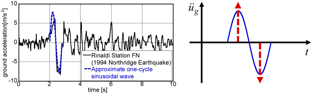
Figure 1. Modeling of principal part of near-fault ground motion into one-cycle sinusoidal wave and modeling of such one-cycle sinusoidal wave into double impulse.
Following Kojima and Takewaki (2015a), consider a ground acceleration as double impulse, as shown in Figure 1, expressed by
where V is the given initial velocity (also the second velocity with an opposite sign) and t0 is the time interval between two impulses. The time derivative is denoted by an over-dot. The comparison with the corresponding one-cycle sinusoidal wave is plotted in Figure 1. The corresponding velocity and displacement of such double impulse and sinusoidal wave can also be found in Kojima and Takewaki (2015a). It has been confirmed that the double impulse is a good approximation of the corresponding sinusoidal wave even in the form of velocity and displacement. However, the correspondence in the response should be discussed carefully.
The Fourier transform of the acceleration of the double impulse can be derived as
As a comparative approach, an equivalent linearization method exists. While most of the previous methods (Caughey, 1960a,b; Iwan, 1961) employ the equivalent linearization of the structural model for the unchanged input (see Figure 2A including an equivalent linear stiffness), the method proposed in the works (Kojima and Takewaki, 2015a) and in this paper transforms the input into the double impulse for the unchanged structural model (see Figure 2B). It should be noted that the negative second slope cannot be dealt with by the equivalent linearization.
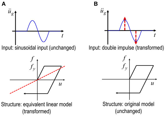
Figure 2. Feature of method of input transformation against method of structural model transformation: (A) previous method (equivalent linearization of structural model for unchanged input) and (B) new method (transformation of input into double impulse for unchanged structural model).
Maximum Rotation of Rigid Block Subjected to Critical Double Impulse
Consider the rocking response of a rigid block of mass m with width 2b and height 2h under a base horizontal acceleration input as shown in Figure 3 (input of does not cause any problem). The geometrical properties can be expressed by the length and angle α as shown in Figure 3. Let I [=(4/3)mR2] and g denote the mass moment of inertia around the edge of bottom right (also bottom left) and the acceleration of gravity, respectively. It is well known that this model can be substituted by a rigid bar, as shown in Figure 3, with the same mass moment of inertia supported by a non-linear elastic rotational spring with rigid initial stiffness and negative second slope. The moment-rotation relation of the non-linear elastic rotational spring with rigid initial stiffness and negative second slope is shown in Figure 4.
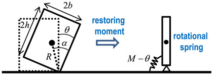
Figure 3. Modeling of rocking rigid block by rigid bar supported by non-linear elastic rotational spring with rigid initial stiffness and negative second slope.
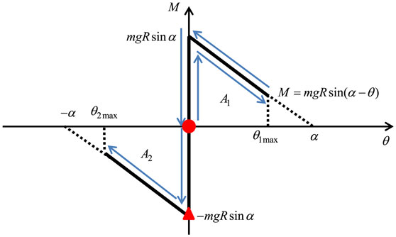
Figure 4. Moment-rotation relation for rocking response of rigid block and timing of double impulse.
It is assumed here that slipping of the block is ignored for simplicity. In addition, a scenario that the overturning occurs after the second impulse is employed in this paper. This scenario seems valid because the input limit on the overturning corresponding to this scenario provides a lower limit in general. As for more detailed scenarios, see Ishiyama (1982) and Dimitrakopoulos and DeJong (2012b).
The critical timing of the second impulse is at the impact where the rotational velocity attains the maximum [see Kojima and Takewaki (2015a)]. Furthermore, it can be shown that critical timing is just after the impact because the rotational velocity is reduced greatly at the impact. More detailed verification of the critical timing of the second impulse is shown in Appendix.
Let θ(t) denote the angle of rotation of the rigid block (clockwise direction is positive). The equation of motion for this rigid block can be expressed by
The maximum angle of rotation after the first impulse is expressed by θ1max and that after the second impulse is described by θ2max.
The first conservation law of angular momentum [conservation of angular momentum (1) in Figure 5] can be given by
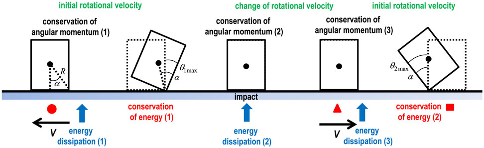
Figure 5. Rocking response of rigid block and governing law (conservation of angular momentum, conservation of energy, and energy dissipation).
From Eq. 4, the initial rotational velocity after the first impulse can be obtained as
The first conservation law of mechanical energy [conservation of energy (1) in Figure 5] after substitution of Eq. 5 yields
A1 is the area of near trapezoid corresponding to θ1max shown in Figure 4. From Eq. 6, once the velocity amplitude V of the double impulse is given, θ1max can be obtained.
The second conservation law of angular momentum [conservation of angular momentum (2) in Figure 5] at the impact (: rotational velocity just before the impact) can be given by
This conservation law is applied at the pivot point. Since the rotation occurs around the bottom right before the impact, two terms appear in the left side of Eq. 7. Following Housner (1963), the rotational velocity just after the impact may be expressed by
where r can be obtained from Eq. 7 as
This parameter r was introduced by Housner (1963). When the boundary condition between the block and the base is necessary to consider, e.g., the surface material properties (ElGawady et al., 2010) or the rocking of tall buildings (limited contact area), another coefficient should be added on the parameter r.
Using the conservation law of angular momentum [conservation of angular momentum (3) in Figure 5] just after the second impulse, the rotational velocity change by the second impulse can be expressed by
In this case, the rotational velocity just after the second impulse can be obtained as
The rotation angle is obtained based on the Housner’s formulation (conservation law of angular momentum at the impact), and is derived from the transformation of the horizontal impulse into rotation [the same treatment is made in Eq. 4]. Since these two phenomena occur in time sequence, summation of the angles of rotation can be verified.
The second conservation law of mechanical energy [conservation of energy (2) in Figure 5] can then be expressed by
A2 is the area of near trapezoid corresponding to θ2max shown in Figure 4.
It may be interesting to note the quantity of energy dissipation during the rocking response. The energy dissipation [energy dissipation (1) in Figure 5] can be understood by
The energy dissipation [energy dissipation (2) in Figure 5] can be expressed by
The critical timing t0 can be obtained approximately [for linear approximation: see Housner (1963)] by solving the equation of free-rocking motion from the first impulse to the second impulse.
where p2 = mgR/I. It should be noted that θ1max has been obtained in Eq. 6.
Limit Input Level of Critical Double Impulse Characterizing Overturning of Rigid Block
The overturning of the rigid block can be characterized by the coincidence of θ2max with −α as shown in Figure 6.
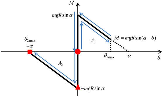
Figure 6. Moment-rotation relation for rocking response of rigid block and limit of overturning.
In this case, the near trapezoid corresponding to the area A2 in Figure 4 is reduced to the near triangle. Eq. 12 can then be expressed as follows:
By substituting Eqs 8 and 10 into Eq. 11 and then the resulting expression into Eq. 17, Eq. 17 can be reduced to
The critical velocity amplitude of the double impulse can then be obtained as follows:
It can be observed that the critical velocity amplitude of the double impulse is proportional to the square root of size. This finding is an important instruction for structural design of monuments and tall buildings, i.e., as the structure becomes larger, it becomes more stable.
The critical timing t0 can be computed as the time between the first impulse and the second impulse. This quantity can be obtained by solving the linearized equation of motion in the positive rotation range. When the critical condition is substituted and linearization is introduced in the evaluation of θ1max, Eq. 15 is reduced to the following form.
The flowchart for finding the critical velocity amplitude of the double impulse is shown in Figure 7.
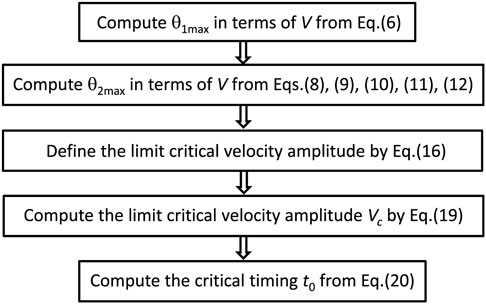
Figure 7. Flowchart for finding critical velocity amplitude of double impulse.
When we deal with the equivalent one-cycle sinusoidal wave (period Tp = 2t0), it can be shown that the velocity amplitude Vp of the equivalent one-cycle sinusoidal wave [the maximum Fourier amplitude is equivalent (Kojima and Takewaki, 2015a)] is proportional to V of the double impulse (Vp/V = 1.22218898 …). In this case, the acceleration amplitude Ap can be obtained from Ap = ωpVp/2, where ωp = 2π/Tp.
Numerical Examples and Discussion
In order to demonstrate the accuracy and reliability of the proposed method, numerical examples are introduced. Consider three numerical examples of rectangular columns with width 2b = 1, 2, and 4 m corresponding to Makris and Kampas (2016). The column height is changed parametrically.
Figure 8 shows the plot of the limit velocity amplitude Vc of the critical double impulse with respect to R for the abovementioned three models computed by Eq. 19. The limit of velocity amplitude by the numerical simulation of time-history response is also plotted in Figure 8. This numerical simulation limit has been obtained by changing the velocity amplitude to the overturning together with the corresponding critical impulse timing, which has been derived by the present formulation, i.e., Eq. 20. The numerical integration has been conducted by the fourth-order Runge–Kutta method (the time increment = 0.001 s). It can be understood that the proposed closed-form limit velocity amplitude of the critical double impulse coincides fairly well with the numerical simulation result and is quite reliable.
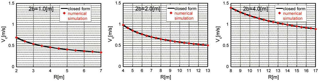
Figure 8. Limit velocity amplitude of critical double impulse with respect to R for 2b = 1, 2, and 4 m (closed-form expression and numerical simulation).
Figure 9 presents the critical timing given by Eq. 20 with respect to R for the abovementioned three models together with the plot by the numerical simulation for the non-linear model. In the numerical simulation, the equation of free-rocking motion has been solved numerically (numerically integrated), and the time interval between the first impulse and the second impulse has been employed as the critical timing. It should be remarked that the closed-form critical timing is based on linear approximation of the equation of motion as in Housner (1963), and a slight difference with the result by the numerical simulation for the non-linear case can be seen in the range of smaller height. However, it appears that this difference is negligible.
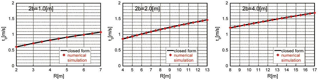
Figure 9. Critical timing with respect to R for 2b = 1, 2, and 4 m (closed-form expression for linearized model and numerical simulation for non-linear model).
Figure 10 illustrates the limit acceleration amplitude divided by the acceleration of gravity of the equivalent one-cycle sinusoidal input. The amplitude is evaluated by the transformation mentioned above, i.e., Ap = ωpVp/2, Vp/Vc = 1.22218898 …, ωp = 2π/Tp, and Tp = 2t0. In addition, Figure 10 shows the magnified plot with the factor 1.53. This factor has been introduced from the viewpoint of the equivalence of response between the double impulse (also one-cycle maximum-Fourier-amplitude equivalent sinusoidal wave) and the one-cycle rocking-response-equivalent sinusoidal wave. This magnification will be discussed in Figure 11. Other data from Makris and Kampas (2016) and Dimitrakopoulos and DeJong (2012b) (coefficient of restitution = 0.8) and the West’s formula (Milne, 1885) have also been plotted for comparison. The plots from Makris and Kampas (2016) and Dimitrakopoulos and DeJong (2012b) are limited because only the resonant one is picked up. It can be observed that the proposed magnified expression correspond fairly well to other results for resonance.
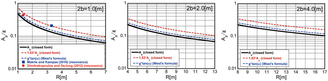
Figure 10. Critical acceleration amplitude ratio of equivalent one-cycle sinusoidal input to acceleration of gravity for 2b = 1, 2, and 4 m and comparison with other results.
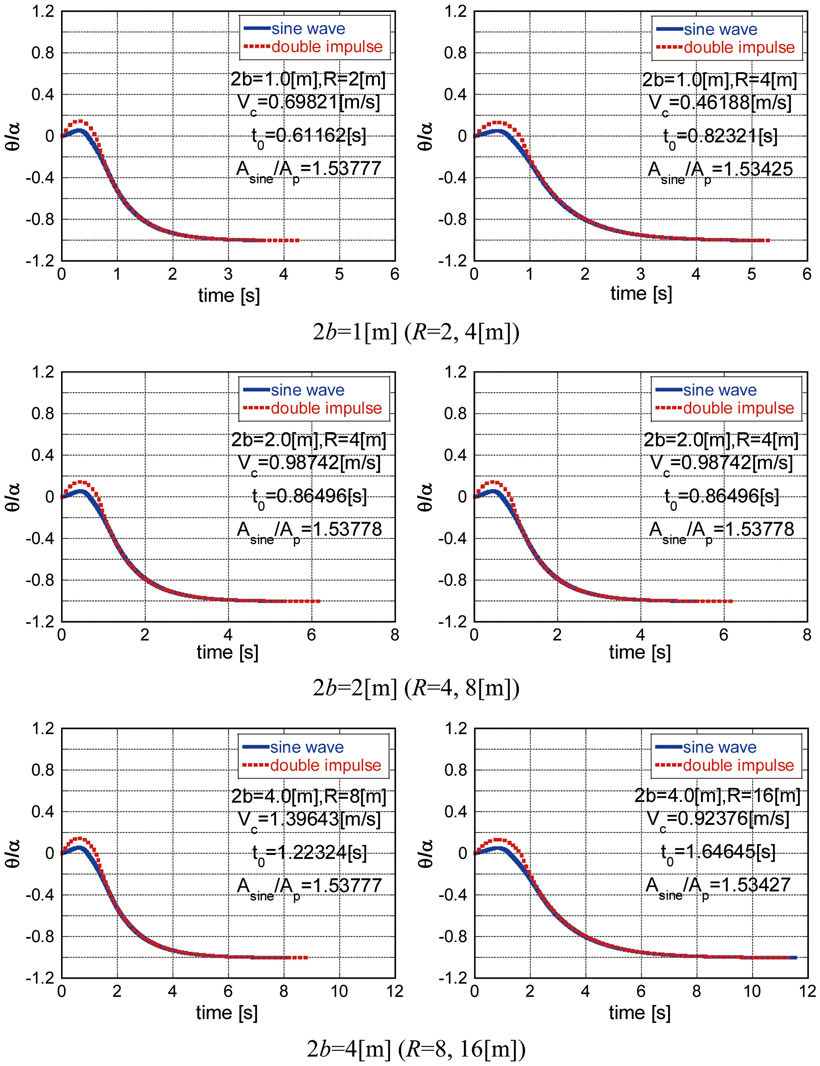
Figure 11. Comparison of time-history responses θ(t)/α at overturning limit between the double impulse, and the corresponding equivalent one-cycle sinusoidal wave magnified by a coefficient about 1.53–1.54.
Figure 11 shows several comparisons (2b = 1, 2, and 4 m) of time-history responses θ(t)/α at the overturning limit between the double impulse and the corresponding equivalent one-cycle sinusoidal wave magnified by a certain coefficient (Asine: amplitude of magnified sine wave). It has been found that when the amplitude of the equivalent one-cycle sinusoidal wave is magnified by a coefficient about 1.53–1.54, both response amplitudes coincide fairly well. This phenomenon may come from the fact that while the resonance is guaranteed for the double impulse, that is not for the equivalent one-cycle sinusoidal wave. The difference of just before the impact may be another cause.
The introduction of two-step transformation of the magnitude of the equivalent sinusoidal waves (introduction of the one-cycle sinusoidal wave equivalent to the double impulse in Section “Limit Input Level of Critical Double Impulse Characterizing Overturning of Rigid Block” and magnification of the equivalent one-cycle sinusoidal wave in this section) is due to the viewpoint of the equivalence of the maximum Fourier amplitude and from the viewpoint of connection to the previous related works by the present authors. If the readers prefer the correction factor, they can multiply Vp/V = 1.22218898 … and Asine/Ap = 1.53–1.54.
Conclusion
A closed-form limit on the input level of the double impulse as a representative of the principal part of a near-fault ground motion has been derived for the overturning of a rigid block. The conclusions may be summarized as follows:
(1) The rocking vibration of a rigid block has been formulated by using the conservation law of angular momentum and the conservation law of mechanical energy. On the one hand, the conservation law of angular momentum has been used in determining the initial rotational velocity just after the first impulse and the rotational velocity change at the impact and the second impulse. On the other hand, the conservation law of energy has been used in obtaining the maximum rotational angle after the first impulse and that after the second impulse, which are needed for the computation of the overturning limit. This enabled us to avoid the computation of complicated non-linear time-history responses.
(2) The critical timing of the second impulse has been characterized by the time of impact after the first impulse. It has been clarified that the action of the second impulse just after the impact corresponds to the critical timing.
(3) The overturning of the rigid block can be characterized by the coincidence of the maximum rotational angle θ2max after the second impulse with the limit value −α of rotation. This condition gives the critical velocity amplitude of the double impulse just inducing the overturning of the rigid block. Since the area A2 in the restoring-force characteristic in the negative side can be obtained in closed form in terms of the velocity amplitude of the double impulse by using the conservation law of energy (Eq. 12) in which the initial velocity of rotational angle has been derived in closed form in Eq. 11, the critical velocity amplitude limit of the double impulse can be obtained.
(4) It has been found from the closed-form expression of the critical velocity amplitude limit of the double impulse that it is proportional to the square root of size of the rigid block. This finding is an important instruction for structural design of monuments and tall buildings, i.e., as the structure becomes larger, it becomes more stable.
(5) Numerical examples, including the comparison with the numerical simulation results by the Runge–Kutta method, demonstrated the accuracy and reliability of the proposed method. However, as for the comparison of the response to the double impulse with that to the equivalent sinusoidal wave, a magnification coefficient (about 1.53–1.54 in this case) should be introduced for guaranteeing the correspondence of the responses to the double impulse and to the equivalent one-cycle sinusoidal wave. The introduction of two-step transformation of the magnitude of the equivalent sinusoidal waves (introduction of the one-cycle sinusoidal wave equivalent to the double impulse and magnification of the equivalent one-cycle sinusoidal wave) is due to the viewpoint of the equivalence of the maximum Fourier amplitude and from the viewpoint of connection to the previously related works by the present authors.
(6) The proposed magnified overturning limit exhibits a fairly good correspondence to the other available data for resonance (Makris and Kampas, 2016; Dimitrakopoulos and DeJong, 2012b).
Although only the critical input was dealt with in this paper, it gives the lowest level of the limit input. If the input timing is not critical, it gives smaller responses.
Author Contributions
KN formulated the problem and theory. RT carried out the theoretical and numerical analysis. KK helped the numerical analysis. IT supervised the theoretical analysis and organized the research group. All authors read and approved the final manuscript.
Conflict of Interest Statement
The authors declare that the research was conducted in the absence of any commercial or financial relationships that could be construed as a potential conflict of interest.
Funding
Part of the present work is supported by the Grant-in-Aid for Scientific Research (KAKENHI) of Japan Society for the Promotion of Science (No. 15H04079). This support is greatly appreciated.
References
Alavi, B., and Krawinkler, H. (2004). Behaviour of moment resisting frame structures subjected to near-fault ground motions. Earthq. Eng. Struct. Dyn. 33, 687–706. doi: 10.1002/eqe.369
Andreaus, U., and Casini, P. (1999). On the rocking-uplifting motion of a rigid block in free and forced motion: influence of sliding and impact. Acta Mech. 138, 219–241. doi:10.1007/BF01291846
Anooshehpoor, A., Heaton, T. H., Shi, B., and Brune, J. N. (1999). Estimates of the ground accelerations at point Reyes station during the 1906 San Francisco earthquake. Bull. Seismol. Soc. Am. 89, 845–853.
Bertero, V. V., Mahin, S. A., and Herrera, R. A. (1978). Aseismic design implications of near-fault San Fernando earthquake records. Earthq. Eng. Struct. Dyn. 6, 31–42. doi:10.1002/eqe.4290060105
Bray, J. D., and Rodriguez-Marek, A. (2004). Characterization of forward-directivity ground motions in the near-fault region. Soil Dyn. Earthq. Eng. 24, 815–828. doi:10.1016/j.soildyn.2004.05.001
Caughey, T. K. (1960a). Sinusoidal excitation of a system with bilinear hysteresis. J. Appl. Mech. 27, 640–643. doi:10.1115/1.3644077
Caughey, T. K. (1960b). Random excitation of a system with bilinear hysteresis. J. Appl. Mech. 27, 649–652. doi:10.1115/1.3644077
DeJong, M. J. (2012). Amplification of rocking due to horizontal ground motion. Earthq. Spectra 28, 1405–1421. doi:10.1193/1.4000085
Dimitrakopoulos, E. G., and DeJong, M. J. (2012a). Overturning of retrofitted rocking structures under pulse-type excitation. J. Eng. Mech. 138, 963–972. doi:10.1061/(ASCE)EM.1943-7889.0000410
Dimitrakopoulos, E. G., and DeJong, M. J. (2012b). Revisiting the rocking block: closed-form solutions and similarity laws. Proc. R. Soc. A 468, 2294–2318. doi:10.1098/rspa.2012.0026
ElGawady, M. A., Ma, Q., Butterworth, J. W., and Ingham, J. (2010). Effects of interface material on the performance of free rocking blocks. Earthq. Eng. Struct. Dyn. 40, 375–392. doi:10.1002/eqe.1025
Hall, J. F., Heaton, T. H., Halling, M. W., and Wald, D. J. (1995). Near-source ground motion and its effects on flexible buildings. Earthq. Spectra 11, 569–605. doi:10.1193/1.1585828
Hayden, C. P., Bray, J. D., and Abrahamson, N. A. (2014). Selection of near-fault pulse motions. J. Geotech. Geoenviron. Eng. 140, 04014030. doi:10.1061/(ASCE)GT.1943-5606.0001129
Hogan, S. J. (1989). On the dynamics of rigid-block motion under harmonic forcing. Proc. R. Soc. Lond. A 425, 441–476. doi:10.1098/rspa.1989.0114
Hogan, S. J. (1990). The many steady state responses of a rigid block under harmonic forcing. Earthq. Eng. Struct. Dyn. 19, 1057–1071. doi:10.1002/eqe.4290190709
Housner, G. W. (1963). The behavior of inverted pendulum structures during earthquakes. Bull. Seismol. Soc. Am. 53, 404–417.
Ishiyama, Y. (1982). Motions of rigid bodies and criteria for overturning by earthquake excitations. Earthq. Eng. Struct. Dyn. 10, 635–650. doi:10.1002/eqe.4290100502
Iwan, W. D. (1961). The Dynamic Response of Bilinear Hysteretic Systems. Ph.D. thesis, California Institute of Technology, Pasadena.
Iwan, W. D. (1965a). “The dynamic response of the one-degree-of-freedom bilinear hysteretic system,” in Proc. of the Third World Conf. on Earthquake Eng (New Zealand).
Iwan, W. D. (1965b). The steady-state response of a two-degree-of-freedom bilinear hysteretic system. J. Appl. Mech. 32, 151–156. doi:10.1115/1.3625711
Kalkan, E., and Kunnath, S. K. (2006). Effects of fling step and forward directivity on seismic response of buildings. Earthq. Spectra 22, 367–390. doi:10.1193/1.2192560
Khaloo, A. R., Khosravi, H., and Hamidi Jamnani, H. (2015). Nonlinear interstory drift contours for idealized forward directivity pulses using “modified fish-bone” models. Adv. Struct. Eng. 18, 603–627. doi:10.1260/1369-4332.18.5.603
Kojima, K., Fujita, K., and Takewaki, I. (2015). Critical double impulse input and bound of earthquake input energy to building structure. Front. Built Environ. 1:5. doi:10.3389/fbuil.2015.00005
Kojima, K., and Takewaki, I. (2015a). Critical earthquake response of elastic-plastic structures under near-fault ground motions (part 1: fling-step input). Front. Built Environ. 1:12. doi:10.3389/fbuil.2015.00012
Kojima, K., and Takewaki, I. (2015b). Critical earthquake response of elastic-plastic structures under near-fault ground motions (part 2: forward-directivity input). Front. Built Environ. 1:13. doi:10.3389/fbuil.2015.00012
Kojima, K., and Takewaki, I. (2015c). Critical input and response of elastic-plastic structures under long-duration earthquake ground motions. Front. Built Environ. 1:15. doi:10.3389/fbuil.2015.00012
Kojima, K., and Takewaki, I. (2016a). Closed-form critical earthquake response of elastic-plastic structures on compliant ground under near-fault ground motions. Front. Built Environ. 2:1. doi:10.3389/fbuil.2016.00006
Kojima, K., and Takewaki, I. (2016b). Closed-form dynamic stability criterion for elastic-plastic structures under near-fault ground motions. Front. Built Environ. 2:6. doi:10.3389/fbuil.2016.00006
Makris, N., and Black, C. J. (2004). Dimensional analysis of rigid-plastic and elastoplastic structures under pulse-type excitations. J. Eng. Mech. 130, 1006–1018. doi:10.1061/(ASCE)0733-9399(2004)130:9(1006)
Makris, N., and Kampas, G. (2016). Size versus slenderness: two competing parameters in the seismic stability of free-standing rocking columns. Bull. Seismol. Soc. Am. 106, 104–122. doi:10.1785/0120150138
Mavroeidis, G. P., Dong, G., and Papageorgiou, A. S. (2004). Near-fault ground motions, and the response of elastic and inelastic single-degree-freedom (SDOF) systems. Earthq. Eng. Struct. Dyn. 33, 1023–1049. doi:10.1002/eqe.391
Mavroeidis, G. P., and Papageorgiou, A. S. (2003). A mathematical representation of near-fault ground motions. Bull. Seismol. Soc. Am. 93, 1099–1131. doi:10.1785/0120020100
Minami, H., and Hayashi, Y. (2013). Response characteristics evaluation of elastic shear beam for pulse waves. J. Struct. Constr. Eng. 78, 453–461. doi:10.3130/aijs.78.453
Moustafa, A., Ueno, K., and Takewaki, I. (2010). Critical earthquake loads for SDOF inelastic structures considering evolution of seismic waves. Earthq. Struct. 1, 147–162. doi:10.12989/eas.2010.1.2.147
Mukhopadhyay, S., and Gupta, V. K. (2013a). Directivity pulses in near-fault ground motions – I: identification, extraction and modeling. Soil Dyn. Earthq. Eng. 50, 1–15. doi:10.1016/j.soildyn.2013.02.017
Mukhopadhyay, S., and Gupta, V. K. (2013b). Directivity pulses in near-fault ground motions – II: estimation of pulse parameters. Soil Dyn. Earthq. Eng. 50, 38–52. doi:10.1016/j.soildyn.2013.02.017
Pompei, A., Scalia, A., and Sumbatyan, M. A. (1998). Dynamics of rigid block due to horizontal ground motion. J. Eng. Mech. 124, 713–717. doi:10.1061/(ASCE)0733-9399(1998)124:7(713)
Priestley, M. J. N., Evison, R. J., and Carr, A. J. (1978). Seismic response of structures free to rock on their foundations. Bull. N. Z. Natl. Soc. Earthq. Eng. 11, 1978–1979.
Prieto, F., Lourenco, P. B., and Oliveira, C. S. (2004). Impulsive Dirac-delta forces in the rocking motion. Earthq. Eng. Struct. Dyn. 33, 839–857. doi:10.1002/eqe.381
Rupakhety, R., and Sigbjörnsson, R. (2011). Can simple pulses adequately represent near-fault ground motions? J. Earthq. Eng. 15, 1260–1272. doi:10.1080/13632469.2011.565863
Sasani, M., and Bertero, V. V. (2000). “Importance of severe pulse-type ground motions in performance-based engineering: historical and critical review,” in Proc. of the Twelfth World Conf. on Earthquake Eng (Auckland).
Shenton, H. W. III, and Jones, N. P. (1991). Base excitation of rigid bodies: I formulation. J. Eng. Mech. 117, 2286–2306. doi:10.1061/(ASCE)0733-9399(1991)117:10(2286)
Spanos, P. D., and Koh, A.-S. (1984). Rocking of rigid blocks due to harmonic shaking. J. Eng. Mech. 110, 1627–1642. doi:10.1061/(ASCE)0733-9399(1984)110:11(1627)
Takewaki, I. (2007). Critical Excitation Methods in Earthquake Engineering. Amsterdam: Elsevier. Second edition in 2013, London.
Takewaki, I., Moustafa, A., and Fujita, K. (2012). Improving the Earthquake Resilience of Buildings: The Worst Case Approach. London: Springer.
Taniguchi, R., Kojima, K., and Takewaki, I. (2016). Critical response of 2DOF elastic-plastic building structures under double impulse as substitute of near-fault ground motion. Front. Built Environ. 2:2. doi:10.3389/fbuil.2016.00002
Vafaei, D., and Eskandari, R. (2015). Seismic response of mega buckling-restrained braces subjected to fling-step and forward-directivity near-fault ground motions. Struct. Des. Tall Spec. Build. 24, 672–686. doi:10.1002/tal.1205
Xu, Z., Agrawal, A. K., He, W.-L., and Tan, P. (2007). Performance of passive energy dissipation systems during near-field ground motion type pulses. Eng. Struct. 29, 224–236. doi:10.1016/j.engstruct.2006.04.020
Yamamoto, K., Fujita, K., and Takewaki, I. (2011). Instantaneous earthquake input energy and sensitivity in base-isolated building. Struct. Des. Tall Spec. Build. 20, 631–648. doi:10.1002/tal.539
Yang, D., and Zhou, J. (2014). A stochastic model and synthesis for near-fault impulsive ground motions. Earthq. Eng. Struct. Dyn. 44, 243–264. doi:10.1002/eqe.2468
Yilmaz, C., Gharib, M., and Hurmuzlu, Y. (2009). Solving frictionless rocking block problem with multiple impacts. Proc. R. Soc. A 465, 3323–3339. doi:10.1098/rspa.2009.0273
Yim, C. S., Chopra, A. K., and Penzien, J. (1980). Rocking response of rigid blocks to earthquakes. Earthq. Eng. Struct. Dyn. 8, 565–587. doi:10.1002/eqe.4290080606
Zhai, C., Chang, Z., Li, S., Chen, Z.-Q., and Xie, L. (2013). Quantitative identification of near-fault pulse-like ground motions based on energy. Bull. Seismol. Soc. Am. 103, 2591–2603. doi:10.1785/0120120320
Zhang, J., and Makris, N. (2001). Rocking response of free-standing blocks under cycloidal pulses. J. Eng. Mech. 127, 473–483. doi:10.1061/(ASCE)0733-9399(2001)127:5(473)
Appendix
Verification of Critical Timing of Double Impulse for Various Input Levels
In order to verify the critical timing of the double impulse, time-history response analysis has been conducted for various input levels. By using the relation between the area A1 and A2 in Figures 4 and 6 with the help of Eqs. 5, 6, 8, 10–12, and 15, the critical timing can be expressed by
In Eq. A1, V is an arbitrary input velocity and a linear approximation is used.
Figure A1 shows the plot of θ2max/α with respect to t0/t0C, where t0C is given by Eq. 20 and t0 is an arbitrary timing of the second impulse. It can be confirmed that the assumption introduced in Section “Maximum Rotation of Rigid Block Subjected to Critical Double Impulse” (critical timing is just after the impact) is valid.
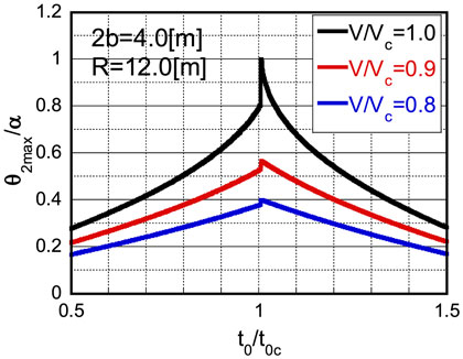
Figure A1. Verification of critical timing: plot of θ2max/α with respect to t0/t0C.
Keywords: earthquake response, near-fault ground motion, double impulse, rigid block, rocking, critical response, overturning, scale effect
Citation: Nabeshima K, Taniguchi R, Kojima K and Takewaki I (2016) Closed-Form Overturning Limit of Rigid Block under Critical Near-Fault Ground Motions. Front. Built Environ. 2:9. doi: 10.3389/fbuil.2016.00009
Received: 21 March 2016; Accepted: 18 April 2016;
Published: 06 May 2016
Edited by:
Solomon Tesfamariam, The University of British Columbia, CanadaReviewed by:
Elias G. Dimitrakopoulos, Hong Kong University of Science and Technology, Hong KongXinzheng Lu, Tsinghua University, China
Hossein Mostafaei, FM Global, USA
Marie-José Nollet, École de technolgie supérieure, Canada
Copyright: © 2016 Nabeshima, Taniguchi, Kojima and Takewaki. This is an open-access article distributed under the terms of the Creative Commons Attribution License (CC BY). The use, distribution or reproduction in other forums is permitted, provided the original author(s) or licensor are credited and that the original publication in this journal is cited, in accordance with accepted academic practice. No use, distribution or reproduction is permitted which does not comply with these terms.
*Correspondence: Izuru Takewaki, takewaki@archi.kyoto-u.ac.jp