 Chara Ch. Mitropoulou
95% of researchers rate our articles as excellent or good
Learn more about the work of our research integrity team to safeguard the quality of each article we publish.
Find out more
ORIGINAL RESEARCH article
Front. Built Environ. , 07 November 2016
Sec. Earthquake Engineering
Volume 2 - 2016 | https://doi.org/10.3389/fbuil.2016.00027
Design of economic structures adequately resistant to withstand during their service life, without catastrophic failures, all possible loading conditions and to absorb the induced seismic energy in a controlled manner, was subjected to intensive research so far. Costly and extremely sensitive equipment, vital in commerce, business, education, and/or health care represent the contents of the contemporary structural systems. Frequently, structures themselves are less valuable than their contents. Moreover, following a catastrophic natural disaster, local communities requires that communication and emergency centers, hospitals, police, and fire stations to be fully operational. In conventional constructions, high floor accelerations are encountered in case of stiff buildings or large interstory drifts in flexible ones. These structural performance characteristics cause difficulties in protecting both building and its contents. As an efficient alternative design practice, base-isolated structures are considered, compared to the conventional fixed-base one. A critical evaluation of optimized fixed and base-isolated reinforced concrete buildings is performed in this study, with respect to the initial and total cost taking into account the life-cycle cost.
According to the contemporary seismic design approaches, structures need to comply with multiple performance-based criteria described for various hazard levels ranging from earthquakes with low intensity and small return period to more destructive events with large return periods. US guidelines (ATC-40, 1996; ASCE/SEI Standard 41-06, 2007), that define the current state of practice, do not differ conceptually and introduce practices and can be considered as a significant diversification from current design codes (EC8, 2004; IBC, 2015), which implement partially performance-based procedures, since they attempt to combine all design criteria to one performance level only, usually that of life safety or collapse prevention. Furthermore, recent advances in the field of computational mechanics and more specifically in design optimization resulted to the transition from the traditional trial and error design procedures to automated ones where powerful search algorithms are used. This is mostly attributed to the progress on metaheuristic search algorithms in the optimization literature.
The design procedure of new seismically isolated buildings is governed by the international building code (IBC-2000) (EC8, 2004) and by the provisions of its predecessor (UBC-97) (UBC, 1997). The design philosophy of IBC-2000 and UBC-97 is that an isolated building should outperform its corresponding fixed-base one, both in moderate and large earthquake events by minimizing the damages of the structural system and its contents. So far, various studies have been presented dealing with the problem of optimum design of base-isolated systems. Constantinou and Tadjbakhsh (1984) considered a linear multistorey structure with a seismic base-isolated system consisting of rubber bearings and frictional elements where the isolation system was optimally designed. Jangid (1996) aiming to define the minimum acceleration of a base-isolated structure investigated the optimum isolation damping, obtained through the minimization of top floor root mean square acceleration. Sorace and Terenzi (2001) applied a non-linear dynamic design procedure of fluid viscous spring-dampers into two case studies. Fragiacomo et al. (2003) studied passive base-isolation systems characterized by a bilinear hysteretic behavior aiming to minimize input energy and displacement of the superstructure. Kim and Roschke (2006) used a genetic algorithm for optimizing of the friction pendulum system. Scruggs et al. (2006) proposed a probability-based active control system where the performance objective was the minimization of the probability of failure. Jangid (2007) investigated an analytical seismic response of multistorey buildings isolated by lead–rubber bearings (LRB) under near-fault motions. Sorace and Terenzi (2008) developed a final experimental campaign to assess the interference of the dissipative actions of the two component devices. Pourzeynali and Zarif (2008) implemented genetic algorithms for finding the optimal values of the parameters of the base-isolation system and simultaneously minimizing the top storey displacement of the building and that of the base-isolation system. Zou (2008) and Zou et al. (2010) presented an optimization technique for the seismic design of base-isolated concrete buildings aiming to minimize the total cost subject to design performance and reliability criteria. Huang and Ren (2011) presented a reliability-based optimization technique for the seismic design of base-isolated structures. Zhang et al. (2011) studied the influence of the action of earthquake to sliding base-isolation structure in order to improve its capacity to reduce by means of optimizing its major parameters. Fujita and Takewaki (2011) presented an efficient methodology to evaluate the robustness of an uncertain base-isolated building; it was shown that the critical combination of the structural parameters can be derived explicitly in order to maximize the approximate objective function by 2nd-order Taylor series expansion. Nemoto et al. (2011) proposed a design method to control the displacement of base-isolation systems using an oil damper that can change its damping properties in accordance to the displacement, while an optimization method was employed to obtain an optimum set of parameters. Murase et al. (2013) investigated a new hybrid passive control system in order to compensate for base-isolated buildings’ deficiencies, where a base-isolated building is connected to another building with oil dampers; as an extension Kasagi et al. (2016) presented an automatic generation algorithm of this kind of smart structures of base-isolation and building-connection hybrid systems. Castaldo and Tubaldi (2015), Castaldo and Ripani (2016), and Castaldo et al. (2016) studied friction pendulum devices aiming to optimize their performance and also to implement seismic fragility and reliability analysis studies.
In this work, an integrated and objective assessment of the performance of multistorey 3D reinforced concrete (RC) buildings is presented, considering fully fixed and base-isolated support conditions. For this purpose, performance-based optimized designs are obtained with respect to minimum initial cost for both types of buildings. The buildings are designed following a non-linear static analysis procedure subject to interstory drift limitations for different hazard levels. The optimized designs are obtained by means of the differential evolution (DE) algorithm.
In construction industry, losses resulting from earthquakes that are possible to occur during the lifespan of a structure require to be taken into account for the case of structural systems situated in seismically active regions when decision-making approaches are implemented. Therefore, life-cycle cost analysis (LCCA) enhanced into an essential part of the design process associated with the future operational cost of structural systems. In early 1960s, LCCA was applied in the commercial area and particularly in the design of products, while LCCA was introduced in construction industry as an investment assessment tool. In this study, LCCA is used for assessing the optimized performance-based designs based on the total cost which accounts for the initial and the life-cycle cost of the structures. LCCA refers to the possible damages caused by earthquake events that might occur during the life span of the structure (Mitropoulou Ch et al., 2011). Therefore, non-linear dynamic analyses are performed for computing the structural response in strong seismic events.
Various base-isolation systems have been implemented so far mainly driven by engineering judgment. Sliding systems such as pure friction type, friction pendulum, sliding isolation pendulum, and resilient friction base systems, represent one category. Elastomeric bearing systems represent a second category, which are constructed with a series of alternating rubber and steel layers. The rubber offers lateral flexibility while steel provides vertical stiffness. Low-damping rubber bearing system belong to the category of elastomeric bearing systems, where the rubber is bonded to the steel end plates, which prevent bulging of the rubber and provide higher vertical stiffness. The elastomeric bearing systems with high-damping natural rubber bearings (HDNR) and the LRB were used in this study. In the case of HDNR systems, the natural rubber compound is used in order to have adequate inherent damping; while in the case of LRB systems, similar to low-damping rubber bearings, a central lead plug is used in order to increase the initial stiffness and energy dissipation capacity of the bearing. Many studies contributed to the evolution of base isolation during the last decades, in particular (Kelly, 1986, 1999; Constantinou et al., 1990; Mokha et al., 1990; Skinner et al., 1992; Nagarajaiah et al., 1993; Naeim and Kelly, 1999; Symans and Constantinou, 1999; Providakis, 2008; Kilar and Koren, 2009; Morgan and Mahin, 2010; Pant et al., 2013; Sorace and Terenzi, 2014; Mazza and Mazza, 2016).
It is common practice to use bilinear constitutive models for simulating isolation bearings, these models are defined by three parameters (K1, K2, and Q) corresponding to the elastic stiffness, the post elastic stiffness, and the characteristic strength (see Figure 1). Parameter K1 is estimated either from hysteretic loops obtained through elastomeric bearing tests or as a multiplier of K2 for lead-plug bearing and friction pendulum-bearing systems. The characteristic strength Q is estimated from hysteresis loops of the elastomeric bearings. In the case of lead-plug bearings, strength Q corresponds to the yield stress of lead core, while in the case of friction pendulum bearings, corresponds to the load carrying capacity of bearing. Furthermore, the non-dimensional characteristic strength α is calculated using the hysteretic properties of the bearing’s material [α = (K1 − K2)/K2] and is an important factor during the design of base-isolation systems.
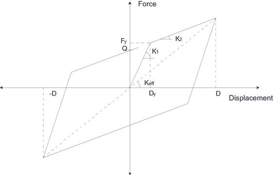
Figure 1. Parameters of basic hysteresis loop of the isolation system.
The design framework followed for base-isolated structures involves a two-stage approach that of the preliminary and the final design one. The demand levels used for the two stages are (i) the design basis earthquake (DBE), referring to hazard level with 10% probability of being exceeded in 50 years and (ii) the maximum considered earthquake (MCE), referring to hazard level with 2% probability of being exceeded in 50 years, respectively.
The preliminary design stage aims to design the isolated structure in such a way that for the DBE will vibrate with fundamental period equal to TD. For this purpose, the damping coefficient BD of the isolation system is selected first (or the damping factor βD that is defined as a function of BD) and the base target displacement DD that is developed by the base-isolated structure for the DBE is calculated as a function of BD and TD (see Eq. 1). TD is defined with a random selection in the range 2.0–3.0 s, since this is the desirable range according to Naeim and Kelly (1999). The definition of DD with reference to TD and BD is given by the following expression:
Next, the effective stiffness of the isolation system KD,max is defined from TD and the lateral forces of the isolation system Vb and the superstructure Vs are calculated as follows:
where RI is a design force reduction factor ranging from 1.4 to 2.0 (Naeim and Kelly, 1999). The structural elements of the superstructure are designed to withstand Vs based on drift constraints (0.010/RI in case of linear static analysis procedure, 0.015/RI in case of response spectrum analysis, or 0.020/RI in case of dynamic time-history analysis). Aiming to resist the gravity loads, lateral loads, and displacement requirements, the design of the isolation system is based on the base displacement DD, stiffness, force, and damping properties of the isolation system. The final design stage is also a trial and error procedure where the force-displacement characteristics of isolation bearings defined during the preliminary design stage are implemented into the numerical model of the structural system. Eigen characteristics of the structure are calculated first, and they are used to define the seismic demand using the MCE. Based on the numerical model and the seismic demand, a series of analysis and designs steps are performed. The targeted final values for the positive (maximum) and negative (minimum) values of the effective stiffness of the structural system are given as follows:
where
Through this trial and error procedure, the characteristics of the isolation systems along with the size of the structural elements are defined. The parameters of isolation systems are compared with those suggested by the prototype bearing test results, in case of difference, the numerical model is revised. In the case of elastomeric isolators, the final design contains additional checks: (i) influence of vertical load on horizontal stiffness and (ii) stability under large lateral displacement.
Structural optimization problems are formulated using constraint and objective functions, usually non-linear functions of the design variables. The expression in mathematical terms of structural optimization problems with reference to design variables, objective, and constraint functions depend on the type of the application. However, many engineering optimization problems are expressed as non-linear programing problems. A mixed continuous-discrete structural optimization problem is formulated as follows:
where s = [sd, sc]T is the vector of design variables of the optimization problem, sd and sc are the vectors of discrete and continuous design variables respectively, gj(s) are equality or inequality constraints, while D and C are the discrete and continuous design sets of size nd and nc, respectively.
Following this general description of the optimization problem, the formulation of the performance-based design optimization problem for fixed-based RC-framed structures used in the current study is defined as follows (Lagaros and Papadrakakis, 2007):
where CIN is the construction cost of structural and non-structural elements, the dimensions of the columns and beams (hi,bi) together with longitudinal steel rebar (reinfi) constitute the discrete and continuous design variables, respectively. , , and denote the maximum interstory drifts developed for the three hazard levels considered (50/50, 10/50, and 2/50), respectively. The limitations of the drift constraints are obtained according to the study by Ghobarah (2004). Similar to the fixed-based formulation the corresponding formulation for the isolated structures is defined as follows:
where, similar to the problem formulation of Eq. 5 CIN is the construction cost of the structural and non-structural elements along with the cost of the isolation systems, while the dimensions of the beams and columns (hi, bi) along with the steel longitudinal reinforcement (reinfi) and the dimensionless characteristic strength a, constitute the discrete and continuous design variables, respectively. The design formulation given in Eq. 6 is also supported by the procedure given in Section “Design Framework.”
During the last decades, multiple search algorithms have been developed to meet the demands of structural design optimization. These algorithms are classified into gradient-based or derivative-free ones. Mathematical programing methods represent the most popular methods of the first category. Heuristic and metaheuristic probabilistic algorithms belong to the second category and are nature-inspired as they are based on the successful behavior of natural systems by learning from nature. In previous studies of the authors, it was found that the DE outperformed other metaheuristic search algorithms (Lagaros and Karlaftis, 2011; Lagaros and Papadrakakis, 2012), and, for this purpose, it is adopted for performing the optimization runs of the structures considered herein.
Differential evolution utilizes a population of NP parameter vectors si,g (i = 1, … , NP) for each generation g. New vectors are generated by adding the weighted difference between two members of the population to a third one. If the resulting vector corresponds to a better design compared to the worst population member, the newly generated vector replaces this member. Several variants of DE have been proposed in the past, one of the most widely used is subsequently presented. In the first step, before defining the ith parameter vector si,g+1, a donor vector vi,g+1 is generated first according to
This is equivalent to the mutation operator of genetic algorithms or evolution strategies. Integers r1, r2, and r3 are selected randomly in the interval [1, NP] while i ≠r1, r2, and r3. In order to control the amplification of the differential variation (sr2,g-sr3,g) the mutation factor F is used, defined in the range [0, 2]. Subsequently, the crossover operator is used that generates the trial vector ui,g+1 = [u1,i,g+1, u2,i,g+1, … , uD,i,g+1]T and is defined from the elements of vectors si,g and vi,g+1, with probability CR as follows:
where randj,i ~ U[0, 1], Irand is a random integer from [1, 2, … , n] ensuring that Vi,g+1 ≠ Si,g, i.e., a certain sequence of the vector elements of u are identical to the elements of v, the other elements of u acquire the original values of si,g. The selection operator corresponds to the last step of the generation phase where vector si,g, is compared to trial vector ui,g+1:
The total cost CTOT of a structural system, refers either to the design-life period of a new structural system or to the remaining life period of an existing or retrofitted one. This cost is defined as a function of design vector s and time, as (Wen and Kang, 2001):
where CIN represents the initial cost of a new or retrofitted structural system, CLC denotes the life-cycle cost in present value; s is the vector of design parameters (i.e., resistance and material characteristics that influence the performance of the system), while t is the time period. The construction cost is referred to with the term “initial cost.” The initial cost is associated to material and labor cost required for the construction. The potential damage cost from earthquakes that may occur during the lifespan of the structure is denoted with the term “life-cycle cost.” It accounts for the damage-repair cost (Cdam), the loss of contents cost due to structural damages that are quantified by the maximum inter-storey drift and due to floor acceleration , the cost of injury recovery (Cinj) or human fatality (Cfat) and other direct or indirect economic losses after an earthquake, related to rental (Cren), and loss of income (Cinc), as shown in
In economic terms, the calculation of losses relies on socioeconomic parameters, and a regularization factor is used for converting costs in present values. The loss of a human life represents the quantity that is the most difficult to justify. There are different approaches for its estimation, ranging from purely economic reasoning to more sensitive ones that consider human loss as irreplaceable. The flowchart of Figure 2 depicts the three steps of the LCCA, while a more details of the calculation procedure can be found in (Lagaros, 2007). In the first step of Figure 2, the characteristics of the problem are defined; i.e., the numerical model, the uncertainties considered and their type, the intensity measure adopted, and the engineering demand parameters used for deriving the capacity curve. Details on the limit states, the basic limit state costs and the limit state parameters can be found in Mitropoulou Ch et al. (2010). In step 2, a number of seismic records are used for each hazard level in order to calculate the response parameters, which are subsequently used in step 3 for calculating CLC for each record.
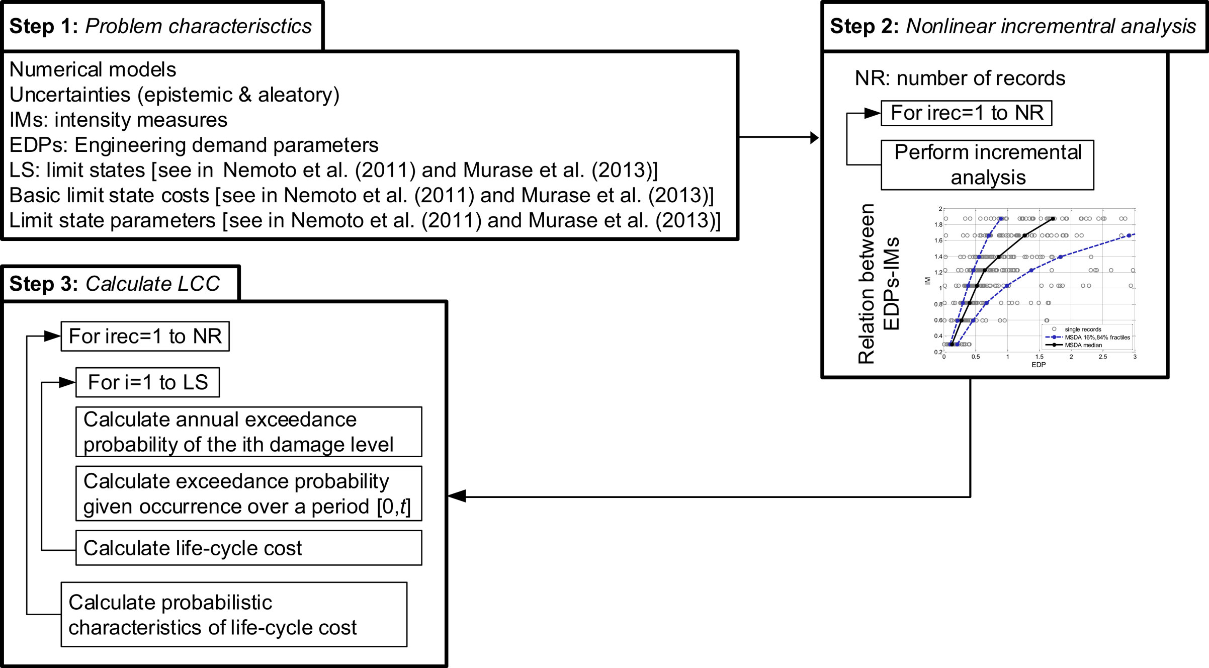
Figure 2. Flowchart of the life-cycle cost analysis calculation procedure [more details in Mitropoulou Ch et al. (2011)].
For the purposes of this study, two test examples shown in Figure 3 are considered: a three- and a six-storey 3D RC building. For each building, the optimized designs were obtained first through the performance-based design formulations presented in Eqs 5 and 6. Then, they are critically assessed with respect to their initial and total cost taking into account the life-cycle cost of the optimized structures. More specifically, the test examples are optimally designed considering both fixed support and base-isolated conditions. In the latter case, LRB and HDNR isolation systems are implemented.
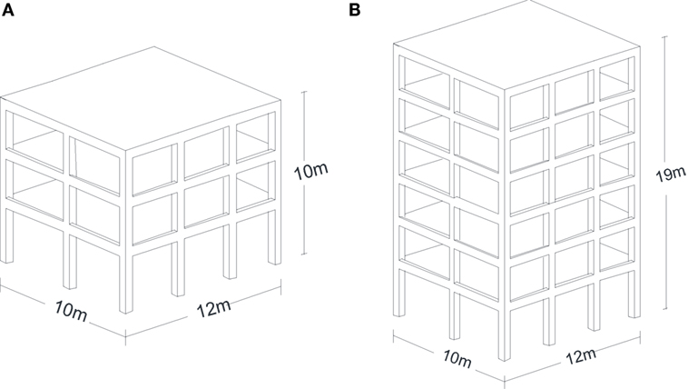
Figure 3. 3D view of (A) the three-storey and (B) the six-storey test example.
Concrete of class C20/25 (nominal cylindrical strength of 20 MPa) and class S500 steel (nominal yield stress of 500 MPa) are assumed. Slab thickness of 18 cm is considered, contributing to the beams moment of inertia with an effective flange width. Due to floor finishing and partitions, distributed dead load of 2 kN/m2 is considered further to self-weight of beams and slabs, together with 1.5 kN/m2 live load. These loads are combined with gravity loads (persistent design situation), and load factor multipliers of 1.35 and 1.5 for nominal dead and live loads, respectively, are implemented. According to the seismic design combination, dead loads are considered with their nominal value, while live loads with 30% of their nominal value.
In case of fixed-based RC buildings target displacement for each hazard level is calculated using the target displacement method and the response spectrums for the three corresponding hazard levels; with 2, 10, and 50% probability of exceedance (Somerville and Collins, 2002). Base shear is obtained from EC8 elastic response spectrum for soil type B (characteristic periods TB = 0.15 s and TD = 2.00 s), while the importance factor γI was taken equal to 1.0. Peak ground acceleration (PGA) is taken from Table 1 for three hazard levels with 2, 10, and 50% probability of exceedance in 50 years. The response spectrum for the fixed, HDNR and LRB isolations was used for damping factors β = 5%, β = 10%, β = 20%, respectively. In this study, three sets of natural records are used, i.e., sets with their longitudinal and their transverse components, selected from the database of Somerville and Collins (2002). The basic characteristics of these records are provided in Tables 2–4 corresponding to the three hazard levels, 50, 10, and 2% in 50 years, respectively. A strength reduction factor of 0.75 was used for both fixed-base system and the superstructure of the seismically isolated one, while the behavior factor of the structure q for both systems was taken equal to 1.0.
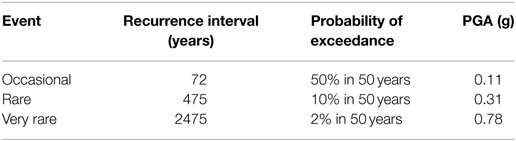
Table 1. PGA according to the frequency of the seismic hazard.
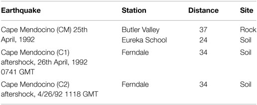
Table 2. Natural records representing the 50% in 50-year hazard level (Somerville and Collins, 2002).
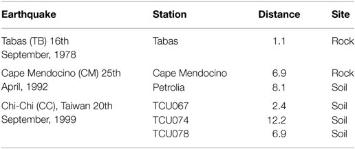
Table 3. Natural records representing the 10% in 50-year hazard level (Somerville and Collins, 2002).
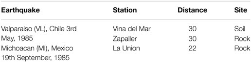
Table 4. Natural records representing the 2% in 50-year hazard level (Somerville and Collins, 2002).
In regions where inelastic deformations are expected to develop, non-linear static or dynamic analyses are implemented requiring specialized numerical simulation like the plastic-hinge or fiber approaches. The first one, although computationally efficient, has limitations with respect to the accuracy compared to the fiber approach. According to the later one, each structural element is discretized into integration sections and each section is divided into fibers having specific material properties (concrete, structural steel, or steel reinforcement). The sections are located at the Gaussian integration points of the elements. The main advantage of fiber approach is that every fiber has a simple uniaxial material model allowing a simple implementation of inelastic behavior subjected to dynamic loading (Lagaros and Fragiadakis, 2011).
OpenSEES software platform (McKenna and Fenves, 2001) was used for performing all analyses. Each structural element was modeled with one force-based, fiber beam-column element. The simulation of concrete fibers is based on the modified Kent–Park model, where the monotonic envelope of concrete in compression follows the model of Kent and Park (1971) as extended by Scott et al. (1982). This model was chosen due to its ability to predict with acceptable accuracy the demand for flexure-dominated RC members. The Menegotto–Pinto model (Menegotto and Pinto, 1973) was used for simulating the transient behavior of the reinforcing bars neglecting the effects of shear and bond-slip. Second-order effects are considered using the complete geometric stiffness matrix. The simulation of the bearings was implemented using zero length elements with a uniaxial material law with linear kinematic and isotropic hardening.
Based on previous studies by the authors (Lagaros and Karlaftis, 2011; Lagaros and Papadrakakis, 2012), the DE optimization algorithm was found to be superior, and, for this reason, it is selected for solving the optimization problem at hand. Based on a parameter study in Pedersen (2010) the parameters used for DE algorithm are as follows: the population size NP = 100, the probability CR = 0.90, the constant F = 0.47 and the control variable λ = 0.2. The simple, yet effective, multiple linear segment penalty function (Lagaros, 2014) is used in this study for handling the constraints. According to this technique if no violation is detected, then no penalty is implemented to the objective function. If any of the constraints is violated, a penalty factor is applied to the objective function, controlled by the degree of constraints’ violation. The optimization procedure is terminated when the best value of the objective function in the last 20 generations remains unchanged.
The dimensions of the design components (i.e., columns, beams, steel reinforcement, and dimensions of the bearings) are presented in Tables 5 and 6. Element group 1 in the three-storey buildings refers to the four corner columns, group 2 to all other external columns, and group 3 to the internal columns (see Figure 4A). The same element groups refer to the lower three levels of the six-storey building, while in the upper three levels the element groups are 4, 5, and 6, respectively. For both test examples, the cross-section x refer to the horizontal beams and the cross-section y to the vertical ones (see Figure 4B). The initial cost of the optimized designs for the fixed and the isolated buildings is presented in Table 7.
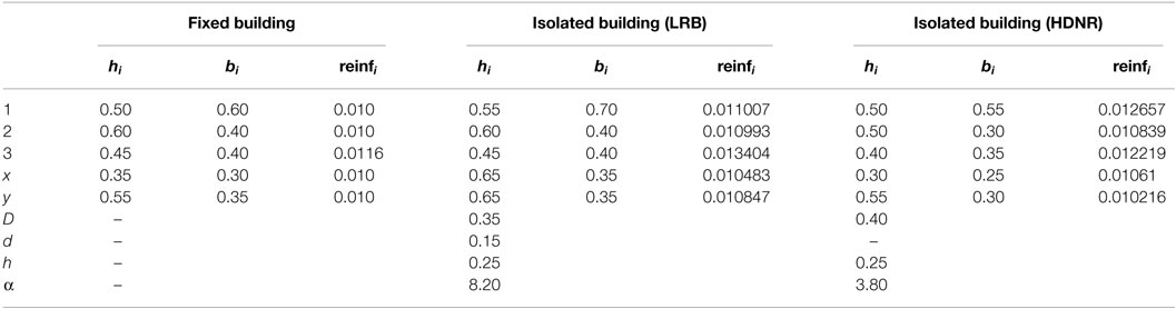
Table 5. Dimensions of the structural elements of the three-storey fixed RC fame (in meters).
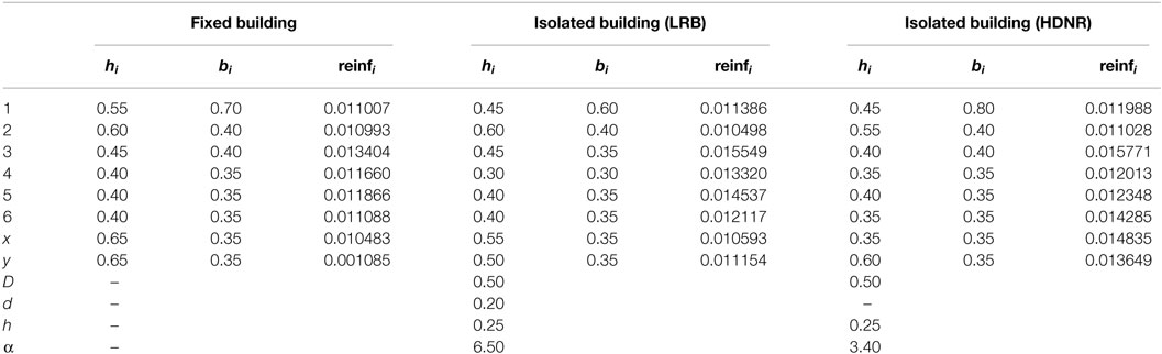
Table 6. Dimensions of the structural elements of the six storey fixed RC frame (in meters).
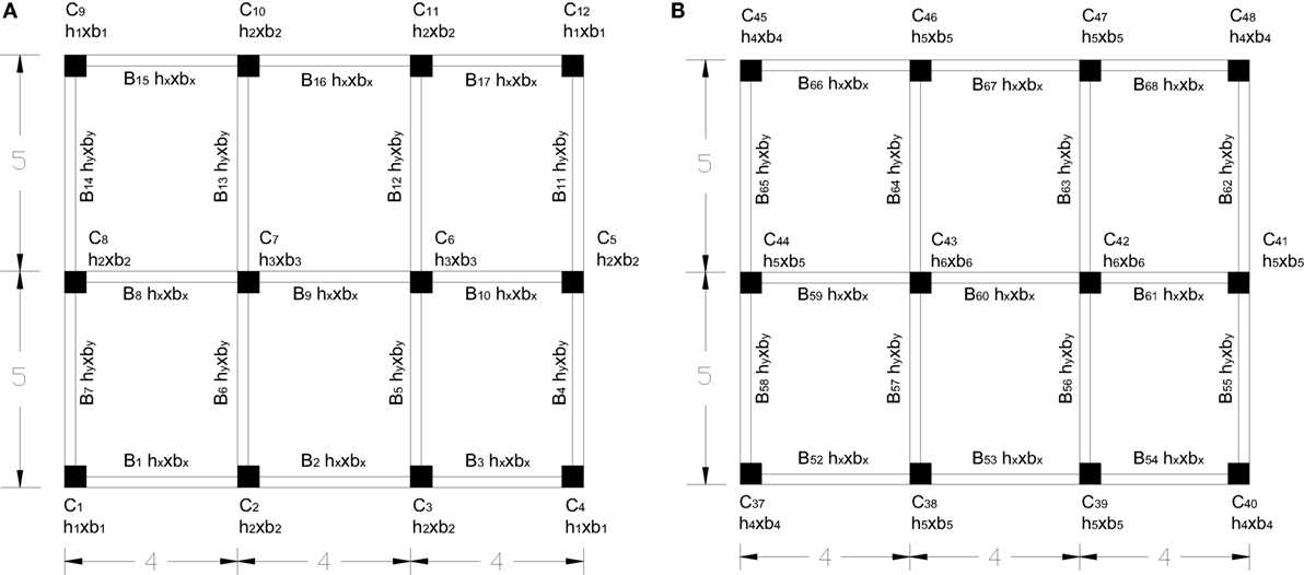
Figure 4. Six-storey test example – plan of the (A) first and (B) second level of the building.
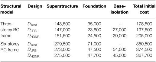
Table 7. Initial cost of the optimum designs (in MU).
Figures 5–7 depict the time histories of the roof acceleration of the fixed and isolated three-storey buildings. Comparing the results of the analysis, as expected, significant decrease on the maximum floor accelerations is observed in the base-isolated buildings. As far as the maximum interstory drift is concerned, the reduction observed for the design with LRB isolation system (DLRB), compared to the fixed design (Dfixed), is almost the same with that observed with HDNR isolation system (DHDRN). It can be seen observed that the two isolated structures exhibit a more flexible response with lower acceleration frequency and amplitude compared to the fixed structure. This leads to a significant reduction in the seismic design forces and hence to reduced risk of structural and non-structural damages. Figures 8–10 depict the maximum roof drifts of the three-storey buildings where the use of seismic isolation system leads to reduced drift values for the superstructure, especially for the case of the 2/50 hazard level seismic records. It is worth mentioning also that for both DLRB and DHDRN designs the interstory drift has a uniform distribution trend at each floor while for the case of Dfixed the interstory drift presents a reduced trend from bottom to roof.
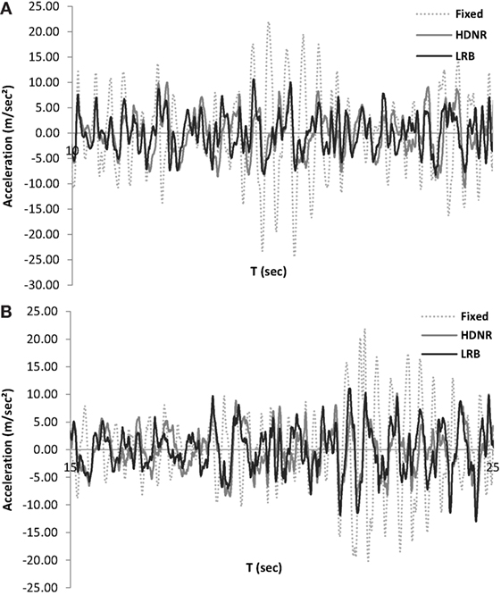
Figure 5. Three-storey test example – roof acceleration time history of the fixed and isolated buildings along the (A) x and (B) y directions (Michoacan, Mexico, La Union record, of the 2/50 hazard level, Table 4).
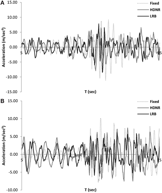
Figure 6. Three-storey test example – roof acceleration time history of the fixed and isolated buildings along the (A) x and (B) y directions (Tabas record, of the 10/50 hazard level, Table 3).
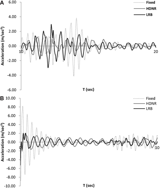
Figure 7. Three Three-storey test example – roof acceleration time history of the fixed and isolated buildings along the (A) x and (B) y directions (Cape Mendocino, Ferndale-C1 record, of the 50/50 hazard level, Table 2).
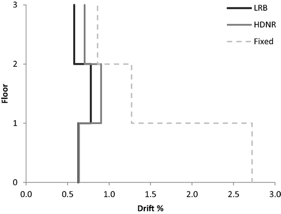
Figure 8. Three-storey test example – maximum interstory drifts of the fixed and isolated buildings (Michoacan, Mexico, La Union record of the 2/50 hazard level, Table 4).
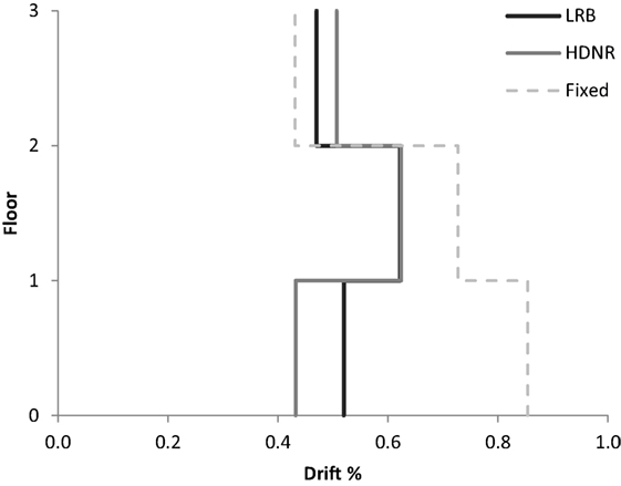
Figure 9. Three-storey test example – maximum interstory drifts of the fixed and isolated buildings (Chi–Chi, Taiwan, TCU078 of the 10/50 hazard level, Table 3).
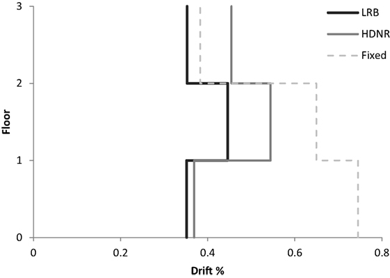
Figure 10. Three-storey test example – maximum interstory drifts of the fixed and isolated buildings (Cape Mendocino (C1), Ferndale record of the 50/50 hazard level, Table 2).
Figures 11–13 demonstrate for the three seismic hazard levels (2/50, 10/50, and 50/50) the maximum values of the interstory drifts as well as the maximum values of the roof accelerations for the six-storey test example. Comparing the results obtained for the isolated structures with those of the fixed structure, significant decrease of the maximum interstory drift and acceleration is observed. As far as the maximum roof acceleration is concerned, the reduction observed for DHDNR is more significant compared to that observed for DLRB. Similar to this observation for the case of the three-storey test example, the two isolated designs present a more flexible response with lower frequency and acceleration amplitude compared to the fixed structure. Figures 14–16 show the maximum roof drifts of the six-storey buildings. The results obtained for this example verify quantitatively that seismic isolation highly reduces the drifts of the superstructure, especially for the use of HDNR isolators, particularly in the case of strong earthquakes (2/50). It is also observed that in 2/50 hazard level the maximum floor acceleration is distributed uniformly along height in the case of DLRB. Thus, it can be said that with reference to maximum floor acceleration the use of base isolation becomes more active in the case of strong ground motions (i.e., 2/50 hazard level), especially in the case of LRB, because they are characterized by a higher damping capacity as compared to HDNR bearings.
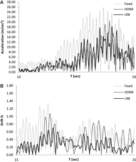
Figure 11. Six-storey test example – (A) roof floor acceleration and (B) roof drift time histories of the fixed and isolated buildings for the Valparaiso, Chile, Vina del Mar record (2/50 hazard level, Table 4).
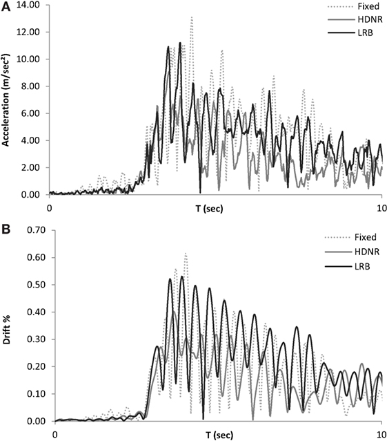
Figure 12. Six-storey test example – (A) roof floor acceleration and (B) roof drift time histories of the fixed and isolated buildings for the Cape Mendocino, Petrolia record (10/50 hazard level, Table 3).
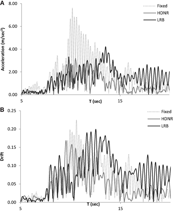
Figure 13. Six-storey test example – (A) roof floor acceleration and (B) roof drift time histories of the fixed and isolated buildings for the Cape Mendocino, Butler Valley record (50/50 hazard level, Table 2).
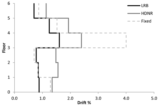
Figure 14. Six-storey test example – maximum interstory drifts of the fixed and isolated buildings (for the bin of records of the 2/50 hazard level, Table 4).
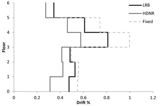
Figure 15. Six-storey test example – maximum interstory drifts of the fixed and isolated buildings (for the bin of records of the 10/50 hazard level, Table 3).
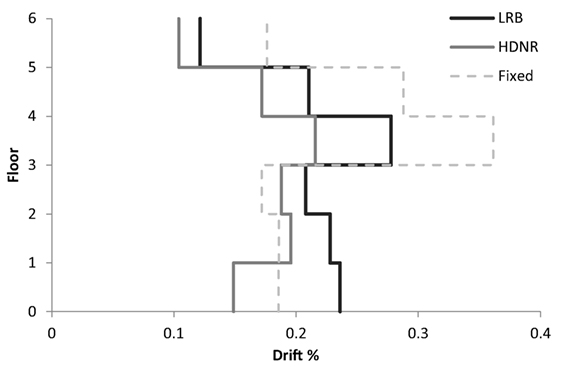
Figure 16. Six-storey test example – maximum interstory drifts of the fixed and isolated buildings (for the bin of records of the 50/50 hazard level, Table 2).
In this part of the study, the optimized designs are assessed by means of LCCA. For this purpose, the values of the maximum interstory drifts and floor accelerations need to be calculated for three hazard levels (2/50, 10/50, and 50/50). The structural performance of each optimized design and for each hazard level is obtained by means of multi-stripe incremental dynamic analysis (Mitropoulou Ch et al., 2011) using scaled natural records for each hazard level (see Tables 2–4); relying on SA(T1, 5%) of the Eurocode 8 response spectrum for each hazard level, respectively. The relative scale of records’ two components is preserved implementing the following procedure, the record’s component with the highest SA(T1, 5%) is scaled first, and the same scaling factor is assigned to the second component in order to preserve their relative ratio. For the calculation of the initial construction cost, that includes concrete and steel reinforcement material cost, labor cost, as well as the non-structural component cost; it was assumed that the concrete cost is 100 MU/m3, the steel reinforcement cost is 2.5 MU/kg, while the infill and bearing costs are 35 MU/m2 and 60 MU/lt, respectively; given in monetary units (MU, corresponding to Euros or Dollars).
In case of retrofit interventions, the cost component of an added reaction wall needs to be included in the construction cost for a base-isolated structure. Moreover, it should also be mentioned that for the retrofit application to a base-isolated structure the costs largely depends on the presence or not of an existing underground (basement, garage) story; and that the costs of installation or replacement of HNRB isolators can significantly differ from those of LRB isolators, not only in terms of price of the devices, but also for the different types of equipment to be used for the installation or removal.
Figure 17 depicts the total cost breakdown of the optimized designs of the three-storey buildings (Dfixed, DHDNR and DLRB), along with the life-cycle cost components calculated based on the drift limits given in Ghobarah (2004). It can be seen in Figure 17, that DHDNR is 9% cheaper compared to DLRB and 17% cheaper compare to Dfixed, with reference to the life-cycle cost, while DLRB is by 9% cheaper compared to Dfixed. Figure 18 shows the contribution of initial and life-cycle cost components to the total life-cycle cost. The initial cost (CIN) represents the 52% of the total cost for Dfixed, while for DLRB and DHDRN represents the 57 and 60%, respectively. The dominant contributor for all designs is the initial cost; the second dominant contributor is the loss of contents due to floor acceleration, while the third dominant contributor is damage/repair cost. CIN for the Dfixed design is 10% lower than DHDNR, and 13% lower than DLRB. Worth mentioning is that the loss of contents components is four times that of the repair cost; while, the loss of contents contribution due to the maximum interstory drift is insignificant compared to the losses due to the floor acceleration. It appears that the injury (minor/major) and fatality costs represent a minor part of the total cost for all three designs (less than 0.1%). Comparing the three designs with reference to the total cost it can be seen that they are almost the same.
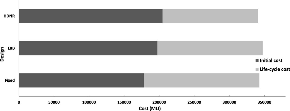
Figure 17. Three-storey test example – contribution of the initial cost and life-cycle cost components to the total cost for different types of foundation.
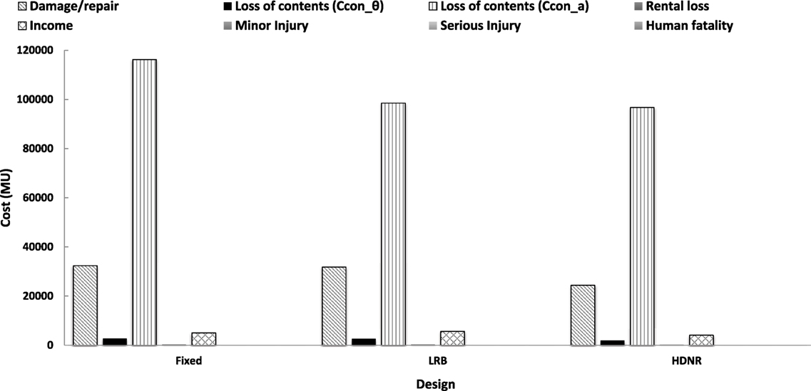
Figure 18. Three-storey test example – life-cycle cost components for different types of foundation.
The results obtained for the six storey building are shown in Figure 19 regarding the optimized designs obtained with reference to the type of foundation (Dfixed, DHDNR, and DLRB), along with the life-cycle cost components. The initial cost represents the 54% of the total cost for Dfixed while for DLRB and DHDRN represents the 66 and 72%, respectively. In term of the life-cycle cost DHDNR and DLRB are 51 and 34% cheaper compared to Dfixed while DHDNR is 25% cheaper compared to DLRB. Figure 20 shows the contribution of initial and life-cycle cost components to total life-cycle cost. Although the initial cost is the dominant contributor for all designs, in the case of the life-cycle cost components the dominant contributor for all designs is the loss of contents due to floor acceleration, while damage/repair cost represents the second dominant contributor. Similar to the previous test example, the loss of contents components is four times that of the repair cost. The numerical results for this example confirms the observation obtained for the three-storey building that the loss of contents due to maximum interstory drift is not significant compared to that of the floor acceleration while the injury cost and the fatality costs represent only a small portion of the total cost for all three designs (less than 0.1%). More specifically, comparing Dfixed, DHDNR, and DLRB with reference to CIN, it can be seen that Dfixed is 5 and 7% cheaper compared to the two isolated designs, respectively; while DHDNR is cheaper 2% compared to the DLRB. Comparing the three designs with reference to the total cost it can be seen that contrary to the observations reported for the three-storey test example they vary significantly. In particular, Dfixed is 13 and 21% more expensive compared to the DLRB and DHDNR designs, respectively.
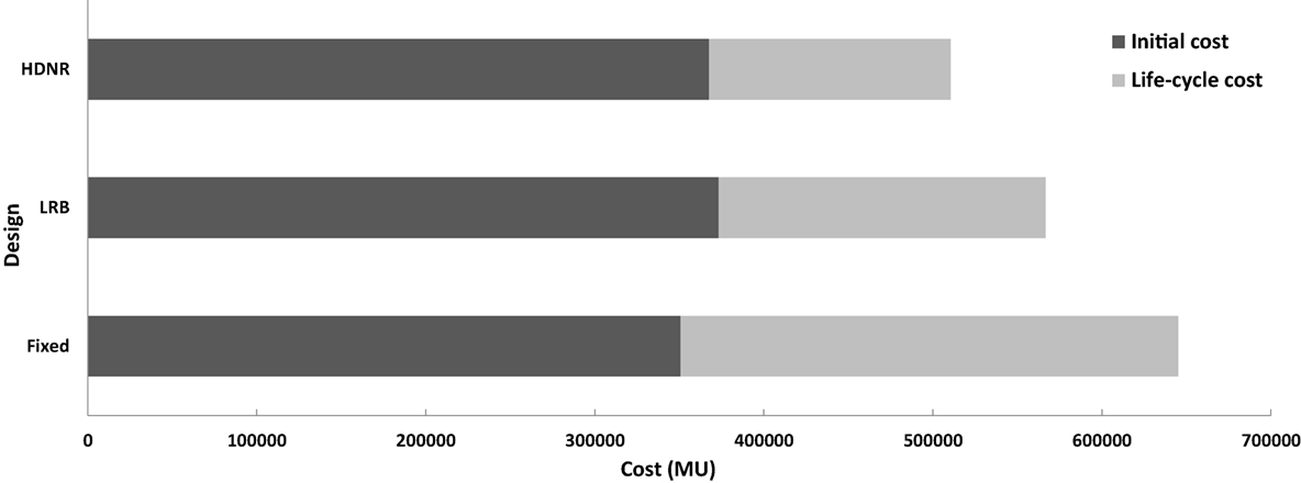
Figure 19. Six-storey test example – contribution of the initial cost and life-cycle cost components to the total cost for different types of foundation.
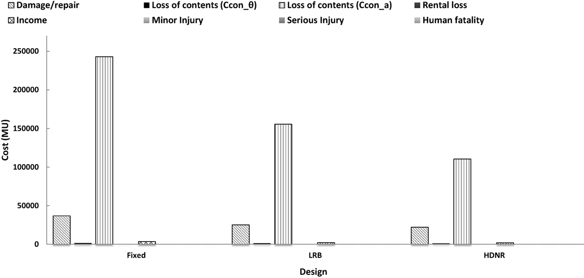
Figure 20. Six-storey test example – life-cycle cost components for different types of foundation.
The performance of 3D RC buildings designed with fixed or base-isolation support conditions is assessed on the basis of a total cost criterion where both the initial cost and the life-cycle cost are considered. For the purposes of this study, a three- and a six-storey RC building is considered. In order to achieve an objective assessment of the performance of the two buildings, they are designed via a performance-based optimum design formulation taking into consideration the initial cost and maximum interstory drift performance constraints of the superstructure assessed for different hazard levels. More specifically, both test examples are optimally designed considering fixed as well as base-isolated support conditions with both LRB and HDNR isolation systems. The numerical results depict significant decrease in terms of the maximum interstory drift and floor accelerations for the base-isolated models.
Furthermore, it is demonstrated that the isolated structures present more flexible response where the frequency of the acceleration motion is lower compared to that of the fixed structure. The initial cost of the isolated structure with LRB is less compared to that of the corresponding with HDNR. Both isolation systems are considerably more expensive than the fixed support building in terms of initial cost. However, when the life-cycle cost is taken into consideration, then base-isolated buildings provide a more economical alternative to the fixed support one, particularly when LRB are used. It appears that the most dominant cost for all designs is the loss of contents due to floor acceleration, while damage/repair cost represents the next dominant cost contributor. Worth mentioning also that the loss of contents cost due to the maximum interstory drift is insignificant compared to that associated with the floor accelerations. In all test cases, injury (minor/major) and fatality costs represent an insignificant part of the total cost. The numerical test also demonstrated that between the two base-isolated structures the one with the HDNR is cheaper than the one with LRB.
The manuscript was written through contributions of all the authors. All the authors have given approval to the final version of the manuscript.
The authors declare that the research was conducted in the absence of any commercial or financial relationships that could be construed as a potential conflict of interest.
This research has been financed by the State Scholarships Foundation-IKY for supporting Post-doctoral studies – Research Funding Program: “Multicriteria Design of RC Structures based on Economy, Strength and Energy-Ecological Efficiency”.
ASCE/SEI Standard 41-06. (2007). Seismic Rehabilitation of Existing Buildings, Prepublication Edition. Reston, VA, USA: Structural Engineering Institute, American Society of Civil Engineers (ASCE).
ATC-40. (1996). Seismic Evaluation and Retrofit of Concrete Buildings. Redwood City, USA: Applied Technology Council (ATC).
Castaldo, P., Amendola, G., and Palazzo, B. (2016). Seismic fragility and reliability of structures isolated by friction pendulum devices: seismic reliability-based design. Earthq. Eng. Struct. Dyn. doi:10.1002/eqe.2798
Castaldo, P., and Ripani, M. (2016). Optimal design of friction pendulum system properties for isolated structures considering different soil conditions. Soil Dyn. Earthq. Eng. 90, 74–87. doi:10.1016/j.soildyn.2016.08.025
Castaldo, P., and Tubaldi, E. (2015). Influence of FPS bearing properties on the seismic performance of base-isolated structures. Earthq. Eng. Struct. Dyn. 44, 2817–2836. doi:10.1002/eqe.2610
Constantinou, M., Mokha, A., and Reinhorn, A. (1990). Teflon bearings in base isolation II: modeling. J. Struct. Eng. 116, 455–474. doi:10.1061/(ASCE)0733-9445(1990)116:2(455)
Constantinou, M. C., and Tadjbakhsh, I. G. (1984). Optimum design of a base isolation system with frictional elements. Earthq. Eng. Struct. Dyn. 12, 203–214. doi:10.1002/eqe.4290120205
EC8. (2004). Eurocode 8: Design of Structures for Earthquake Resistance. Brussels, Belgium: European Committee for Standardization. The European Standard EN 1998-1.
Fragiacomo, M., Rajgelj, S., and Cimadom, F. (2003). Design of bilinear hysteretic isolation systems. Earthq. Eng. Struct. Dyn. 32, 1333–1352. doi:10.1002/eqe.276
Fujita, K., and Takewaki, I. (2011). Earthquake response bound analysis of uncertain base-isolated buildings for robustness evaluation. J. Struct. Constr. Eng. 76, 1453–1460. doi:10.3130/aijs.76.1453
Ghobarah, A. (2004). “On drift limits associated with different damage levels,” in Proceedings of the International Workshop on Performance-Based Seismic Design: Concepts and Implementation, Bled, Slovenia, PEER Report 2004/05, eds P. Fajfar and H. Krawinkler (Berkeley: Pacific Earthquake Engineering Research Center, College of Engineering, University of California), 321–332.
Huang, T.-L., and Ren, W.-X. (2011). Dynamic reliability-based seismic optimal design of base-isolated structures. Adv. Mater. Res. 243-249, 3765–3769. doi:10.4028/www.scientific.net/AMR.243-249.3765
IBC. (2015). International Code Council (ICC), Seismically Isolated Structures. Country Club Hills, IL, USA: International Building Code (IBC).
Jangid, R. S. (1996). Optimum damping in a non-linear base isolation system. J. Sound Vib. 189, 477–487. doi:10.1006/jsvi.1996.0030
Jangid, R. S. (2007). Optimum lead-rubber isolation bearings for near-fault motions. Eng. Struct. 29, 2503–2510. doi:10.1016/j.engstruct.2006.12.010
Kasagi, M., Fujita, K., Tsuji, M., and Takewaki, I. (2016). Automatic generation of smart earthquake-resistant building system: hybrid system of base-isolation and building-connection. Heliyon 2, e00069. doi:10.1016/j.heliyon.2016.e00069
Kelly, J. M. (1986). Aseismic base isolation: review and bibliography. Soil Dyn. Earthq. Eng. 5, 202–216. doi:10.1016/0267-7261(86)90006-0
Kelly, J. M. (1999). The role of damping in seismic isolation. Earthq. Eng. Struct. Dyn. 28, 3–20. doi:10.1002/(SICI)1096-9845(199901)28:1<3::AID-EQE801>3.3.CO;2-4
Kent, D. C., and Park, R. (1971). Flexural members with confined concrete. J. Struct. Div. 97, 1969–1990.
Kilar, V., and Koren, D. (2009). Seismic behaviour of asymmetric base isolated structures with various distributions of isolators. Eng. Struct. 31, 910–921. doi:10.1016/j.engstruct.2008.12.006
Kim, H.-L., and Roschke, P. N. (2006). Design of fuzzy logic controller for smart base isolation system using genetic algorithm. Eng. Struct. 28, 84–96. doi:10.1016/j.engstruct.2005.07.006
Lagaros, N. D. (2007). Life-cycle cost analysis of construction practices. Bull. Earthq. Eng. 5, 425–442. doi:10.1007/s10518-007-9038-1
Lagaros, N. D. (2014). A general purpose real-world structural design optimization computing platform. Struct. Multidiscipl. Optim. 49, 1047–1066. doi:10.1007/s00158-013-1027-1
Lagaros, N. D., and Fragiadakis, M. (2011). “Evaluation of static pushover methods for performance-based optimum,” in 3rd International Conference on Computational Methods in Structural Dynamics and Earthquake Engineering, COMPDYN 25-28 May 2011 (Corfu, Greece). Available at: http://eccomasproceedings.org/
Lagaros, N. D., and Karlaftis, M. G. (2011). A critical assessment of metaheuristics for scheduling emergency infrastructure inspections. Swarm Evol. Comput. 1, 147–163. doi:10.1016/j.swevo.2011.06.002
Lagaros, N. D., and Papadrakakis, M. (2007). Seismic design of RC structures: a critical assessment in the framework of multi-objective optimization. Earthq. Eng. Struct. Dyn. 36, 1623–1639. doi:10.1002/eqe.707
Lagaros, N. D., and Papadrakakis, M. (2012). Applied soft computing for optimum design of structures. Struct. Multidiscipl. Optim. 45, 787–799. doi:10.1007/s00158-011-0741-9
Mazza, F., and Mazza, M. (2016). Nonlinear seismic analysis of irregular r.c. framed buildings base-isolated with friction pendulum system under near-fault excitations. Soil Dyn. Earthq. Eng. 90, 299–312. doi:10.1016/j.soildyn.2016.08.028
McKenna, F., and Fenves, G. L. (2001). The OpenSees Command Language Manual – Version 1.2. Berkeley, USA: Pacific Earthquake Engineering Research Centre, University of California.
Menegotto, M., and Pinto, P. E. (1973). “Method of analysis for cyclically loaded reinforced concrete plane frames including changes in geometry and non-elastic behaviour of elements under combined normal force and bending,” in Proceedings, IABSE Symposium on Resistance and Ultimate Deformability of Structures Acted on by Well Defined Repeated Loads (Zürich), 15–22.
Mitropoulou Ch, C., Lagaros, N. D., and Papadrakakis, M. (2010). Building design based on energy dissipation: a critical assessment. Bull. Earthq. Eng. 8, 1375–1396. doi:10.1007/s10518-010-9182-x
Mitropoulou Ch, C., Lagaros, N. D., and Papadrakakis, M. (2011). Life-cycle cost assessment of optimally designed reinforced concrete buildings under seismic actions. Reliab. Eng. Syst. Saf. 96, 1311–1331. doi:10.1016/j.ress.2011.04.002
Mokha, A., Constantinou, M., and Reinhorn, A. (1990). Teflon bearings in base isolation I: testing. J. Struct. Eng. 116, 438–454. doi:10.1061/(ASCE)0733-9445(1990)116:2(438)
Morgan, T. A., and Mahin, S. A. (2010). Achieving reliable seismic performance enhancement using multi-stage friction pendulum isolators. Earthq. Eng. Struct. Dyn. 39, 1443–1461. doi:10.1002/eqe.1043
Murase, M., Tsuji, M., and Takewaki, I. (2013). Smart passive control of buildings with higher redundancy and robustness using base-isolation and inter-connection. Earthq. Struct. 4, 649–670. doi:10.12989/eas.2013.4.6.649
Naeim, F., and Kelly, J. M. (1999). Design of Seismic Isolated Structures – From Theory to Practice. New York: John Wiley.
Nagarajaiah, S., Reinhorn, A. M., and Constantinou, M. C. (1993). Torsion in base-isolated structures with elastomeric isolation systems. J. Struct. Eng. 119, 2932–2951. doi:10.1061/(ASCE)0733-9445(1993)119:1(130)
Nemoto, M., Ikago, K., Ikenaga, M., and Inoue, N. (2011). A design method of a base isolated system for detached houses using variable oil dampers. J. Struct. Constr. Eng. 76, 291–299. doi:10.3130/aijs.76.291
Pant, D. R., Wijeyewickrema, A. C., and Elgawady, M. A. (2013). Appropriate viscous damping for nonlinear time-history analysis of base-isolated reinforced concrete buildings. Earthq. Eng. Struct. Dyn. 42, 2321–2339. doi:10.1002/eqe.2328
Pedersen, M. E. H. (2010). Good Parameters for Differential Evolution. Technical Report No.: HL1002. Southampton: Hvass Laboratories.
Pourzeynali, S., and Zarif, M. (2008). Multi-objective optimization of seismically isolated high-rise building structures using genetic algorithms. J. Sound Vib. 311, 1141–1160. doi:10.1016/j.jsv.2007.10.008
Providakis, C. P. (2008). Effect of LRB isolators and supplemental viscous dampers on seismic isolated buildings under near-fault excitations. Eng. Struct. 30, 1187–1198. doi:10.1016/j.engstruct.2007.07.020
Scott, B. D., Park, R., and Priestley, M. J. N. (1982). Stress–strain behavior of concrete confined by overlapping hoops at low and high strain rates. ACI J. 79, 13–27.
Scruggs, J. T., Taflanidis, A. A., and Beck, J. L. (2006). Reliability-based control optimization for active base isolation systems. Struct. Contr. Health Monit. 13, 705–723. doi:10.1002/stc.107
Skinner, R. I., Robinson, W. H., and McVerry, G. H. (1992). An Introduction to Seismic Isolation. New York, NY: John Wiley & Sons Ltd.
Somerville, P., and Collins, N. (2002). Ground Motion Time Histories for the Humboldt Bay Bridge. Pasadena, CA: URS Corporation. Available at: http://peer.berkeley.edu/research/peertestbeds/Hbt/HumboldtBayBridgeReport.pdf
Sorace, S., and Terenzi, G. (2001). Non-linear dynamic design procedure of FV spring-dampers for base isolation – frame building applications. Eng. Struct. 23, 1568–1576. doi:10.1016/S0141-0296(01)00064-5
Sorace, S., and Terenzi, G. (2008). Analysis and demonstrative application of a base isolation/supplemental damping technology. Earthq. Spectra 24, 775–793. doi:10.1193/1.2946441
Sorace, S., and Terenzi, G. (2014). Motion control-based seismic retrofit solutions for a R/C school building designed with earlier technical standards. Bull. Earthq. Eng. 12, 2723–2744. doi:10.1007/s10518-014-9616-y
Symans, M. D., and Constantinou, M. C. (1999). Semi-active control systems for seismic protection of structures: a state-of-the-art review. Eng. Struct. 21, 469–487. doi:10.1016/S0141-0296(97)00225-3
UBC. (1997). International Conference of Building Officials, Earthquake Regulations for Seismic-Isolated Structures. Whittier, CA, USA: Uniform Building Code (UBC).
Wen, Y. K., and Kang, Y. J. (2001). Minimum building life-cycle cost design criteria. I: methodology. J. Struct. Eng. 127, 330–337. doi:10.1061/(ASCE)0733-9445(2001)127:3(330)
Zhang, Y., Wang, Y., and Shi, Y. (2011). Parameters optimization of sliding base-isolation structure under the action of coupling earthquake. Adv. Mater. Res. 24, 4021–4027. doi:10.4028/www.scientific.net/AMR.243-249.4021
Zou, X.-K. (2008). Integrated design optimization of base-isolated concrete buildings under spectrum loading. Struct. Multidiscipl. Optim. 36, 493–507. doi:10.1007/s00158-007-0184-5
Keywords: base isolation, performance-based design, structural optimization, probabilistic life-cycle cost analysis, dynamic loading, metaheuristics
Citation: Mitropoulou CC and Lagaros ND (2016) Life-Cycle Cost Model and Design Optimization of Base-Isolated Building Structures. Front. Built Environ. 2:27. doi: 10.3389/fbuil.2016.00027
Received: 16 August 2016; Accepted: 20 October 2016;
Published: 07 November 2016
Edited by:
Fabio Mazza, University of Calabria, ItalyReviewed by:
Gloria Terenzi, University of Florence, ItalyCopyright: © 2016 Mitropoulou and Lagaros. This is an open-access article distributed under the terms of the Creative Commons Attribution License (CC BY). The use, distribution or reproduction in other forums is permitted, provided the original author(s) or licensor are credited and that the original publication in this journal is cited, in accordance with accepted academic practice. No use, distribution or reproduction is permitted which does not comply with these terms.
*Correspondence: Nikos D. Lagaros, nlagaros@central.ntua.gr
Disclaimer: All claims expressed in this article are solely those of the authors and do not necessarily represent those of their affiliated organizations, or those of the publisher, the editors and the reviewers. Any product that may be evaluated in this article or claim that may be made by its manufacturer is not guaranteed or endorsed by the publisher.
Research integrity at Frontiers
Learn more about the work of our research integrity team to safeguard the quality of each article we publish.