Syn-thrusting polygonal normal faults exposed in the hinge of the Cingoli anticline, northern Apennines, Italy
 Lorenzo Petracchini
 Marco Antonellini
 Andrea Billi
 Davide Scrocca
- 1Istituto di Geologia Ambientale e Geoingegneria, Consiglio Nazionale delle Ricerche, Rome, Italy
- 2Dipartimento di Scienze Biologiche, Geologiche e Ambientali, Bologna University, Bologna, Italy
The Cingoli arcuate anticline is part of the Apennines fold-thrust belt in Italy. The anticline involves sedimentary carbonate strata generally affected by syn-thrusting contractional structures such as bed-normal pressure solution seams, folds, and reverse faults. An exception is constituted by an outcrop in the anticline hinge, where sub-horizontal carbonate and chert beds are affected by joints and intraformational short normal faults. These faults are poorly-systematic and conceivably polygonal in map view. They cut through the carbonate beds while usually stop against the chert layers that are bent and extended along the faults themselves. At the fault tips, the displacement is generally transferred, via a lateral step, to an adjacent similar fault segment. The fault surfaces are often characterized by slickolites, greenish clayey residue, and micro-breccias including chert and carbonate clasts. Fault displacement is partly or largely accommodated by pressure solution. The faults, in effect, are usually accompanied by bed-parallel pressure solution seams in the two contractional quadrants located at the present or past fault tips. The pressure solution features fade away departing from the faults. This evidence and others are analytically explained with fault tip stress distributions. The faults are interpreted as polygonal normal faults syn-tectonically (syn-thrusting) nucleated in response to multi-directional stretching processes occurred at the Cingoli triply-folded anticline extrados. The faults then grew through a four-stage process: (1. stop) the faults stopped at the competent chert beds; (2. shrink) faulting produced shrinkage (pressure solution) of carbonate beds at the fault compressive tips; (3. shrink and step) the faults stepped laterally at the competent chert beds; (4. shatter) the chert beds were shattered along the fault surfaces. The case presented constitutes the first reported one of syn-thrusting non-diagenetic polygonal normal faults.
Introduction
Polygonal faults (Figure 1) form a relatively-recent new class of normal faults, which were first observed along the North Sea basin margin in two-dimensional seismic reflection images (Henriet et al., 1991). The term polygonal refers to the fault map view pattern typically made of rhombus-, pentagon-, or hexagon-like (i.e., polygonal) meshes. This geometry, which is critical to identify polygonal faults, was first recognized by Cartwright (1994a,b) using three-dimensional seismic data and then identified in the same type of geophysical records in many other subsurface settings (Cartwright et al., 1995, 2003; Cartwright and Lonergan, 1996; Cartwright and Dewhurst, 1998; Lonergan et al., 1998; Dewhurst et al., 1999; Watterson et al., 2000; Gay et al., 2004, 2006; Davies and Cartwright, 2007; Gay and Berndt, 2007; Shoulders et al., 2007; Davies et al., 2009; Alves, 2010; Ireland et al., 2010; Andresen and Huse, 2011; Cartwright, 2011; Davies and Ireland, 2011; Bureau et al., 2013; Jackson et al., 2014; Møller Hansen et al., 2004).
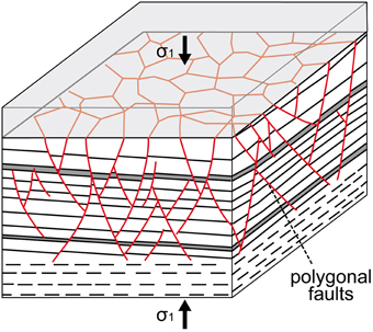
Figure 1. Conceptual sketch of polygonal faults in a sedimentary basin (modified from and inspired by Cartwright, 1994b; Cosgrove, 1998). Note that this particular type of normal faults forms polygonal meshes over horizontal cross-sections and are vertically restricted to particular stratigraphic intervals (or tiers) of sedimentary basins. Polygonal faults are thought as being diagenetic non-tectonic structures (Cartwright, 2011).
Polygonal faults, in particular, have been recognized in extensional basins from all over the world, within fine-grained rocks that range in lithology from smectitic claystone to almost pure chalk and span in age from late Jurassic to recent times (Cartwright and Dewhurst, 1998; Cartwright, 2011, 2014). Polygonal faults are identified through two decisive factors: (1) these faults are layer bound (i.e., intraformational or restricted to particular stratigraphic intervals or “tiers”) and (2) non-systematically oriented (i.e., polygonal), thus suggesting a non-tectonic origin (Figure 1).
Polygonal faults are thought to form during early burial and diagenesis as a consequence of heterogeneous lateral volume changes caused by or associated to laterally-heterogeneous mechanisms and parameters such as sediment compaction, fluid flow and pressure, gravitational loading, and chemically driven volumetric contraction or syneresis (Cartwright, 1994a, 2011; Cartwright and Lonergan, 1996; Cosgrove, 1998; Dewhurst et al., 1999; Watterson et al., 2000; Goulty, 2001, 2008; Gay et al., 2004; Dehandschutter et al., 2005; Goulty and Swarbrick, 2005; Victor and Moretti, 2006; Gay and Berndt, 2007; Davies et al., 2009; Meadows and Davies, 2009; Alves, 2010; Ireland et al., 2010; Davies and Ireland, 2011). Despite numerous studies, the origin of these faults remains still largely controversial.
The large number of studies on polygonal faults since their discovery (1990s) reflects the controversial origin as well as the importance in geofluid exploration and exploitation (Cartwright, 2011; Jackson et al., 2014). The non-tectonic, diagenetic origin of polygonal faults and, consequently, their geometrical randomness challenge the ability of geologists to predict fault and fracture patterns and their attributes particularly in fine-grained clayey or partly-clayey deposits that are often topseals for hydrocarbon accumulations (Cartwright et al., 2007) but also for subsurface artificial repositories of carbon dioxide (Arts et al., 2004) and nuclear wastes (Dehandschutter et al., 2005; Roche et al., 2012; Zaoui and Sekkal, 2015). The main cause for the uncertainty in the origin of polygonal faults is that they are well-known and documented in seismic images, but poorly known in outcrops. To the best of our knowledge, exposures of polygonal faults are only known or supposed in a few localities within Mesozoic chalk (United Kingdom, France, and Egypt; Hibsch et al., 2003; Tewksbury et al., 2014) and Paleogene claystone (Belgium; Dehandschutter et al., 2005). In particular, the only extensive exposures where polygonal faults have so far been observed and studied are located within chalk strata of the Cretaceous Khoman Formation near the Farafra Oasis in Egypt (Tewksbury et al., 2014).
In this study, we add three excellent fresh exposures to the presently limited database of polygonal fault outcrops. Our study exposures are the walls of a shooting range (Figure 2E) that has been recently carved within Albian-Turonian pelagic beds of fine-grained marly limestone with chert interlayers (Scaglia Bianca Fm.; Lotti, 1926). These exposures are located in the crestal (hinge) region of the late Messinian-early Pliocene Cingoli anticline (Figure 2), northern Apennines, Italy (Menichetti, 1991; Mazzoli et al., 2002; Petracchini et al., 2012, 2015; Antonellini et al., 2014). We acknowledge that the three studied exposures are sub-vertical across sub-horizontal or shallow-dipping alternating chert-limestone beds and no sub-horizontal exposures exist nearby. Hence, we could not verify whether the studied faults truly form map view polygonal patterns; however, our interpretation of these structures as polygonal faults is supported by compelling evidence that is presented below.
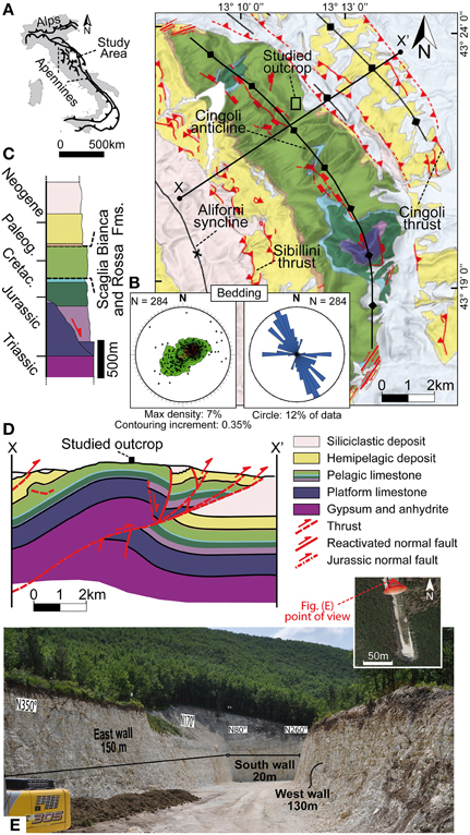
Figure 2. Geological setting of the study area (Cingoli anticline, northern Apennines, Italy). (A) Location of the study area in Italy. (B) Geological map of the Cingoli anticline area plotted over a 3D rendering of a digital elevation model (vertical exaggeration = 2). The Schmidt net (lower hemisphere) shows bedding poles and related contouring for the entire Cingoli anticline (attitude data are from Carta Geologica D'Italia, 2009). The rose diagram shows bedding strikes (same bedding data as in the adjacent Schmidt net). These data show that the anticline is more arcuate dome-like than cylindrical (see also Table A1). The Schmidt net and rose diagram were produced with the Open Plot software by Tavani et al. (2011). (C) Simplified stratigraphic column of the study area. The marly limestone with chert studied in this work (Scaglia Bianca Fm.) is indicated within the pelagic limestone sequence typical of northern Apennines. (D) Geological cross-section through the Cingoli anticline (modified from Mazzoli et al., 2002). See the X–X' track in Figure 1B. The study outcrop is located in the crestal (hinge) region of the Cingoli anticline and its location is indicated along the cross-section with a black rectangle. (E) Photograph of the studied exposures. Inset shows an aerial image from Google Maps displaying the study outcrop that is a trench-like shooting range recently carved into the Cingoli anticline hinge for a depth of about 15–20 m (latitude: 43° 22′ 29.81″N; longitude: 13° 11′ 38.85″E; elevation: 550 m).
Our main aim is to understand the nucleation and growth of the normal faults exposed in the Cingoli anticline hinge. The major novelty of this work is that the described faults are, in our interpretation, polygonal faults that were tectonically (syn-thrusting) rather than diagenetically driven. A further remarkable novelty is that these faults produced associated bed-parallel pressure solution on sub-horizontal carbonate beds that is an unprecedented or very rare case in syn-thrusting settings (e.g., Storti and Salvini, 2001; Tavani et al., 2008, 2012, 2015a; Amrouch et al., 2010a,b; Beaudoin et al., 2012).
Geological Setting
The exposures studied in this work are located in the hanging wall of the Cingoli thrust-related arcuate (salient-like) anticline (Italy) along the external front of the northern Apennines fold-thrust belt (Figure 2). The NE- to E-verging Cingoli anticline is an asymmetrical fold characterized by a NW-SE-oriented axis curving to approximately N-S in the southern part of the fold. Bedding dip domains measured all over the anticline (Carta Geologica D'Italia, 2009) show that, although the most frequent bedding dips are toward the north-east and south-west, the fold shape is arcuate domed with periclinal closures toward the north-west and the south and bedding dips toward most directions (i.e., multi-polarity; Figure 2B). As demonstrated by numerous previous studies, the map-view curvature (the curvature about a salient vertical axis) of anticlines can be one of the factors controlling the inner brittle deformation of anticlines (Dietrich, 1989; Price and Cosgrove, 1990; Tavani et al., 2015a,b). In map-view, the Cingoli anticline appears as one of the most arcuate anticlines of the northern Apennines. To make clear this point, we measured, on the Structural Model of Italy (Bigi et al., 1992), the horizontal radius of curvature for the 16 most arcuate anticlines in the central-northern Apennines. The Cingoli anticline results as having the third shortest radius among the 16 measured ones (Table A1).
The Cingoli anticline is confined by E-W-striking sub-vertical left-lateral faults in the north and by NNE-SSW-striking sub-vertical right-lateral faults in the south (Figure 2). In the east, the thrusts that drove the anticline formation are blind, buried beneath and sutured by Plio-Pleistocene marine and continental deposits, whereas, toward the west, the anticline laterally switches into the adjacent and parallel Aliforni syncline (Calamita et al., 1990; Menichetti, 1991; Deiana et al., 2002; Mazzoli et al., 2002).
The Cingoli anticline developed between late Messinian and early Pliocene times as part of the Neogene piggy-back thrust sequence of the northern Apennines belt. The Cingoli anticline involves the Meso-Cenozoic carbonate-dominated units typical of the Umbria-Marche (northern Apennines) sedimentary sequence, which formed in the tectonic-sedimentary environments described in the following (Santantonio, 1993, 1994; Marchegiani et al., 1999; Figure 2). During Hettangian-Sinemurian times, the area was dominated by a carbonate platform with the deposition of shallow-water limestones (Calcare Massiccio Fm.). The Calcare Massiccio is exposed in the Cingoli anticline core, where a NW-SE-oriented dip-slip normal fault is visible. This fault was active during early Jurassic times locally determining the formation of a post-platform pelagic basin (Marchegiani et al., 1999; Antonellini et al., 2014). Since Pliensbachian time onward, in fact, the large carbonate platform, which presently forms the middle-lower portion of the northern Apennines thrust sheets, (Figure 2) experienced extensional tectonics and was progressively sunk and largely covered by pelagic deposits of Jurassic to Eocene age. These pelagic deposits consist of fine-grained limestones with subordinate chert layers, marly-limestones, and marls, and include the Scaglia Bianca Fm. (late Albian-early Turonian time; Figure 2C), which is studied in this paper, and the overlying Scaglia Rossa Fm. (Turonian-Lutetian time), which is also shown in some figures of this paper. The lithological properties of the Scaglia Bianca and Scaglia Rossa Fms. are very similar (marly-limestones). Between late Eocene and early Messinian times, the area was characterized by the deposition of hemipelagic marls and marly limestones, which are interpreted as a sedimentary sequence deposited during the formation of the lithosphere flexure in the foreland and connected with the advancement of the Apennines thrust sheets (Deiana et al., 2002; Mazzoli et al., 2002). Since late Messinian time, the area was eventually involved into the Apennines orogenic deformation accompanied by the deposition of siliciclastic turbiditic sequences according to a progressive migration of the orogenic process from west to east (Calamita et al., 1990; Menichetti, 1991; Deiana et al., 2002; Mazzoli et al., 2002). The orogenic process affected the Cingoli area until the early Pliocene time, when marine clays (Argille Azzurre Fm.) sutured its NE-verging basal thrust. Contractional deformation along the northern Apennines belt is presently active 40–50 km to the north-east and north of the Cingoli anticline, namely in the northern Adriatic basin and Po plain regions (Scrocca et al., 2007; Carminati et al., 2010; Ventura and Di Giovambattista, 2013; Livio et al., 2014). For further stratigraphic and structural information on the Cingoli anticline area the reader is referred to the next sections and past studies (Carloni, 1960, 1964; Ciancetti and Nanni, 1989; Calamita et al., 1990; Menichetti, 1991; Marchegiani et al., 1999; Deiana et al., 2002; Mazzoli et al., 2002; Petracchini et al., 2012, 2015; Antonellini et al., 2014).
Workflow and Methods
Below, we present our previous and new results that are organized as follows: (1) we synthesize our results from previous structural studies (background) on the Cingoli anticline (Petracchini et al., 2012, 2015; Antonellini et al., 2014). These results are useful to understand the timing (relative to the Cingoli anticline formation) of the nucleation and growth of the normal faults analyzed in the following sections; (2) we present the field observations and data with particular focus on exposure images and on the attitude of faults, slickenlines, joints, and bedding. We also present a few X-ray diffractograms to better understand some observed pressure solution structures; (3) we focus on the fault terminations by presenting a photographic documentation and an analytical explanation for some field observations involving fault tip displacement and associated bed-parallel pressure solution; and (4) we present similarities and contrasts between the normal faults studied in the Cingoli anticline hinge and some polygonal normal faults buried in the North Sea basin (Cartwright and Lonergan, 1996; Cartwright, 2011). We focus, in particular, on fault pattern and abundance.
The methods adopted to complete this research are as follows: (1) field structural analysis; (2) X-ray diffraction; (3) analytical modeling of stress and deformation at fault tips; and (4) structure comparison with previous studies on presumably-similar normal fault populations.
(1) We conducted a standard field structural analysis drawing exposure sketches, taking oriented photographs, and collecting structural data such as fault displacements, structure attitudes, and crosscutting relationships. We processed these data doing geological line drawing of photographs and plotting the structural data on different types of diagrams: maximum displacement vs. dip-parallel fault length diagrams, Schmidt nets (structure attitude), Kalsbeek nets (density contour of linear structures such as poles to faults and beds), rose diagrams (structure strikes), and tangent lineation diagrams (attitude of fault surfaces and slip vectors).
(2) We conducted X-Ray diffraction (XRD) analyses on selected rocks using a Siemens D5000 device working in the Bragg Brentano (θ/2θ) geometry (CuKα radiation) at 40 kV and 45 mA. We carried out, in particular, semi-quantitative analyses of bulk samples. We analyzed randomly oriented whole-rock powders in the 3–65°2θ interval with a step size of 0.0025°2θ and a counting time of 1 s per step. To analyze and interpret the resulting diffractograms we used the XPowder12 software available online at http://www.xpowder.com/index.html.
(3) We conducted an analytical modeling of the fault tip local stresses and related deformations as predicted by linear elastic fracture mechanics (Fletcher and Pollard, 1981; Pollard and Segall, 1987) to explain some observed structures. To make results as comprehensible as possible, this procedure is better explained below together with the description of data.
(4) We conducted a comparison analysis between the faults observed in this study (Cingoli case) and those observed in a marine environment (North Sea case) to better understand similarities and contrasts between these two fault populations. The comparison is mainly based on rose diagrams of fault strikes and on outcrop and seismic reflection images. We recognized faults in these images using a simple technique of line drawing, and then computed the fault abundances using the inventory area method of Titley (1976). Also in this case, to make results as comprehensible as possible, this latter method is better explained below together with the description of data.
Background
The Scaglia Bianca and Rossa Fms. (beds of micritic marly limestone in places alternated with chert layers) in the Cingoli anticline and in most thrust sheets of the northern Apennines are usually characterized by multiple sets of contractional structures including bed-normal and bed-oblique pressure solution seams and reverse faults, which are variably oriented. In the Cingoli anticline backlimb, for instance, we observed seven main sets of pressure solution seams (Figures 3A–E) partly involved into later small-displacement reverse faults (Petracchini et al., 2012). These sets of seams nucleated in part during the layer-parallel-shortening phase (bed-normal seams) and in part during the later (syn-thrusting) folding phases (bed-oblique seams), which also led to late fault development. The finite deformation setting is schematically displayed in Figures 3D,E together with meso- and micro-scale instances of Scaglia Rossa Fm. beds affected by multiple sets of pressure solution seams and late faults (Figures 3A–C).
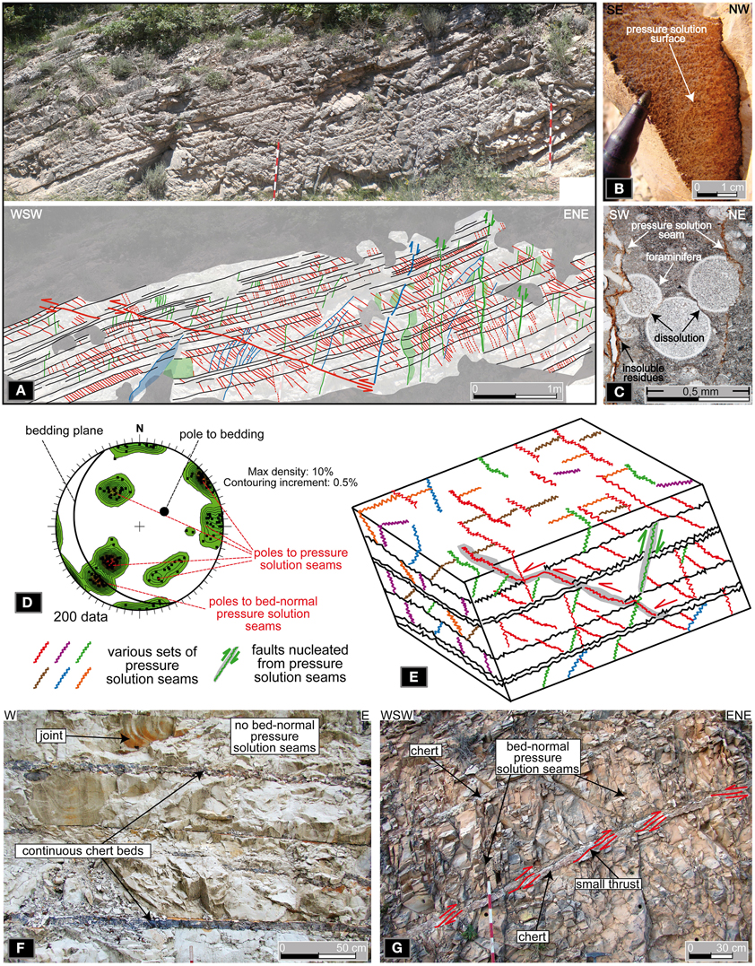
Figure 3. Background data (modified after Petracchini et al., 2012, 2015). (A) Photograph (above) and line drawing (below) of marly carbonate beds (Scaglia Rossa Fm.) dipping toward the south-west in the Cingoli anticline backlimb. The beds are affected by numerous sets of pressure solution seams including bed-normal ones developed during the layer-parallel-shortening (early thrusting) phase. (B) Photograph of a stylolitic surface of one of the bed-normal pressure solution seams shown in the previous photograph. (C) Micro-photograph displaying two of the bed-normal pressure solution seams shown in the previous photograph. Note the dissolution of fossils and other features across the seams. (D) Schmidt net (lower hemisphere, produced with the Open Plot software by Tavani et al., 2011) and (E) block diagram of the Cingoli anticline backlimb showing the attitude and conceptual distribution of the main sets of pressure solution seams. (F) Photograph of sub-horizontal carbonate and chert beds (Scaglia Bianca Fm.) from the Cingoli anticline. Due to the strengthening effect of the chert beds, these beds are not affected by contractional deformation such as bed-normal pressure solution seams and reverse faults. (G) Photograph of inclined carbonate and chert beds (Scaglia Rossa Fm.) from the Cingoli anticline. The chert beds are, in places, broken and affected by small thrusts. Correspondingly, in the carbonate beds, some bed-normal pressure solution seams developed.
An exception to the above-described deformation setting is represented by a few outcrops of Scaglia Bianca and Rossa Fms., where frequent continuous beds of chert alternate with carbonate beds (Figure 3F). In these outcrops, the chert beds strengthened the chert-carbonate composite sequence during the layer-parallel shortening phase (i.e., early thrusting phase) so that bed-normal pressure solution seams as well as reverse faults could not develop (Petracchini et al., 2015). In other words, the horizontal tectonic load (layer-parallel shortening phase) was mostly supported by the stiff and frequent chert layers and the strain of the whole chert-limestone composite remained in the elastic field, so that pressure solution seam development was prevented in the limestone beds (Figure 3F). On the contrary, where the same sequence was characterized by less frequent and thick beds of chert, the chert was, in places, broken and shortened by small thrusts and a few bed-normal pressure solution seams correspondingly developed in the carbonate beds (Figure 3G).
The exposures examined in the next sections are within the Scaglia Bianca Fm. and are characterized by alternating carbonate and chert beds. These beds are not affected by bed-normal and bed-oblique pressure solution seams and reverse faults. We therefore assume that these beds were horizontal and continuous (substantially undeformed) when the Cingoli area underwent layer-parallel-shortening (early thrusting phase) so that shortening (bed-normal pressure solution seams and reverse faults) was inhibited in these particular beds by the strengthening effect of the chert beds as shown in Figure 3F (Petracchini et al., 2015).
Results
Field Observations and X-ray Diffraction Data
The studied outcrop, which is located in the hinge of the Cingoli anticline (Figure 2), includes three main fresh exposures that are N170°–(East-Wall and West-Wall in Figure 2E) and N80°-oriented (South-Wall in Figure 2E). The exposures are all less than 20 m high and are ~150 m (East-Wall in Figure 2E), ~130 (West-Wall), and ~20 m (South-Wall) long. The exposed rocks belong to the Scaglia Bianca Fm. (meaning white chip). This formation, in general, consists of bedded pelagic micritic limestone of late Albian-early Turonian age (Lotti, 1926; Arthur and Fischer, 1977; Coccioni and Galeotti, 2003). In some sections, the carbonate beds of the Scaglia Bianca Fm. are alternated with frequent beds of dark chert between 1 and 15 cm thick (e.g., Petracchini et al., 2015). The limestone is usually marly with variable clay content (1–5%). The Scaglia Bianca Fm. is known in outcrops from all northern Apennines (Umbria, Marche, and Lazio regions), but also in some localities of the southern Apennines and related foreland (Puglia region). The thickness of the Scaglia Bianca Fm. is between 50 and 70 m, whereas the thickness of the carbonate beds, as marked by bedding-parallel stylolites, is between 10 and 110 cm. As the Cingoli anticline has not been over thrust by tectonic sheets, based on simple stratigraphic considerations (Figure 2C), we deduce that the studied exposures of Scaglia Bianca Fm. have been exhumed from a depth of about 800 m (Bally et al., 1986).
The exposures are characterized by sub-horizontal to shallow-dipping beds of micritic marly limestone with chert interlayers (Figure 2) and are affected by normal faults and joints. The faults are closely spaced (between c. 0.5 and 2–3 m along horizontal lines) and characterized by vertical offsets that, with the exception of a few late stage faults, generally vary between about 1 and 60 cm. Slickolites along fault surfaces are very common and indicate a downdip displacement for all faults with a pitch value of about 90° for all measured slickolites, which are characterized by sub-vertical columns. Abrasion striae and striated calcite fibers are also present on some fault surfaces. We measured the attitude of bedding, joints, faults, and related slip lineations (slickenlines) and all results are shown in Figure 4.
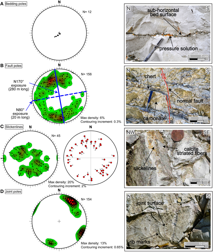
Figure 4. Structure attitude data (left) plotted on Schmidt nets (lower hemisphere; produced with the Open Plot software by Tavani et al., 2011) and related photographic examples (right) from the study outcrop. (A) Poles to bedding (left) and example of stylolitic horizontal bedding surface (right). (B) Poles to faults and related density contour lines (left) with an example of fault affecting the carbonate and chert beds (right). (C) Fault slickenlines and related density contour lines (left plot) with an example of fault surface affected by both slickolites and striated calcite fibers (photograph). Fault slickenlines and related fault surfaces are also shown in the tangent lineation diagram (right plot; e.g., Hoeppener, 1955), where the arrows indicate the slip of the fault hangingwalls with respect to the related fault footwalls. In the diagram, the slip pattern is centripetal due to the poorly-systematic orientation of faults, over which the normal displacement is nearly-pure dip-slip. This tangent lineation diagram was produced with the Orient software by Vollmer (1995). (D) Poles to joints and related density contour lines (left) with an example of joint surface affected by typical rib marks (right).
Figure 4A shows that the study outcrop consists of sub-horizontal beds as is typical for several anticline hinge domains. Figure 4B shows that the studied faults strike in most directions with an average dip around 60° (i.e., average dip value of 156 faults) and dip plunge toward all directions except west-southwest. Figure 4B shows also the strike of the vertical exposure walls (Figure 2). Figure 4C shows that the slip lineations (slickenlines in left diagram of Figure 4C) measured over the studied fault surfaces plunge toward all directions except west-southwest. The mean pitch angle (deduced from the attitude of each measured slickenline on each fault surface; Figures 4B,C) for the measured slickenlines is about 87° (average value of 45 data) showing that the faults are dip-slip (normal as inferred from the downdip offsets in Figures 5–7). The tangent lineation diagram (right plot in Figure 4C; e.g., Hoeppener, 1955), in particular, shows the slip of the fault hangingwalls with respect to the related fault footwalls. The slip pattern is centripetal due to the poorly-systematic orientation of faults, over which the normal displacement is nearly-pure dip-slip. Figure 4D shows that the joints observed in the studied exposures are sub-vertical and grouped in two main sets based on their strike: a major set striking WNW-ESE and a minor set striking perpendicularly to the major one.
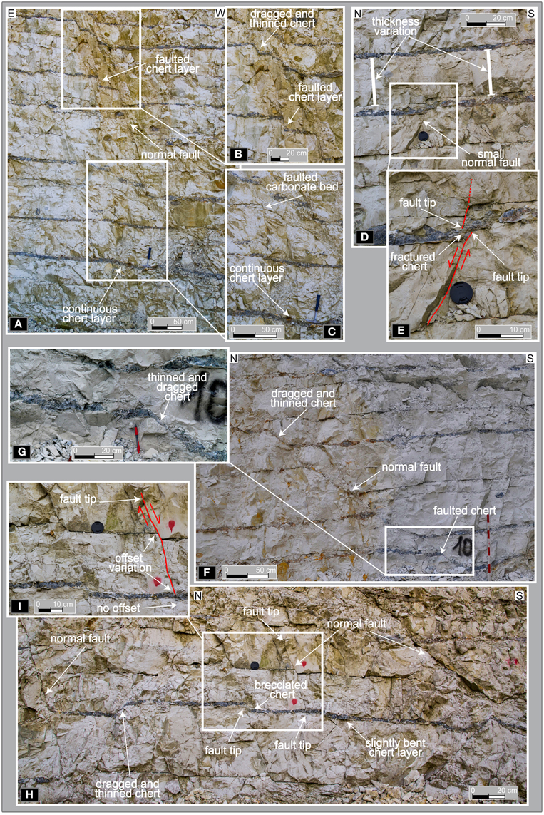
Figure 5. Exposure photographs (Scaglia Bianca Fm.). (A) Normal faults across alternate carbonate-chert beds. (B,C) Enlargements from the previous photograph. Note that the faults cut through the carbonate beds, but generally do not offset the chert layers, which are bent, dragged, and thinned over the fault surface. The fault offset fades away moving downdip where a chert layer is slightly bent. (D) Normal fault across carbonate-chert beds. Note the lateral variation of carbonate bed thickness. (E) Enlargement from the previous photograph. Note the small fault displacement that fades away updip and the fault step corresponding to the intersection with a chert layer that is slightly bent. (F) Intermediate-angle normal fault across carbonate-chert beds. (G) Enlargement from the previous photograph. Note the thinning of the chert layer along the fault surface. (H) Normal faults across carbonate-chert beds. (I) Enlargement from the previous photograph. Note the faults abutting against the chert layers and the offset variation along the faults.
Except for a few faults, which cut across the entire exposures, all faults are short in downdip length, usually between 0.1 and 3–4 m (Figures 5, 6). The main feature of almost all faults is that they cut entirely or partly the carbonate beds (some of the faults die indeed within the carbonate beds), but usually abut against the chert layers (Figures 5E,G, 6B,D,G,I,J). In particular, the chert layers almost always appear as bent and dragged downdip along the fault surfaces without being cut by the faults themselves (Figures 5–7) so that the faults step downdip from one segment to the next in proximity of a chert layer (Figures 5E, 6B,H–J). In other words, there is a step of the fault segments (i.e., accommodation zone) in proximity to the chert beds, along which deformation is normally accommodated by bending and stretching rather than faulting. The portions of chert beds that are located more than 5–10 cm away from the faults are undeformed or poorly fractured (Figures 5E,I), whereas the portions located near the faults and involved in the deformation (i.e., the chert beds bent and dragged along the fault surfaces) are usually continuous along the entire fault dragging length, but are strongly thinned and tapered (i.e., a sort of brittle smearing or shattering of the chert along fault surfaces; Figures 5G, 6B,D,H). The along-fault bending and dragging of the chert beds appear to be accomplished through brittle processes rather than ductile ones (Figure 6). In particular, the bent and thinned section of the chert beds is intensely fractured and finely brecciated (i.e., shattered) with brittle deformations well visible at the naked eye (Figures 7C–E). In one case, we observed the evidence for micro-domino faulting affecting the thinned portion of the chert beds (Figure 6G). Only in a few instances, we observed that the chert beds were so stretched and tapered along the fault surfaces to lose their lateral (along-bedding) physical continuity and generate an offset of about 20–30 cm at the most (Figures 6A,H). Where the chert bed is bent and brecciated along the fault surfaces, this breccia is often associated with carbonate bed fragments (Figure 7D), hence indicating post-lithification fault-related brittle deformation (brecciation) for both the carbonate and the chert beds.
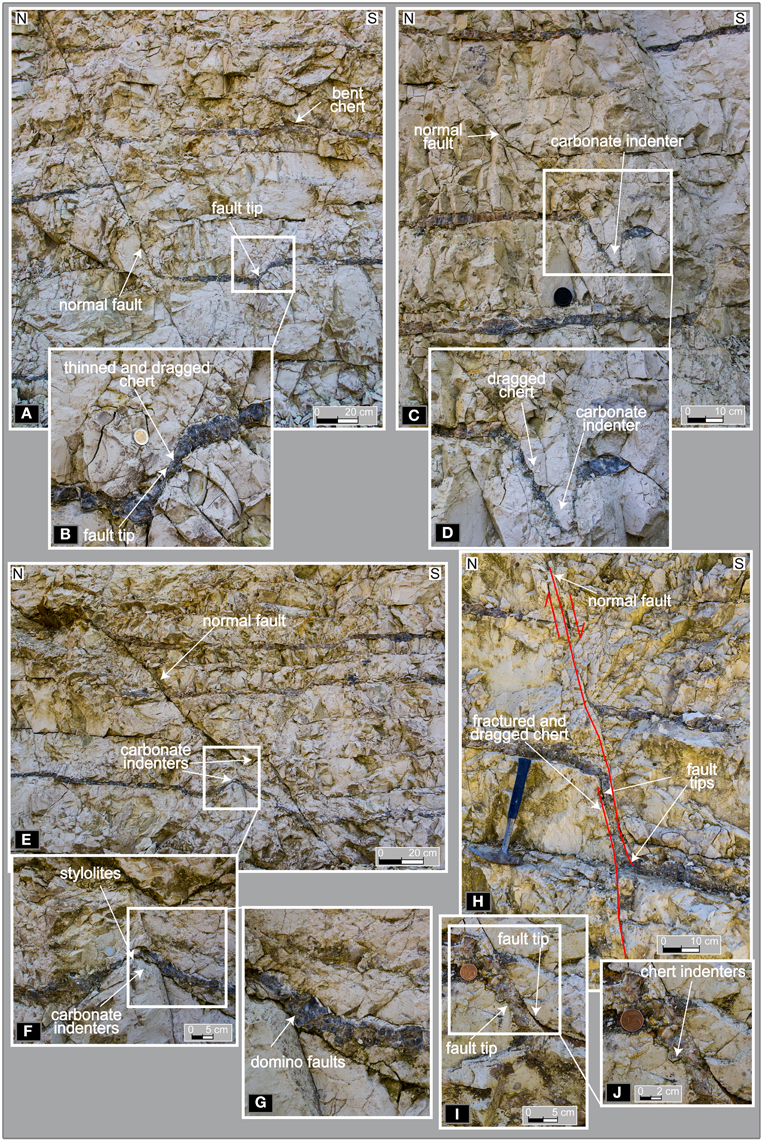
Figure 6. Exposure photographs (Scaglia Bianca Fm.). (A) Normal faults across alternate carbonate-chert beds. (B) Enlargement from the previous photograph. Note that the faults abut against the chert layer that is dragged downdip along the fault surface. (C) Normal faults across alternate carbonate-chert beds. (D) Enlargement from the previous photograph. (E) Normal faults across carbonate-chert beds. (F) Enlargement from the previous photograph. Note the stylolitic profile of the chert-carbonate lower interface. (G) Enlargement from the previous photograph. Note the small domino faults and other brittle deformation affecting the chert layer. (H) Normal faults across alternate carbonate-chert beds. (I) Close-up photograph from the studied outcrop. Note that the faults terminate against the chert layer that is bent and dragged consistently with the normal fault offset. (J) Enlargement from the previous photograph. Note that the downward chert indenters into the lower carbonate bed are not vertical, but seemingly rotated about a horizontal axis by about 45° consistently with the normal fault offset.
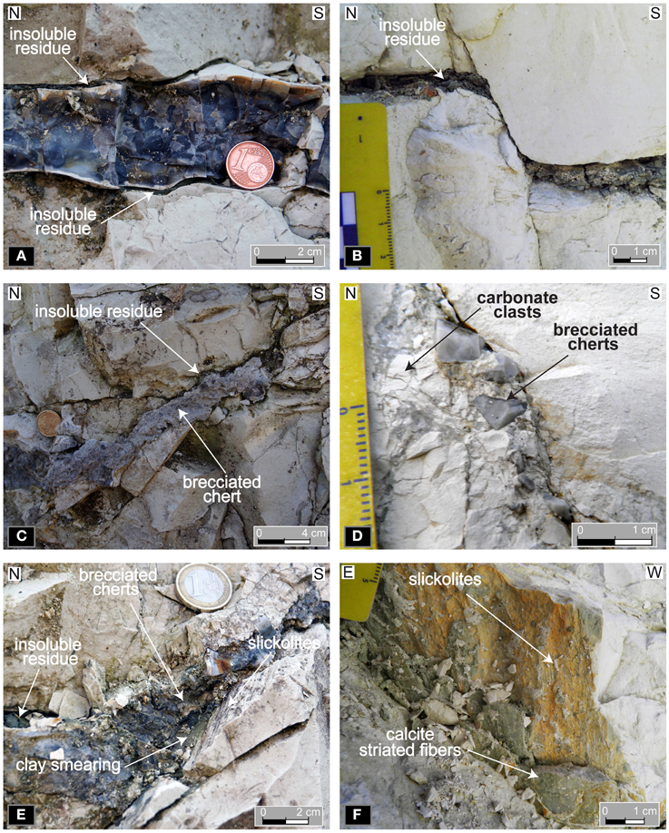
Figure 7. Exposure photographs (Scaglia Bianca Fm.). (A) Thin layers of clayey insoluble residue (from pressure solution) at the interface between carbonate and chert beds. (B) Thick layer of clayey insoluble residue (from pressure solution) parallel to bedding and smeared along a fault surface. (C) Thin layers of clayey insoluble residue (from pressure solution) at the interface between carbonate and chert beds. (D) Breccia along a fault surface. Note that the breccia includes both chert and carbonate clasts. (E) Brecciated chert along a fault surface in carbonate rock. The surface is characterized by downdip slickolite lineations and by greenish clayey insoluble residue partly smeared along the surface itself. (F) Slickolite lineations and calcite striated fibers along a normal fault surface.
Evidence of bed-parallel pressure solution is frequent in the carbonate beds (Figures 7A–C). Bed-parallel stylolites occur as discrete and well-visible planar structures accompanied by thin layers (less than c. 1.5 cm thick) of greenish, clayey, possibly-residual material (Figure 4A). These pressure solution structures occur particularly along the interface between carbonate and chert beds, but also far away from these interfaces. Along the carbonate-chert interfaces, the undulations and asperities typical of the chert layers appear as vertical dissolution indenters within the adjacent carbonate beds. In several cases, we observed that, in proximity to a normal fault, the chert indenters into the adjacent carbonate bed are not sub-vertical as is their original attitude, but appear rotated about a horizontal axis by circa 45° (e.g., Figure 6J). This rotation is consistent with the downdip bending of the chert layer along the normal fault surface. As mentioned above, both the bed-parallel pressure solution surfaces and the fault surfaces with slickolites are characterized by thin (between 0.1 and 1.5 cm) layers of greenish clayey material (Figures 7A–C,E). To understand whether this material is the residual product of carbonate pressure solution processes, we analyzed a set of samples through X-ray diffraction (XRD) to determine the mineralogical composition. Figure 8 shows the XRD results from samples of greenish clayey thin layers observed along some carbonate-chert interfaces and along some fault surfaces (Figures 8A,B, respectively). For comparison, we also analyzed the non-carbonate residual material obtained after total dissolution of a carbonate sample (Scaglia Bianca Fm.) attacked with an acidic solution (water-diluted HCl; Figure 8C). XRD results for the three different samples are characterized by similar diffractogram patterns and peaks indicating the presence of clays (Illite and Montmorillonite) and two other silicate minerals (namely Quartz and K-feldspar) in all samples (Figure 8).
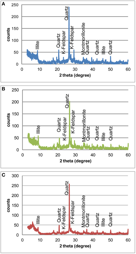
Figure 8. Results (diffractograms) from X-ray diffraction (XRD) analyses. (A) Diffractogram from the analysis on clayey residual material from pressure solution seams occurring at the carbonate-chert interface (e.g., Figure 7B). (B) Diffractogram from the analysis on clayey residual material from fault surfaces with slickolites (e.g., Figure 7E). (C) Diffractogram from the analysis on clayey residual material obtained after laboratory total dissolution of a carbonate sample (Scaglia Bianca Fm.) in an acidic solution (water-diluted HCl).
To understand the growth of the studied faults, we measured the maximum slip-parallel displacement (D) and dip-parallel length (L) (e.g., Watterson, 1986; Dawers et al., 1993; Cartwright et al., 1995; Dawers and Anders, 1995; Fossen and Hesthammer, 1997; Kim and Sanderson, 2005; Soliva and Benedicto, 2005; Soliva et al., 2005; Gudmundsson et al., 2010, 2013; Gudmundsson, 2011; Roche et al., 2012) of a population of 30 faults exposed in the study outcrop (Figure 9). In Figure 9, the data population is characterized by a linear trend (with large scattering) with D rapidly increasing with increasing L. The average L and D values are 72.5 and 11.8 cm, respectively, indicating that the fault displacement is averagely 16.3% of the fault length.
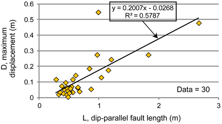
Figure 9. Fault maximum displacement (D) vs. dip-parallel length (L) diagrams for the Cingoli faults. The black line is the linear best fit.
Pressure Solution at Fault Terminations
To better understand the growth of the studied normal faults, in this sub-section, we focus on the deformation (pressure solution, in particular) observed at many fault terminations (Figure 10). To a first approximation, we explain part of this deformation in terms of the fault tip local stresses as predicted by linear elastic fracture mechanics (Figure 11; Fletcher and Pollard, 1981; Pollard and Segall, 1987).
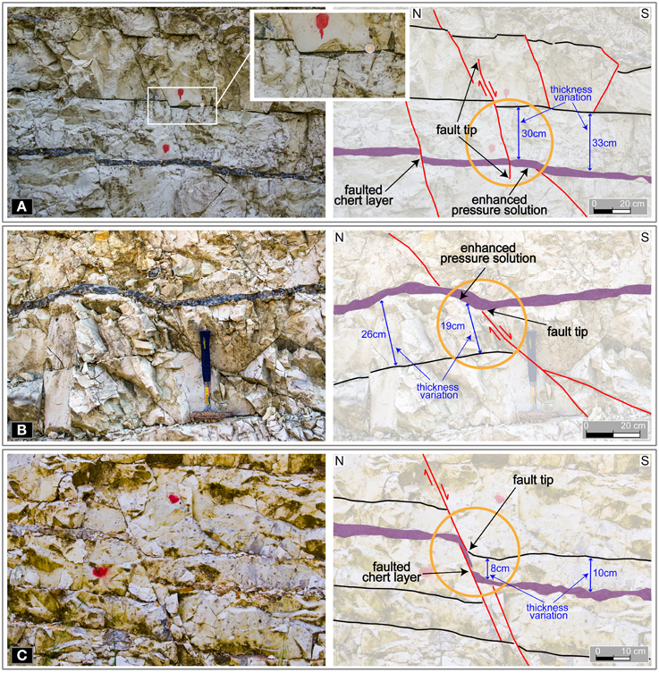
Figure 10. (A–C) Photographs (left) and related line drawing (right) of three instances of fault terminations from the study outcrop in the Cingoli anticline hinge. In all instances, note the tapering (accomplished through bed-parallel pressure solution) of carbonate beds in approaching the compressional quadrant of normal fault tips (see the fault compressional quadrants in Figure 11A). Inset in (A) shows a close-up view of a bed-parallel pressure solution seams with a thick layer of greenish clayey residual material.
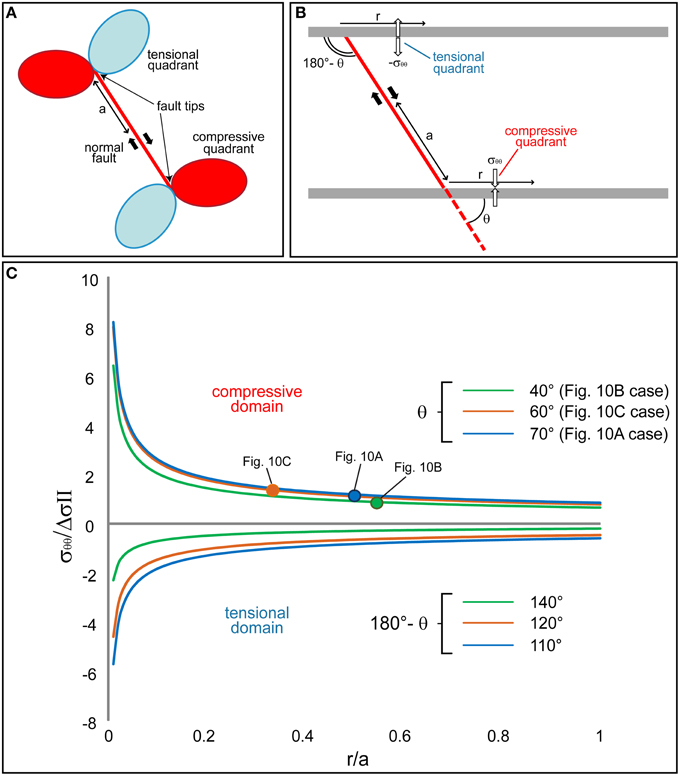
Figure 11. (A) Perturbed stress quadrants (two compressional and two tensional) near the tips of a propagating normal fault (Pollard and Segall, 1987). (B) The fault is approximated with a mode II fracture (i.e., where slip and shear fracture propagation are parallel) in a cylindrical coordinates (r, θ) reference system to solve for the circumferential stress in proximity to the fault tip. r is the radial distance from the fault tip of any point on a geological feature of interest, θ the angle from the fault plane, and a the half length of the fault. The circumferential stress (σθθ) will act on the pre-existing discontinuity (stylolite or bedding plane) near the fault tip in a way to affect the amount of pressure solution (on the discontinuity itself). (C) This diagram shows the circumferential stress normalized by the driving stress (σθθ∕ΔσII) as a function of r/a in the compressional (ordinate positive values) and tensional (ordinate negative values) quadrants. θ values larger than 90° represent the circumferential stress on the sub-horizontal discontinuities in the tensional quadrant, whereas θ values smaller than 90° represent the circumferential stress on the sub-horizontal discontinuities in the compressional quadrant. Also the r/a values beyond which there is no more tapering of the strata in Figure 10 are reported as colored dots on the plot. Along the horizontal axis, beyond these dots, there is no significant effect of the fault tip stress concentrations on pressure solution on the sub-horizontal discontinuities.
Fault slip, also at its incipient stage, generates a stress concentration at fault terminations that, for some components, may exceed in magnitude the driving stress on the fault itself. The result of such stress concentrations is that four perturbed stress quadrants arise at the two sides of each fault terminations (Figure 11A): two compressional quadrants where the mean local stress is larger than the remote one and two opposite tensile quadrants where the mean local stress is smaller than the remote one. Pressure solution seams and extensional fractures can develop in the compressional and tensile quadrants, respectively, as tail structures departing from the fault tip area and forming an angle of ~70° with the fault surface (Erdogan and Sih, 1963; Cotterell and Rice, 1980; Pollard and Segall, 1987; Cruikshank et al., 1991; Cruikshank and Aydin, 1994; Homberg et al., 1997; Willemse and Pollard, 1998). In this sub-section, we further explore the possibility that these fault tip processes influence (enhance pressure solution, in particular) the local stresses on discontinuities already existing in the rock before the nucleation of the faults. These discontinuities (i.e., bed-parallel stylolites, chert-limestone interfaces, etc.), once influenced by the stress perturbations at the fault tips, might develop with different amount of opening or closing (pressure solution) displacement according to their distance and orientation from the fault tip and the kind of quadrants they fall into (Figures 11A,B).
Figure 10 shows three examples of normal fault terminations from the studied exposures. Many other instances similar to those of Figure 10 occur in the study outcrop. In Figure 10, areas of main interest are encircled with an orange ring. Figure 10A, in particular, shows a fault downdip tip where the chert is almost undeformed (only some slight shattering toward the south). It is interesting to note that the carbonate bed is tapered (by about 3 cm) approaching the fault (in the compressional quadrant), close to which the bed-parallel pressure solution seams are particularly evident and accompanied by a thick layer of greenish clayey residue (see inset in Figure 10A). This fault is 72 cm long, and 70° dipping, and characterized by a maximum displacement of 4 cm.
An instance similar to Figure 10A is shown in Figure 10B, where a fault updip termination is characterized, in the compressional quadrant, by a marked tapering (by about 5–8 cm) of the carbonate bed accompanied by obvious bed-parallel pressure solution seams and by an incipient shattering and bending of the chert bed. This fault is 110 cm long, and 40° dipping, and characterized by a maximum displacement of 15 cm.
Figure 10C shows an instance characterized by bending of the chert beds at the fault tip for a length of a few centimeters. Obvious tapering (by a few centimeters) of the carbonate bed in the fault compressional quadrant is also visible. This tapering is accompanied by a marked deformation of the carbonate beds accomplished through pressure solution as evidenced by a bed-parallel clayey residual layer. The fault observed in Figure 10C is 89 cm long, 60° dipping, and characterized by a maximum displacement of 17 cm.
The crosscutting relationships between faults and pressure solution seams are of two main types: (1) the pressure solution seams emanate from the fault tips (e.g., tail-like structures in Figures 6H, 10C) or (2) they are displaced by the faults themselves (e.g., Figures 5D, 10A).
Following Pollard and Segall (1987; Figure 11A), we analytically explore the stress distribution at the tip of a propagating normal fault in a way to explain the observations made on the exposures shown in Figure 10. In Figure 11C, in particular, we use the physical data (i.e., fault length, radial distance from the fault tip, and angle between pressure solution seams and fault plane) collected in the three cases of Figure 10 to infer the influence of the tip stress concentrations along tail structures as a function of fault distance for different fault-tail angles. We approximate the propagating normal fault as a mode II fracture (i.e., where slip and shear fracture propagation are parallel) and use a cylindrical coordinate system (r, θ) to solve for the circumferential stress in proximity to the fault tip (see Figure 11B for the reference system). In our assumption, the circumferential stress will act on the pre-existing discontinuity (stylolite or bedding plane) near the fault tip in a way to affect the amount of pressure solution (on the discontinuity itself). According to Lawn and Wilshaw (1975, p. 54) the circumferential stress (σθθ) near the fault tip can be expressed as:
where ΔσII is the driving stress on the fault, a is the half length of the fault, r is the radial distance of any point on a geological structure of interest from the fault tip, and θ is the angle from the fault plane.
Given that the discontinuities (stylolites and bedding interfaces) observed in the Scaglia Bianca Fm. are subhorizontal and that the normal faults have a dip angle generally between 40 and 70° (average fault dip = 56°; Figure 4B), we compute the circumferential stresses in the compressional quadrant with θ ranging from 40 to 70° and in the tensional quadrants with θ ranging from 110 to 140° (180° - θ). The results are presented in Figure 11C, where the curves represent the three situations observed in Figure 10. Note that, in these three situations, θ is 40, 60, and 70°, respectively.
Figure 11C, in particular, shows the ratio between the circumferential and driving stresses (σθθ∕△σII) as a function of r/a in the compressional (positive values) and tensional (negative values) quadrants. The r/a values beyond which there is no more tapering of the strata in Figure 10 are reported as colored dots on the plot of Figure 11C. Hence, we assume that the strata tapering is induced by the fault tip stress concentrations and infer that for r/a values greater than these dots there is no significant effect of the stress concentrations on pressure solution along the sub-horizontal discontinuities.
In Figure 11C, the σθθ∕△σII ratio is high (>3) for r/a < 0.1. In the area next to the fault tips, in effect, we expect to have the largest influence on pressure solution in terms of an increase, within the compressional quadrants, and hence of a diminishing in bed thickness. We expect, in contrast, a decrease of pressure solution within the tensional quadrant and a corresponding null or reduced diminishing in bed thickness. This latter effect is related to pressure unloading due to the component of the circumferential stress working against the uniform lithostatic load of the sedimentary sequence. According to this model and next to the fault tips, we would expect areas where the bedding thickness decreases (enhanced pressure solution; Figure 10) and areas where it does not decrease (reduced or annulled pressure solution) or even apparently increases with respect to the bedding thickness far away from the fault. The apparent increase of bed thickness can occur in the tensional quadrants (stress relief impeding pressure solution) provided that outside the quadrants themselves the carbonate bed undergoes shrinkage due to overburden-related pressure solution. The final impression is thus that bed thickness is increased in the tensional quadrants close to fault tips, whereas this is merely the effect of relative shrinkage of bed thickness in approaching a fault tip. Evidently, the above-depicted fault tip processes are modulated by the position of the slipping fault patch with respect to the sub-horizontal discontinuities (e.g., stylolites) that might fall into the compressional or extensional quadrants generated by the propagating fault (Figure 11C).
Similarities and Contrasts with Polygonal Faults Buried in Marine Basins
Following the hypothesis advanced in the introductory section that the studied normal faults could be polygonal (see also Figures 4B,C), in this sub-section, we present similarities and contrasts between the studied faults (Cingoli faults; Figure 12A) and a set of polygonal normal faults buried in the North Sea basin (North Sea faults) and imaged through seismic reflection data (Figure 12C; Cartwright, 2011). The cross-sectional comparison between the Cingoli and North Sea faults (Figure 12) shows a striking geometrical similitude between the two populations despite the huge difference in scales. The scale of the outcrop image (Cingoli) is, in effect, about 400 times larger than the scale of the seismic image (North Sea basin). Faults, in both images, are characterized by similar geometrical and displacement patterns, which are distributed into horst-and-graben-like structures. In both cases, the faults are restricted either upwardly, downwardly, or both (i.e., intraformational), and are characterized by laterally-variable offsets. The Cingoli faults have an average 56° dip (Figure 4B) toward both ends of the cross-sectional view (opposite dip-polarities), similarly to the North Sea faults that have an average 62° dip (i.e., average apparent dip from 32 faults in the depth-converted seismic reflection image of Figure 12C) with opposite dip-polarities as well. In both cases, faults reciprocally crosscut or abut indicating a contemporaneous growth.
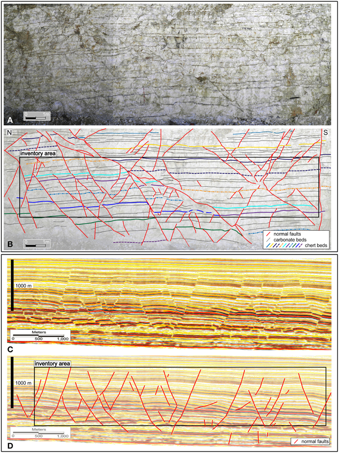
Figure 12. (A) Cross-sectional view (photomosaic) of a portion of the East-Wall (Cingoli anticline; Figure 2E). Note the normal faults and related displacements. (B) Line drawing of the previous photomosaic rectified for photographic distortions. The black rectangle is the inventory area used to calculate the fault abundance (see text). (C) Seismic reflection profile from the North Sea basin (modified from Cartwright, 2011). The profile was depth-converted using a P-wave velocity of 3000 m/s that is typical of chalk (e.g., Vejbæk et al., 2005), which forms most of this cross-section. (D) Line drawing of the previous seismic profile. The black rectangle is the inventory area used to calculate the fault abundance (see text). The profile shows the characteristic structural style of a simple tier, with approximately equal numbers of mainly planar to gently listric normal faults dipping in apparent conjugate directions. The upper tips are located within two-three reflections of a common boundary; similarly for the lower tips. Note the similar structural pattern in (B,D) despite the large difference in scales.
To evaluate if the two analyzed fault populations are characterized by a similar abundance per unit area, we measured this parameter (i.e., fault abundance) using the inventory area method (Titley, 1976; Wheeler and Dixon, 1980; Pohn, 1981; Davis and Reynolds, 1996; Billi et al., 2007; Rossetti et al., 2007). In this method, the fault abundance (Af) is defined as the total cross-sectional length of all faults (Ltot) falling within a significant (i.e., for the fault abundance) inventory area (IA) divided by the area itself (Af = Ltot/IA). In Figures 12B,D, we drew the two inventory areas (i.e., two rectangles with the same side proportion) encompassing most faults in each image and measured Ltot for each area. The resulting Af is 1.5 m−1 for the Cingoli case and 2.6 × 10⁻³ m−1 for the North Sea case. In other words, Af for the Cingoli case is about 570 times larger than Af for the North Sea case. It follows that the Af difference (570 times larger in the Cingoli case) is similar to the image scale difference (400 times larger in the Cingoli case).
Eventually, in Figure 13, we compare the strike pattern of the Cingoli fault population against the pattern of a population of polygonal normal faults from the North Sea analyzed by Cartwright and Lonergan (1996). The polygonal faults of the North Sea are unsystematic (polygonal) with three main peaks along the N15°, N60°, and N150° directions (Figure 13C). The faults from the Cingoli anticline are apparently less unsystematic (Figure 13A), but the strike pattern is probably biased by the occurrence of only two exposure orientations and by 280 m of exposure along the N170° direction against only 20 m of exposure along the N80° direction. To verify this possible bias, we selected 20 m from the N170°-trending exposures (East wall in Figure 2E) and plotted the related fault strikes in a rose diagram (Figure 13B) together with the fault strikes measured along the available 20 m from the N80°-trending exposure (South wall in Figure 2E). The resulting rose diagram shows a fault strike population similar to that of the North Sea (compare Figure 13B and Figure 13C) and confirms the likelihood of a sampling bias on the fault strikes induced by the available exposure orientations in the Cingoli anticline. Such a bias is not likely, in contrast, in the case of the North Sea (Figure 13C), where the fault strikes are measured over horizontal seismic data slices (Cartwright and Lonergan, 1996).
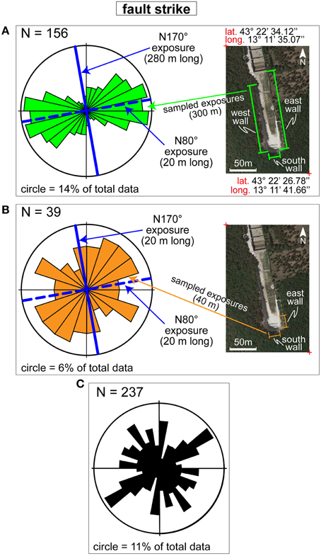
Figure 13. Rose diagrams for comparison of normal fault orientation from the Cingoli anticline hinge (data from this work) and the North Sea (data from Cartwright and Lonergan, 1996). (A) Complete set of data from the Cingoli anticline (same data as in Figure 4B). (B) Selected data from the Cingoli anticline. These faults are from 20 m exposure along the N80° direction (South wall in Figure 2E) and 20 m exposure along the N170° direction (East wall in Figure 2E). Diagrams in (A,B) were produced with the Open Plot software by Tavani et al. (2011). (C) Polygonal normal fault strike from the North Sea.
Discussion
Are the Cingoli Faults Polygonal?
The first issue that we discuss is whether the faults studied in the hinge of the Cingoli anticline can be geometrically and kinematically (regardless of their origin and development mechanisms) considered polygonal faults as these latter structures are depicted and defined in numerous previous articles (e.g., Cartwright, 2011, 2014; Tewksbury et al., 2014 and references therein). A series of evidence support the hypothesis that the Cingoli faults are polygonal:
(1) first of all, the Cingoli faults are normal (Figure 4) as are all polygonal faults hitherto documented (Cartwright, 2011 and references therein);
(2) the cross-sectional pattern of the Cingoli faults and that of polygonal faults buried in the North Sea basin and elsewhere in marine settings (Cartwright, 2011 and references therein) is very similar despite a remarkably different scale of observation (Figure 12);
(3) the Cingoli faults developed in subhorizontal marly carbonate strata as happens for the majority of polygonal faults previously described in the literature (in smectitic claystone to almost pure chalk according to Cartwright, 2011 and references therein);
(4) although we could not find horizontal exposures where verifying the polygonal pattern of the Cingoli faults (e.g., Tewksbury et al., 2014), attitude of these faults is poorly-systematic with fault dips and slickenlines plunging toward most directions (Figure 4), thus suggesting a map-view polygonal fault pattern. Fault strikes, in particular, are characterized by a main NE-SW trend (Figure 13A), but this result is at least in part biased by structure sampling chiefly along the two longest N170°-trending exposures (Figure 2E). The sampling bias is markedly reduced in the rose diagram of Figure 13B, where the fault strikes are in all directions similarly to the polygonal normal faults of the North Sea basin (Figure 13C);
(5) the studied faults, in places, crosscut or abut one another (compare Figures 12A,B with Figures 12C,D), thus suggesting a substantial contemporaneous growth that is another evidence supporting the formulated hypothesis (i.e., the Cingoli faults are polygonal);
(6) as is typical of all polygonal faults previously described in the literature (Cartwright, 2011 and references therein), also the Cingoli faults are short in dip-parallel direction and are restricted to a particular stratigraphic interval or “tier” (i.e., intraformational). These faults are, in effect, observed only in the study outcrop (Figure 12A) within a few beds of the Scaglia Bianca Fm. (Petracchini et al., 2012, 2015; Antonellini et al., 2014);
(7) the Cingoli faults accommodate differential vertical offsets occurring in laterally-adjacent compartments (Figure 12A) as happens for the majority of polygonal faults previously described in the literature (Cartwright, 2011 and references therein).
(8) the fault abundance appears to be significantly different when measured on the Cingoli exposures and on the North Sea seismic images, but this difference seems to be chiefly or solely controlled by the difference of observation scales (Figure 12B vs. Figure 12D).
The above-reported evidence suggests that the Cingoli faults can be geometrically and kinematically classified as polygonal normal faults.
Fault Timing
The second issue that we discuss is the timing of the Cingoli polygonal faults with respect to the development of the Cingoli thrust-related anticline. A few evidences allow us to constrain this relative timing:
(1) The first evidence includes the occurrence of some cataclastic breccias (with carbonate and chert clasts) along the fault surfaces together with fault surface striations and shattering (brittle deformation) of the chert beds in the fault proximity (Figures 4C, 6I, 7C–F). All this evidence suggests that the Cingoli polygonal faults developed in post-lithification times and not during early burial when rocks were soft and poorly diagenized as assumed for many previously-studied polygonal faults (Cartwright, 2011, and references therein).
(2) We observed the type of faults analyzed in this manuscript (i.e., poorly-systematic, small-displacement, normal faults restricted to particular stratigraphic tiers) only in the study outcrop. No similar faults occur in other localities of the Cingoli anticline (Petracchini et al., 2012, 2015; Antonellini et al., 2014). Moreover, this type of faults has not hitherto been reported and documented in the Scaglia Bianca Fm. and adjacent pelagic-to-hemipelagic carbonate formations from all over the entire northern Apennines. This evidence suggests that the Cingoli polygonal faults are probably not related to soft sediment syn-diagenetic deformation, but must be correlated to their specific structural position, i.e., the Cingoli anticline hinge, and hence to the anticline development.
(3) The Cingoli polygonal faults generated several discontinuities and weakness zones through the carbonate and chert beds of the Scaglia Bianca Fm (Figure 12A). We presume that, if these discontinuities were generated prior to the anticline development (pre-thrusting stage), these same discontinuities would have been inverted or deformed at least during the layer-parallel shortening stage (early thrusting and folding stage). We deduce, therefore, that the Cingoli polygonal faults can not be pre-thrusting (pre-Cingoli anticline) and must be post-layer-parallel shortening (post-early thrusting).
(4) The Cingoli normal faults are not likely post-thrusting as post-orogenic (Plio-Pleistocene) extensional tectonics is not known for this part of the Apennines (Chiarabba et al., 2005; Montone et al., 2012). Moreover, a post-thrusting extensional tectonics would have generated normal faulting across the entire Cingoli anticline (where normal faulting is substantially absent) and not only in its hinge area.
From the above-discussed evidence, we deduce that the Cingoli polygonal faults can be neither pre- nor post-thrusting and must be therefore syn-thrusting (i.e., syn-folding).
Fault Nucleation and Growth
The last issue that we discuss is the fault nucleation and growth. As previously pointed out, the Cingoli faults are syn-thrusting polygonal normal faults located in the hinge of the host anticline. This type of faults is known only in the anticline hinge and is absent elsewhere in the anticline backlimb and forelimb (Petracchini et al., 2012, 2015; Antonellini et al., 2014). Moreover, the fault slip indicators are consistent with stretching processes with maximum extension polarity in most directions (Figure 4C). All this evidence suggests that the studied faults developed in response to syn-folding extension at the extrados (hinge) of the Cingoli anticline. This type of extension and related deformations are well known and documented in several anticline hinges (e.g., Rocher et al., 1996; Lacombe et al., 1997; Tavarnelli, 1997; Fischer and Wilkerson, 2000; Billi and Salvini, 2003; Billi, 2005; Bellahsen et al., 2006; Savage et al., 2010; Shackleton et al., 2011; Tavani et al., 2015a,b). It is apparently peculiar that the orientation of the studied faults is not systematically parallel to the general NW-SE-trending anticline axis, but is characterized by unsystematic trends, both for the faults and for the related slickenlines (Figures 4, 13). We interpret this unsystematic (i.e., polygonal) pattern as connected with the complex and progressive evolution of the Cingoli anticline that is arcuate domed (i.e., non-cylindrical) rather than cylindrical (Figure 2B). In particular, the Cingoli anticline is characterized by a triple folding: (1) folding about a horizontal NW-SE-trending axis as proved by the NW-trending anticline itself (Figure 2D); (2) folding about a horizontal NE-SW axis as proved by the occurrence of lateral periclinal closures of the anticline and related plunging of the anticline axis (Figure 2B); and (3) folding about a vertical axis as proved by the map-view arcuate shape of the salient-like anticline (Figure 2B and Table A1). We therefore propose that the studied faults were generated by triple folding-related multi-polarity stretching processes at the hinge of the Cingoli anticline. In this view, the studied faults developed during the anticline growth perpendicularly to the hinge maximum instantaneous stretch that may have significantly changed orientation during the anticline growth due to its arcuate dome-like shape (e.g., Billi et al., 2006; Tavani et al., 2015a). The joints also developed under these multi-polarity stretching processes probably in the latest phases of folding when partial exhumation and erosion may have reduced the overburden thus making easier the occurrence of tensile stresses in the anticline hinge (e.g., Billi, 2005; Billi et al., 2006).
Once the faults nucleated through the above-described stretching processes occurred at the anticline hinge during fold development, these same faults grew and developed mostly through the carbonate beds with a mechanism that is interesting to discuss. The finite deformations observed around the studied faults, particularly at their tips, help us in unraveling the fault growth. Based on these deformations, we propose a four-step (4S) model of growth (Figure 14):
(1) (Stop): faults nucleated and initially propagated in the carbonate rock but stopped their downward and upward growth at the chert beds. This is demonstrated by numerous instances of incipient faults that do not involve, if not slightly, the chert beds. Evidently, the differential stress driving the fault growth was sufficient to win the shear strength of the carbonate rock but not that of the stiffer chert beds (Figure 14A);
(2) (Shrink): the chert beds stopped the fault propagation so that stress concentrations occurred near the fault tips at the carbonate-chert interface. The stress concentration, particularly in the compressional quadrants, enhanced pressure solution along previously-existing discontinuities such as bedding. This process led to a shrinkage of the portions of carbonate beds falling into the compressional quadrants (Figure 10) and, de facto, to an enhanced offset at the fault tip regions (e.g., Billi, 2003; Figure 14B). Our XRD results suggest that the seams observed near and along faults, which are rich in greenish clays (Figures 7A–C,E), are seemingly the result of carbonate pressure solution (compare Figures 8A,B with Figure 8C). Through long-term pressure solution experiments, Gratier et al. (2015) found that stress-driven dissolution of the soluble minerals is initiated and amplified along layers of insoluble minerals. Analogously, we believe that the chert layers may have acted as physical catalyst and amplifier of the pressure solution process in the Cingoli anticline hinge. The occurrence of thick layers of insoluble residues at the carbonate-chert interfaces (Figures 7A,C,E) support this hypothesis;
(3) (Shrink and Step): while the carbonate beds kept being shrunk by pressure solution at the compressional quadrants, the presence of an obstacle represented by the chert bed promoted the stepping of the fault beyond the abutting chert bed (downward in Figure 14C). As the chert bed were too stiff to be broken and displaced by the fault surface, a new fault similar to the previous one formed on the other side of the deforming chert bed so that the fault displacement stepped from one fault to the adjacent one. With continued stress concentrations and evolving deformation at the fault tips (by pressure solution), the chert beds also started to deform by bending accomplished through fracturing and brecciation (Figure 14C). The high ratio between fault displacement and length (averagely 16.3%; Figure 9) could be explained by the enhanced pressure solution (volume loss) at the fault terminations (e.g., Billi, 2003);
(4) (Shatter): eventually, with continued stress concentrations and evolving deformation at the fault tips and in the step between fault segments, the chert bed was shattered and stretched along the two stepping faults possibly loosing its physical continuity, so that a unique through-going fault formed by the merging of the two individual fault segments. We think that this latter phase is when the deformation along and around the fault switched from mostly pressure solution to slip with formation of abrasion slicks and breccias containing both carbonate and chert clasts (Figure 14D).
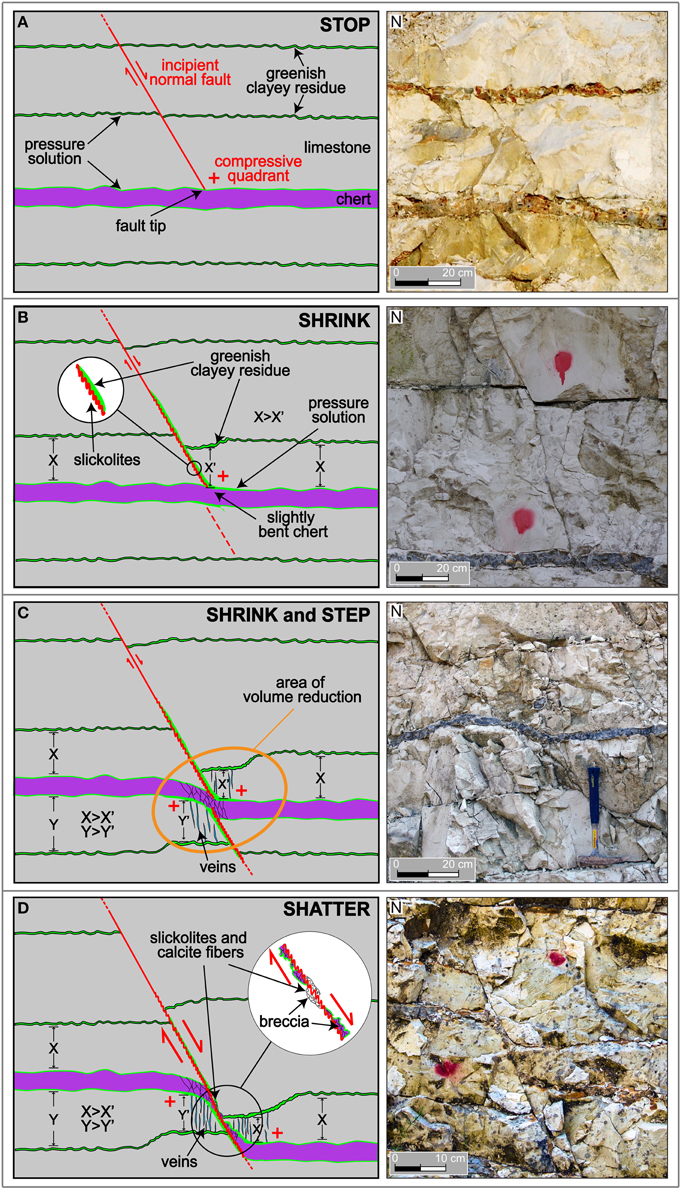
Figure 14. Conceptual model of fault post-nucleation growth in four steps. (A) Stop: the faults stopped at the competent chert beds. (B) Shrink: faulting produced shrinkage (pressure solution) of carbonate beds at the fault compressive terminations. (C) Shrink and Step: while shrinkage by pressure solution continued, the faults stepped laterally at the competent chert beds. (D) Shatter: the chert beds were shattered along the fault surfaces.
As final synthesis, we propose a photograph (Figure 15A) where the above-discussed steps of fault growth are all present within an outcrop area of about 15 m2. We interpret this photograph as a snapshot of nascent polygonal faults in close proximity within carbonate beds, with the chert layers acting both as opponents to the fault propagation and as indirect promoters of new fault nucleation in the carbonates to accommodate the ongoing stretching strain (Figures 14, 15A). As explained above, this snapshot (Figure 15A) is located in the hinge of the Cingoli triply-folded anticline (Figures 15B,C), where this particular geometry may explain the last open question that we propose in this paper: why have polygonal normal faults, as those observed in the Scaglia Bianca Fm. from the Cingoli anticline, not been hitherto observed in similar lithologies in other anticlines of the Apennines fold-thrust belt? In addition to the exposure availability, the only plausible explanation that we can find is in the structural position of the study outcrop within the Cingoli anticline and in the particular geometry of this fold (Figures 15C) that is characterized by a short axis with lateral periclinal closures and by one of the greatest map-view curvature among the central-northern Apennines anticlines (Table A1). In other words, the anticline underwent a syn-thrusting progressive triple folding process that is probably not as common. This may explain the uniqueness, so far, of the Cingoli polygonal faults.
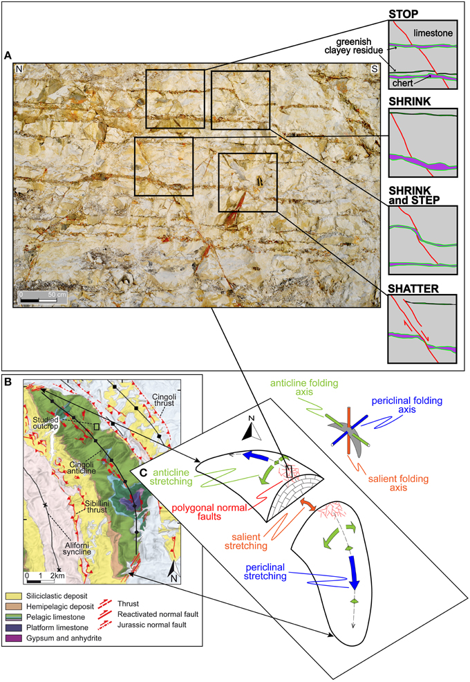
Figure 15. (A) Final synthetic photograph and fault growth model. This photograph, where the steps of fault growth shown in the model of Figure 14 are all present within an outcrop area of about 15 m2, represents a snapshot of nascent polygonal faults in close proximity within carbonate beds. In this setting, the chert layers acted both as opponents to the fault propagation and as indirect promoters of new fault nucleation in the carbonates to accommodate the ongoing stretching strain at the extrados of the developing Cingoli anticline. This snapshot is contextualized within (B) the geological map of the Cingoli anticline (same as Figure 2B) and (C) a three-dimensional model of the triply-folded anticline. In the anticline hinge and crestal region, note the three stretching axes normal to the three folding axes (anticline, periclinal, and salient).
Conclusions
(1) The normal faults exposed in the Cingoli anticline hinge are polygonal faults geometrically and kinematically similar to the polygonal normal faults known in the North Sea basin and in many other marine settings.
(2) The Cingoli polygonal faults primarily developed in response to syn-thrusting stretch processes occurred at the anticline hinge during fold formation. As such, these structures are the first reported polygonal normal faults developed syn-tectonically rather than syn-diagenetically.
(3) The Cingoli polygonal faults enhanced bed-parallel pressure solution at their tips. While the cause of these faults is the tensile stress at the Cingoli anticline extrados, the process by which the fault displacement was accomplished is at least in part pressure solution. This process, which is conceptually similar to syneresis that has been often hypothesized for polygonal fault formation, is new for polygonal faults.
(4) Syn-thrusting, normal fault-related, bed-parallel pressure solution on sub-horizontal carbonate beds, as is the case of the Cingoli anticline hinge, is an unprecedented or very rare case in syn-orogenic settings. This process can lead to clay concentrations in anticline hinges, as observed in this study case, thus potentially influencing geofluid flow and entrapment in buried carbonate anticlines.
(5) Although the origin of the Cingoli polygonal faults is substantially different from that of the polygonal faults previously-studied in marine basins (i.e., tectonic vs. diagenetic origins), the ones analyzed in this paper are among the few known exposed polygonal faults and, as such, they may result useful to better understand and characterize those buried in marine basins. For example, the fault abundance appears to be significantly different when measured on outcrop (Cingoli) and on seismic image (North Sea basin) chiefly as a function of observation scales. The outcrop described in this paper is available for further direct analyses and measurements that may serve as subseismic analog of marine basins affected by normal faults.
(6) The observed finite deformation connected with the Cingoli polygonal faults is very complex resulting from syn-thrusting progressive multi-polarity stretching deformation, interaction between adjacent structures, volume loss, and space- and time-varying rheologies dominated by the alternate carbonate-chert beds and influenced by the progressive clay concentration. The model presented in this work is a general one explaining the overall deformation associated with the Cingoli faults. To restore the complex finite deformation a further dedicated work will be necessary.
Conflict of Interest Statement
The authors declare that the research was conducted in the absence of any commercial or financial relationships that could be construed as a potential conflict of interest.
Acknowledgments
We warmly thank S. Kusumoto, A. Noda, K. Sato and A. M. Michetti for editorial handling and scientific reviews that greatly improved our manuscript. We also thank S. Stellino for XRD analyses in the X-ray powder diffraction Laboratory of Dipartimento di Scienze della Terra, Sapienza University of Rome.
References
Alves, T. M. (2010). 3D Seismic examples of differential compaction in mass-transport deposits and their effect on post-failure strata. Mar. Geol. 271, 212–224. doi: 10.1016/j.margeo.2010.02.014
Amrouch, K., Lacombe, O., Bellahsen, N., Daniel, J. M., and Callot, J. P. (2010a). Stress and strain patterns, kinematics and deformation mechanisms in a basement-cored anticline: Sheep Mountain Anticline, Wyoming. Tectonics 29, TC1005. doi: 10.1029/2009TC002525
Amrouch, K., Robion, P., Callot, J. P., Lacombe, O., Daniel, J. M., Bellahsen, N., et al. (2010b). Constraints on deformation mechanisms during folding provided by rock physical properties: a case study at Sheep Mountain anticline (Wyoming, USA). Geophys. J. Int. 182, 1105–1123. doi: 10.1111/j.1365-246X.2010.04673.x
Andresen, K. J., and Huse, M. (2011). ‘Bulls-eye’ pock marks and polygonal faulting in the Lower Congo Basin: relative timing and implications for fluid expulsion during shallow burial. Mar. Geol. 279, 111–127. doi: 10.1016/j.margeo.2010.10.016
Antonellini, M., Petracchini, L., Billi, A., and Scrocca, D. (2014). First reported occurrence of deformation bands in a platform limestone, the Jurassic Calcare Massiccio Fm., northern Apennines, Italy. Tectonophysics 628, 85–104. doi: 10.1016/j.tecto.2014.04.034
Arthur, M. A., and Fischer, A. G. (1977). Upper Cretaceous-Paleocene magnetic stratigraphy at Gubbio, Italy. I Lithostratigraphy and sedimentology. Geol. Soc. Am. Bull. 88, 367–371.
Arts, R., Eiken, O., Chadwick, A., Zweigel, P., Van der Meer, B., and Kirby, G. (2004). “Seismic monitoring at the Sleipner underground CO2 storage site (North Sea),” in Geological Storage of Carbon Dioxide, Vol. 233, eds S. J. Baines, and R. H. Worden (London: Geological Society, Special Publication), 181–191.
Bally, A. W., Burbi, L., Cooper, C., and Ghelardoni, R. (1986). Balanced sections and seismic reflection profiles across the Central Apennines. Mem. Soc. Geol. It. 35, 257–310.
Beaudoin, N., Leprêtre, R., Bellahsen, N., Lacombe, O., Amrouch, K., Callot, J. P., et al. (2012). Structural and microstructural evolution of the Rattlesnake Mountain Anticline (Wyoming, USA): new insights into the Sevier and Laramide orogenic stress build-up in the Bighorn Basin. Tectonophysics 576, 20–45. doi: 10.1016/j.tecto.2012.03.036
Bellahsen, N., Fiore, P., and Pollard, D. D. (2006). The role of fractures in the structural interpretation of Sheep Mountain Anticline, Wyoming. J. Struct. Geol. 28, 850–867. doi: 10.1016/j.jsg.2006.01.013
Bigi, G., Bonardi, G., Catalano, R., Cosentino, D., Lentini, F., Parotto, M., et al. (eds.). (1992). Structural Model of Italy 1:500,000, Consiglio Nazionale delle Ricerche, Progetto Finalizzato Geodinamica. Florence: Selca.
Billi, A. (2003). Solution slip and separations on strike-slip fault zones: theory and application to the Mattinata Fault, Italy. J. Struct. Geol. 25, 703–715. doi: 10.1016/S0191-8141(02)00077-9
Billi, A. (2005). Attributes and influence on fluid flow of fractures in foreland carbonates of southern Italy. J. Struct. Geol. 27, 1630–1643. doi: 10.1016/j.jsg.2005.05.001
Billi, A., Porreca, M., Faccenna, C., and Mattei, M. (2006). Magnetic and structural constraints for the non-cylindrical evolution of a continental forebulge (CityHyblea, Italy). Tectonics 25, TC3011. doi: 10.1029/2005TC001800
Billi, A., and Salvini, F. (2003). Development of systematic joints in response to flexure-related fibre stress in flexed foreland plates: the Apulian forebulge case history, Italy. J. Geodyn. 36, 523–536. doi: 10.1016/S0264-3707(03)00086-3
Billi, A., Valle, A., Brilli, M., Faccenna, C., and Funiciello, R. (2007). Fracture-controlled fluid circulation and dissolutional weathering in sinkhole-prone carbonate rocks from central Italy. J. Struct. Geol. 29, 385–395. doi: 10.1016/j.jsg.2006.09.008
Bureau, D., Mourgues, R., Cartwright, J., Foschi, M., and Abdelmalak, M. M. (2013). Characterisation of interactions between a pre-existing polygonal fault system and sandstone intrusions and the determination of paleo-stresses in the Faroe-Shetland basin. J. Struct. Geol. 46, 186–199. doi: 10.1016/j.jsg.2012.09.003
Calamita, F., Cello, G., Invernizzi, C., and Paltrinieri, W. (1990). Stile strutturale e cronologia della deformazione lungo la traversa M.S. Vicino – Polverigi (Appennino marchigiano esterno). Studi Geol. Cam. Spec. 1, 69–86.
Carloni, G. C. (1964). La Geologia dei dintorni di Cingoli (Appennino Marchigiano). Giorn. Geol. 32, 365–401.
Carminati, E., Scrocca, D., and Doglioni, C. (2010). Compaction-induced stress variations with depth in an active anticline: Northern Apennines. Italy. J. Geophys. Res. 115, B02401. doi: 10.1029/2009jb006395
Cartwright, J. (2014). Are outcrop studies the key to understanding the origins of polygonal fault systems? Geology 42, 559–560. doi: 10.1130/focus062014.1
Cartwright, J. A. (1994a). Episodic basin-wide hydrofracturing of overpressured early Cenozoic mudrock sequences in the North Sea Basin. Mar. Petrol. Geol. 11, 587–607. doi: 10.1016/0264-8172(94)90070-1
Cartwright, J. A. (1994b). Episodic basin-wide fluid expulsion from geopressured shale sequences in the North Sea Basin. Geology 22, 447–450.
Cartwright, J. A. (2011). Diagenetically-induced shear failure of fine-grained sediments and the development of polygonal fault systems. Mar. Petrol. Geol. 28, 1593–1610. doi: 10.1016/j.marpetgeo.2011.06.004
Cartwright, J. A., and Dewhurst, D. (1998). Layer-bound compaction faults in fine-grained sediments. Geol. Soc. Am. Bull. 110, 1242–1257.
Cartwright, J. A., Huuse, M., and Aplin, A. (2007). Topseal bypass systems. AAPG Bull. 91, 1141–1166. doi: 10.1306/04090705181
Cartwright, J. A., James, D. M. D., and Bolton, A. J. (2003). “The genesis of polygonal fault systems: a review,” in Subsurface Sediment Mobilisation, Vol. 216, eds P. Van Rensbergen, R. Hillis, and C. Morley (London: Geological Society, Special Publication), 223–242. doi: 10.1144/GSL.SP.2003.216.01.15
Cartwright, J. A., and Lonergan, L. (1996). Volumetric contraction during the compaction of mudrocks: a mechanism for the development of regional-scale polygonal fault systems. Bas. Res. 8, 183–193. doi: 10.1046/j.1365-2117.1996.01536.x
Cartwright, J. A., Trudgill, B. D., and Mansfield, C. (1995). An explanation for the scatter in displacement and length data during fault growth by segment linkage. J. Struct. Geol. 17, 672–679. doi: 10.1016/0191-8141(95)00033-A
Chiarabba, C., Jovane, L., and Di Stefano, R. (2005). A new view of Italian seismicity using 20 years of instrumental recordings. Tectonophysics 395, 251–268. doi: 10.1016/j.tecto.2004.09.013
Ciancetti, G., and Nanni, T. (1989). Note sulla Geologia dell'anticlinale di Monte Acuto di Cingoli (Marche). Boll. Soc. Geol. It. 108, 553–564.
Coccioni, R., and Galeotti, S. (2003). The mid-Cenomanian Event: prelude to OAE 2. Palaeogeogr. Palaeoclimatol. Palaeoecol. 190, 427–440. doi: 10.1016/S0031-0182(02)00617-X
Cosgrove, J. W. (1998). “The role of structural geology in reservoir characterization,” in Structural Geology in Reservoir Characterization, Vol. 127, eds M. P. Coward, T. S. Daltaban, and H. Johnson (London: Geological Society, Special Publication), 1–13. doi: 10.1144/gsl.sp.1998.127.01.01
Cotterell, B., and Rice, J. R. (1980). Slightly curved or kinked cracks. Int. J. Fract. 16, 155–169. doi: 10.1007/BF00012619
Cruikshank, K. M., and Aydin, A. (1994). Role of fracture localization in arch formation, Arches National Park, Utah. Geol. Soc. Am. Bull. 106, 879–891.
Cruikshank, K. M., Zhao, G., and Johnson, A. M. (1991). Analysis of minor fractures associated with joints and faulted joints. J. Struct. Geol. 13, 865–886. doi: 10.1016/0191-8141(91)90083-U
Davies, R. J., and Cartwright, J. A. (2007). Kilometer-scale chemical reaction boundary patterns and deformation in sedimentary rocks. Earth Planet. Sci. Lett. 262, 125–137. doi: 10.1016/j.epsl.2007.07.042
Davies, R. J., and Ireland, M. T. (2011). Initiation and propagation of polygonal fault arrays by thermally triggered volume reduction reactions in siliceous sediment. Mar. Geol. 289, 150–158. doi: 10.1016/j.margeo.2011.05.005
Davies, R. J., Ireland, M. T., and Cartwright, J. A. (2009). Differential compaction due to the irregular topology of a diagenetic reaction boundary: a new mechanism for the formation of polygonal faults. Bas. Res. 21, 354–359. doi: 10.1111/j.1365-2117.2008.00389.x
Davis, G. H., and Reynolds, S. J. (1996). Structural Geology of Rocks and Regions. New York, NY: Wiley.
Dawers, N. H., and Anders, M. H. (1995). Displacement-length scaling and fault linkage. J. Struct. Geol. 17, 607–614. doi: 10.1016/0191-8141(94)00091-D
Dawers, N. H., Anders, M. H., and Scholz, C. H. (1993). Growth of normal faults: displacement-length scaling. Geology 21, 1107–1110.
Dehandschutter, B., Gaviglio, P., Sizun, J.-P., Sintubin, M., Vandycke, S., Vendenberge, N., et al. (2005). Volumetric matrix strain related to intraformational faulting in argillaceous sediments. J. Geol. Soc. Lond. 162, 801–813. doi: 10.1144/0016-764904-093
Deiana, G., Cello, G., Chiocchini, M., Galdenzi, S., Mazzoli, S., Pistolesi, E., et al. (2002). Tectonic evolution of the external zones of the Umbria-Marche Apennines in the Monte San Vicino-Cingoli area. Boll. Soc. Geol. It. Spec. 1, 229–238.
Dewhurst, D., Cartwright, J. A., and Lonergan, L. (1999). The development of polygonal fault systems by the syneresis of fine-grained sediments. Mar. Petrol. Geol. 16, 793–810. doi: 10.1016/S0264-8172(99)00035-5
Dietrich, D. (1989). Fold-axis parallel extension in an arcuate fold-and thrust belt: the case of the Helvetic nappes. Tectonophysics 170, 183–212. doi: 10.1016/0040-1951(89)90271-0
Erdogan, F., and Sih, G. H. (1963). On the crack extension in plates under plane loading and transverse shear. J. Bas. Eng. 85, 519–527. doi: 10.1115/1.3656897
Fischer, M. P., and Wilkerson, M. S. (2000). Predicting the orientation of joints from fold shape: results of pseudo-three-dimensional modeling and curvature analysis. Geology 28, 15–18. doi: 10.1130/0091-7613(2000)28<15:PTOOJF>2.0.CO;2
Fletcher, R. C., and Pollard, D. D. (1981). Anticrack model for pressure solution surfaces. Geology 9, 419–424.
Fossen, H., and Hesthammer, J. (1997). Geometric analysis and scaling relations of deformation bands in porous sandstone. J. Struct. Geol. 19, 1479–1493. doi: 10.1016/S0191-8141(97)00075-8
Gay, A., and Berndt, C. (2007). Cessation/reactivation of polygonal faulting and effects on fluid flow in the Vøring Basin, Norwegian Margin. J. Geol. Soc. Lond. 164, 129–141. doi: 10.1144/0016-76492005-178
Gay, A., Lopez, M., Cochonat, P., Séranne, M., Levaché, D., and Sermondadaz, G. (2006). Isolated seafloor pockmarks linked to BSRs, fluid chimneys, polygonal faults and stacked Oligocene–Miocene turbiditic palaeochannels in the Lower Congo Basin. Mar. Geol. 226, 25–40. doi: 10.1016/j.margeo.2005.09.018
Gay, A., Lopez, M., Cochonat, P., and Sermondadz, G. (2004). Polygonal faults-furrows system related to early stages of compaction - upper Miocene to recent sediments of the Lower Congo Basin. Bas. Res. 16, 101–116. doi: 10.1111/j.1365-2117.2003.00224.x
Goulty, N. J. (2001). Mechanics of layer-bound polygonal faulting in fine-grained sediments. J. Geol. Soc. Lond. 159, 239–246. doi: 10.1144/0016-764901-111
Goulty, N. J. (2008). Geomechanics of polygonal fault systems: a review. Petrol. Geosci. 14, 389–397. doi: 10.1144/1354-079308-781
Goulty, N. J., and Swarbrick, R. E. (2005). Development of polygonal fault systems, a test of hypotheses. J. Geol. Soc. Lond. 162, 579–590. doi: 10.1144/0016-764905-004
Gratier, J.-P., Noiriel, C., and Renard, F. (2015). Experimental evidence for rock layering development by pressure solution. Geology 43, 871–874, doi: 10.1130/G36713.1
Gudmundsson, A. (2011). Rock Fractures in Geological Processes. Cambridge: Cambridge University Press.
Gudmundsson, A., De Guidi, G., and Scudero, S. (2013). Length–displacement scaling and fault growth. Tectonophysics 608, 1298–1309. doi: 10.1016/j.tecto.2013.06.012
Gudmundsson, A., Simmenes, T. H., Larsen, B., and Philipp, S. L. (2010). Effects of internal structure and local stresses on fracture propagation, deflection, and arrest in fault zones. J. Struct. Geol. 32, 1643–1655. doi: 10.1016/j.jsg.2009.08.013
Henriet, J. P., Batist, M. D., and Verschuren, M. (1991). “Early fracturing of Paleogene clays, southernmost North Sea: relevance to mechanisms of primary hydrocarbon migration,” in Generation, Accumulation and Production of Europe's Hydrocarbons, Vol. 1, ed A. M. Spenser (Oxford: Special Publication of the European Association of Petroleum Geologists), 217–227.
Hibsch, C., Cartwright, J. A., Hansen, D., Gaviglio, P., André, G., Cushing, M., et al. (2003). “Normal faulting in chalk: tectonic stresses vs. compaction-related polygonal faulting,” in Subsurface Sediment Mobilization, Vol. 216, eds P. Van Rensbergen, R. R. Hillis, A. J. Maltman, and C. K. Morley (London: Geological Society, Special Publication), 291–308.
Homberg, C., Hu, J. C., Angelier, J., Bergerat, F., and Lacombe, O. (1997). Characterization of stress perturbations near major fault zones: insights from 2-D distinct-element numerical modelling and field studies (Jura mountains). J. Struct. Geol. 19, 703–718. doi: 10.1016/S0191-8141(96)00104-6
Ireland, M., Goulty, N. J., and Davies, R. J. (2010). Influence of pore water chemistry on silica diagenesis: evidence from the interaction of diagenetic reaction zones with polygonal fault systems. J. Geol. Soc. Lond. 167, 273–279. doi: 10.1144/0016-76492009-049
Jackson, C. A. L., Carruthers, D. T., Mahlo, S. N., and Briggs, O. (2014). Can polygonal faults help locate deep-water reservoirs? AAPG Bull. 98, 1717–1738. doi: 10.1306/03131413104
Kim, Y.-S., and Sanderson, D. J. (2005). The relationship between displacement and length of faults: a review. Earth-Sci. Rev. 68, 317–334. doi: 10.1016/j.earscirev.2004.06.003
Lacombe, O., Angelier, J., Chen, H.-W., Deffontaines, B., Chu, H.-T., and Rocher, M. (1997). Syndepositional tectonics and extension-compression relationships at the front of the Taiwan collision belt: a case study in the Pleistocene reefal limestones near Kaohsiung, SW Taiwan. Tectonophysics 274, 83–96. doi: 10.1016/S0040-1951(96)00299-5
Lawn, B. R., and Wilshaw, T. R. (1975). Fracture of Brittle Solids. New York, NY: Cambridge University Press.
Livio, F. A., Berlusconi, A., Zerboni, A., Trombino, L., Sileo, G., Michetti, A. M., et al. (2014). Progressive offset and surface deformation along a seismogenic blind thrust in the Po Plain foredeep (Southern Alps, Northern Italy). J. Geophys. Res. 119, 7701–7721. doi: 10.1002/2014JB011112
Lonergan, L., Cartwright, J. A., and Jolley, R. (1998). 3-D geometry of polygonal fault systems. J. Struct. Geol. 20, 529–548. doi: 10.1016/S0191-8141(97)00113-2
Marchegiani, L., Bertotti, G., Cello, G., Deiana, G., Mazzoli, S., and Tondi, E. (1999). Pre-orogenic tectonics in the Umbria-Marche sector of the Afro-Adriatic continental margin. Tectonophysics 315, 123–143. doi: 10.1016/S0040-1951(99)00277-2
Mazzoli, S., Deiana, G., Galdenzi, S., and Cello, G. (2002). Miocene fault-controlled sedimentation and thrust propagation in the previously faulted external zones of the Umbria–Marche Apennines, Italy. EGU Stephan Mueller Spec. Publ. 1, 195–209. doi: 10.5194/smsps-1-195-2002
Meadows, D., and Davies, R. J. (2009). Predicting porosity reduction due to silica diagenesis using seismic reflection data. Mar. Petrol. Geol. 26, 1543–1553. doi: 10.1016/j.marpetgeo.2008.09.006
Menichetti, M. (1991). La sezione geologica Cingoli-M.Maggio-Tevere nell'Appennino umbro-marchigiano: analisi cinematica e strutturale. Studi Geol. Cam. Spec. 1, 315–328.
Møller Hansen, D., Shimeld, J. W., Williamson, M. A., and Lykke-Andersen, H. (2004). Development of a major polygonal fault system in Upper Cretaceous chalk and Cenozoic mudrocks of the Sable Subbasin, Canadian Atlantic margin. Mar. Petrol. Geol. 21, 1205–1219. doi: 10.1016/j.marpetgeo.2004.07.004
Montone, P., Mariucci, M. T., and Pierdominici, S. (2012). The Italian present-day stress map. Geophys. J. Int. 189, 705–716. doi: 10.1111/j.1365-246X.2012.05391.x
Petracchini, L., Antonellini, M., Billi, A., and Scrocca, D. (2012). Fault development through fracture pelagic carbonates of the Cingoli anticline, Italy: possible analog for subsurface fluid-conductive fractures. J. Struct. Geol. 45, 21–37. doi: 10.1016/j.jsg.2012.05.007
Petracchini, L., Antonellini, M., Billi, A., Scrocca, D., Trippetta, F., and Mollo, S. (2015). Pressure solution inhibition in a limestone–chert composite multilayer: implications for the seismic cycle and fluid flow. Tectonophysics 646, 96–105. doi: 10.1016/j.tecto.2015.02.005
Pohn, H. A. (1981). Joint spacing as a method of locating faults. Geology 9, 258–261. doi: 10.1130/0091-7613(1981)9<258:JSAAMO>2.0.CO;2
Pollard, D. D., and Segall, P. (1987). “Theoretical displacements and stresses near fractures in rock: with applications to faults, joints, veins, dikes, and solution surfaces,” in Fracture Mechanics of Rock, ed B. K. Atkinson (London: Academic Press), 277–349.
Price, N. J., and Cosgrove, J. W. (1990). Analysis of Geological Structures. Cambridge: Cambridge University Press.
Roche, V., Homberg, C., and Rocher, M. (2012). Architecture and growth of normal fault zones in multilayer systems: a 3D field analysis in the South-Eastern Basin, France. J. Struct. Geol. 37, 19–35. doi: 10.1016/j.jsg.2012.02.005
Rocher, M., Lacombe, O., Angelier, J., and Chen, H.-W. (1996). Mechanical twin sets in calcite as markers of recent collisional events in a fold-and-thrust belt: evidence from the reefal limestones of southwestern Taiwan. Tectonics 15, 984–996. doi: 10.1029/96TC00625
Rossetti, F., Tecce, F., Billi, A., and Brilli, M. (2007). Patterns of fluid flow in the contact aureole of the late Miocene Monte Capanne pluton (Elba Island, Italy): the role of structures and rheology. Contrib. Mineral. Petrol. 153, 743–760. doi: 10.1007/s00410-006-0175-3
Santantonio, M. (1993). Facies associations and evolution of pelagic platform/basin systems: examples from the Italian Jurassic. Sedimentology 40, 1039–1067. doi: 10.1111/j.1365-3091.1993.tb01379.x
Santantonio, M. (1994). Pelagic carbonate platforms in the geologic record: their classification, and sedimentary and paleotectonic evolution. AAPG Bull. 78, 122–141.
Savage, H. M., Shackleton, R. J., Cooke, M. L., and Riedel, J. J. (2010). Insights into fold growth using fold-related joint patterns and mechanical stratigraphy. J. Struct. Geol. 32, 1466–1475. doi: 10.1016/j.jsg.2010.09.004
Scrocca, D., Carminati, E., Doglioni, C., and Marcantoni, D. (2007). “Slab retreat and active shortening along the central-northern Apennines,” in Thrust Belts and Foreland Basins: From Fold Kinematics to Hydrocarbon Systems, eds O. Lacombe, J. Lavé, F. Roure, and J. Vergés (Berlin: Elsevier; Frontiers in Earth Sciences), 471–487.
Shackleton, J. R., Cooke, M. L., Vergés, J., and Simó, T. (2011). Temporal constraints on fracturing associated with fault-related folding at Sant Corneli anticline, Spanish Pyrenees. J. Struct. Geol. 33, 5–19. doi: 10.1016/j.jsg.2010.11.003
Shoulders, S. J., Cartwright, J. A., and Huuse, M. (2007). Large-scale conical sandstone intrusions and polygonal fault systems in Tranche 6, Faroe-Shetland Basin. Mar. Petrol. Geol. 24, 173–188. doi: 10.1016/j.marpetgeo.2006.12.001
Soliva, R., and Benedicto, A. (2005). Geometry, scaling relations and spacing of vertically restricted normal faults. J. Struct. Geol. 27, 317–325. doi: 10.1016/j.jsg.2004.08.010
Soliva, R., Schultz, R. A., and Benedicto, A. (2005). Three-dimensional displacement-length scaling and maximum dimension of normal faults in layered rocks. Geophys. Res. Lett. 32, L16302. doi: 10.1029/2005GL023007
Storti, F., and Salvini, F. (2001). The evolution of a model trap in the Central Apennines, Italy: fracture patterns, fault reactivation and development of cataclastic rocks in carbonates at the Narni Anticline. J. Pet. Geol. 24, 171–190. doi: 10.1111/j.1747-5457.2001.tb00666.x
Tavani, S., Arbues, P., Snidero, M., Carrera, N., and Muñoz, J. A. (2011). Open Plot Project: an open-source toolkit for 3-D structural data analysis. Solid Earth 2, 53–63. doi: 10.5194/se-2-53-2011
Tavani, S., Storti, F., Bausà, J., and Muñoz, J. A. (2012). Late thrusting extensional collapse at the mountain front of the northern Apennines (Italy). Tectonics 31, TC4019. doi: 10.1029/2011TC003059
Tavani, S., Storti, F., Lacombe, O., Corradetti, A., Muñoz, J. A., and Mazzoli, S. (2015a). A review of deformation pattern templates in foreland basin systems and fold-and-thrust belts: implications for the state of stress in the frontal regions of thrust wedges. Earth Sci. Rev. 141, 82–104. doi: 10.1016/j.earscirev.2014.11.013
Tavani, S., Storti, F., Salvini, F., and Toscano, C. (2008). Stratigraphic versus structural control on the deformation pattern associated with the evolution of the Mt. Catria anticline, Italy. J. Struct. Geol. 30, 664–681. doi: 10.1016/j.jsg.2008.01.011
Tavani, S., Vignaroli, G., and Parente, M. (2015b). Transverse vs. longitudinal extension in the foredeep-peripheral bulge system: role of Cretaceous structural inheritances during Early Miocene extensional faulting in inner central Apennines Belt. Tectonics 34, 1412–1430. doi: 10.1002/2015TC003836
Tavarnelli, E. (1997). Structural evolution of a foreland fold-and-thrust belt: the Umbria-Marche Apennines, Italy. J. Struc. Geol. 19, 523–534. doi: 10.1016/S0191-8141(96)00093-4
Tewksbury, B. J., Hogan, J. P., Kattenhorn, S. A., Mehrtens, C. J., and Tarabees, E. A. (2014). Polygonal faults in chalk: insights from extensive exposures of the Khoman Formation, Western Desert, Egypt. Geology 42, 479–482. doi: 10.1130/G35362.1
Titley, S. R. (1976). Evidence for a Mesozoic linear tectonic pattern in southeastern Arizona. Arizona Geol. Soc. Digest. 10, 71–101.
Vejbæk, O. V., Rasmussen, R., Japsen, P., Bruun, A., Pedersen, J. M., Marsden, G., et al. (2005). “Seismic Response from North Sea chalk,” in Petroleum Geology: North-West Europe and Global Perspectives, eds A. G. Doré, and B. A. Vining (London: Geological Society, Proceedings of the 6th Petroleum Geology Conference), 1401–1413.
Ventura, G., and Di Giovambattista, R. (2013). Fluid pressure, stress field and propagation style of coalescing thrusts from the analysis of the 20 May 2012 ML5.9 Emilia earthquake (Northern Apennines, Italy). Terra Nova 25, 72–78. doi: 10.1111/ter.12007
Victor, P., and Moretti, I. (2006). Polygonal fault systems and channel boudinage: 3D analysis of multidirectional extension in analogue sandbox experiments. Mar. Petrol. Geol. 23, 777–789. doi: 10.1016/j.marpetgeo.2006.06.004
Vollmer, F. W. (1995). C program for automatic contouring of spherical orientation data using a modified Kamb method. Comput. Geosci. 21, 31–49. doi: 10.1016/0098-3004(94)00058-3
Watterson, J. (1986). Fault dimensions, displacements and growth. Pure Appl. Geophys. 124, 365–363. doi: 10.1007/BF00875732
Watterson, J., Walsh, J. J., Nicol, A., Nell, P. R., and Bretan, P. G. (2000). Geometry and origin of a polygonal fault system. J. Geol. Soc. Lond. 157, 151–162. doi: 10.1144/jgs.157.1.151
Wheeler, R. L., and Dixon, J. M. (1980). Intensity of systematic joints, methods and applications. Geology 8, 230–233.
Willemse, E. J. M., and Pollard, D. D. (1998). On the orientation and patterns of wing cracks and solution surfaces at the tips of a sliding flaw or fault. J. Geophys. Res. 103, 2427–2438. doi: 10.1029/97JB01587
Zaoui, A., and Sekkal, W. (2015). Can clays ensure nuclear waste repositories? Scient. Rep. 5:8815. doi: 10.1038/srep08815
Appendix
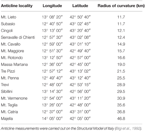
Table A1. Horizontal radius of curvature (map view) for the 16 most arcuate (salient-like) anticlines of central-northern Apennines, Italy.
Keywords: polygonal faults, normal faults, pressure solution, anticline, fold-thrust belt, carbonate, chert, Apennines
Citation: Petracchini L, Antonellini M, Billi A and Scrocca D (2015) Syn-thrusting polygonal normal faults exposed in the hinge of the Cingoli anticline, northern Apennines, Italy. Front. Earth Sci. 3:67. doi: 10.3389/feart.2015.00067
Received: 02 July 2015; Accepted: 21 October 2015;
Published: 05 November 2015.
Edited by:
Shigekazu Kusumoto, University of Toyama, JapanReviewed by:
Alessandro Maria Michetti, Università degli Studi dell'Insubria, ItalyAtsushi Noda, Geological Survey of Japan, Japan
Katsushi Sato, Kyoto University, Japan
Copyright © 2015 Petracchini, Antonellini, Billi and Scrocca. This is an open-access article distributed under the terms of the Creative Commons Attribution License (CC BY). The use, distribution or reproduction in other forums is permitted, provided the original author(s) or licensor are credited and that the original publication in this journal is cited, in accordance with accepted academic practice. No use, distribution or reproduction is permitted which does not comply with these terms.
*Correspondence: Andrea Billi, andrea.billi@cnr.it