Interaction between Transform Faults and Rift Systems: A Combined Field and Experimental Approach
 Alessandro Tibaldi
 Fabio L. Bonali1
  Federico A. Pasquaré Mariotto
- 1Department of Earth and Environmental Sciences, University of Milan-Bicocca, Milan, Italy
- 2Department of Theoretical and Applied Sciences, Insubria University, Varese, Italy
We present a detailed field structural survey of the area of interaction between the active NW-striking transform Husavik-Flatey Fault (HFF) and the N–S Theystareykir Fissure Swarm (TFS), in North Iceland, integrated by analog scaled models. Field data contribute to a better understanding of how transform faults work, at a much higher detail than classical marine geophysical studies. Analog experiments are conducted to analyse the fracture patterns resulting from different possible cases where transform faulting accompanies or postpones the rift motions. Different tectonic block configurations are also considered and results are compared with field data in order to study as thoroughly as possible the interaction between the HFF and the TFS as well as the possible prolongation of the HFF into the TFS. West of the intersection between the transform fault (HFF) and the rift zone (TFS), the former splays with a gradual bending giving rise to a leading extensional imbricate fan. The westernmost structure of the rift, the N–S Gudfinnugja Fault (GF), is divided into two segments: the southern segment makes a junction with the HFF and is part of the imbricate fan; north of the junction instead, the northern GF appears right-laterally offset by about 20 m. Southeast of the junction, along the possible prolongation of the HFF across the TFS, the strike of the rift faults rotates in an anticlockwise direction, attaining a NNW–SSE orientation. Moreover, the TFS faults north of the HFF prolongation are fewer and have smaller offsets than those located to the south. Through the comparison between the structural data collected in the field at the HFF–TFS connection zone and a set of scaled experiments, we confirm a prolongation of the HFF through the rift, although here the transform fault has a much lower slip-rate than west of the junction. Our data suggest that transform fault terminations may be more complex than previously known, and propagate across a rift through a modification of the rift pattern.
Introduction
A transform fault is characterized by strike-slip motions that end abruptly and are turned into deformation at a companion structure. A classic example is given by a transform fault that merges into an expanding rift (Wilson, 1965). This type of intersection zone has been studied mainly by geophysical surveys in marine environments, using bathymetric maps and earthquake data. As a consequence, hardly ever available data are detailed enough to allow for a precise evaluation of the geometry, kinematics, and deformation at the termination of transform faults. Moreover, several mechanisms have been proposed to describe how such strike-slip faults terminate, but they are poorly resolved in several cases. More detailed data on transform fault terminations have been collected and studied on-land, especially in regard to the transition to reverse fault/trench systems (e.g., Davis and Burchfiel, 1973; Bellier and Sebrier, 1995; Quebral et al., 1996; Tsutsumi and Okada, 1996; Freymueller et al., 1999; Norris and Cooper, 2000), while fewer are related to on-land rift zones (e.g., Joffe and Garfunkel, 1987; Mouslopoulou et al., 2007a).
Terminations of transform faults can be of four main types: (i) the fault can end at the tip without any apparent connection with any other structure, with some secondary faults that can depart for a short distance, but the rock volume surrounding the fault tip appears basically not faulted at a regional scale of observation (Mouslopoulou et al., 2007b; Figure 1A); (ii) the transform fault ends via a branching of the main fault plane into a splay (Figure 1B). In this case, the main fault bends into a series of secondary faults with different orientations, decreasing the displacement on the main transform fault and redistributing the slip into the rock volume located on one side of the fault plane. Based on the geometry of the splay and the kinematics of the main fault, the resulting configuration can be an extensional or a contractional imbricate fan (Woodcock and Fischer, 1986); (iii) the transform fault tip coincides with the tip of a normal or a reverse fault (Figure 1C). An example can be observed at the intersection between the Sumatra Fault in Indonesia and the Sunda Strait Rift (Lelgemann et al., 2000), and at the tip coinciding with the Median Tectonic Line and the Yatsushiro graben in Japan (Kamata and Kodama, 1994); (iv) the transform fault terminates in correspondence of a through-going reverse or normal fault system (Figure 1D). This configuration can be observed, for example, where the Dead Sea fault intersects the Red Sea Rift (Joffe and Garfunkel, 1987).
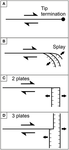
Figure 1. Schematic diagram illustrating the four basic types of strike-slip fault terminations. (A) The strike-slip fault ends at a tip surrounded by undeformed rocks; (B) the strike-slip fault terminates with a splay, which in this example creates a transtensional zone; (C) the strike-slip fault terminates in correspondence of a normal or reverse fault; (D) the strike-slip fault terminates against another through-going fault system. (A, C, and D modified after Mouslopoulou et al., 2007a).
Several examples of transform-rift interaction may be related to case (ii), such as at the intersection of the East Pacific Rise with the Tamayo Transform Fault (Gallo et al., 1984), the Siqueiros Transform fault system with the East Pacific Rise (Fornari et al., 1989), the Vema Fracture Zone (Mamaloukas-Frangoulis et al., 1991), the Oceanographer Transform fault (Karson et al., 1984) with the Mid-Atlantic Ridge, and several other sites (review in Şengör, 2014). This type of configuration is stable with the slip vector of the rift coinciding with the slip vector of the transform fault, especially if simplified as the scheme of Figure 1C. This scheme works also on a regional scale, like in the case of the Tjörnes transform fault zone (TFZ) that connects the Kolbeinsey ridge, a mid-ocean ridge off the north coast of Iceland, with the rift zone in North Iceland (Gudmundsson, 2007). However, if a more local scale is considered, the connection between a transform fault and a rift can be much more complex, especially if this is studied onshore with a detail that cannot be obtained in offshore settings. The TFZ, for example, when reaching the North Iceland Rift, exhibits a complex splay of oblique faults and tension fractures that gradually link the two main fault systems (Gudmundsson et al., 1993). Moreover, there is no connection point between the TFZ and a main fault of the North Iceland Rift, but instead a diffuse zone of fracturing that resembles more the type displayed in Figure 1D. The correct evaluation of the mode of interconnection between a transform fault and a rift zone requires also the assessment of fault kinematics, opening direction of the tension fractures, as well as the timing of their relative development.
The emerged oceanic rift zone of Iceland and its transform faults represent the ideal settings for the needed detailed observations and provide fundamental insights into the mechanisms of connection and propagation of strike-slip faults with normal faults. In North Iceland (Figure 2A), the Theistareykir Fissure Swarm (TFS; Figure 2B), the westernmost section of the Northern Volcanic Zone, is affected by active surface tectonic activity as testified to by the presence of both Holocene faults and tension fractures (Gudmundsson et al., 1993; Magnúsdóttir and Brandsdóttir, 2011; Hjartardóttir et al., 2015; Pasquarè Mariotto et al., 2015; Figure 2C). Most of these structures strike N00 to N20°. The western part of the TFS is connected to the major, active NW–SE transcurrent Husavik-Flatey Fault (HFF) belonging to the TFZ (Figure 2). According to previous research, the surface expression of the HFF ends at the junction with the westernmost normal fault of the TFS, known as Gudfinnugja Fault (GF; Gudmundsson et al., 1993; Magnúsdóttir and Brandsdóttir, 2011). More recently, a possible subsurface prolongation of the HFF toward the southeast has been proposed, on the basis of earthquake and fracture distribution near the Krafla fissure swarm (Hjartardóttir et al., 2012) and of the geometric and kinematic characteristics of the fractures within the TFS (Tibaldi et al., 2016). The structural complexity of the TFS–HFF junction area is compensated by ideal geological and morphological settings: the area is completely flat, hence possible disturbances such as topographic effects on the geometry and kinematics of the structures can be ruled out. Moreover, the study area is essentially composed of a horizontal sequence of basaltic lavas dated at 14.5 and 2.4 ka BP west of the TFS and at 14.5 ka BP within the TFS (Saemundsson et al., 2012). Hence, also possible effects due to lithological heterogeneities at the surface can be disregarded; furthermore, offsets along the different structures can be directly compared.
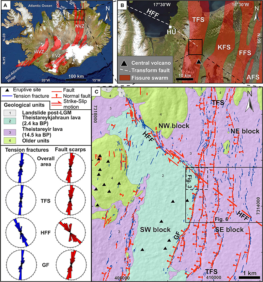
Figure 2. (A) Iceland with its volcanic zones, among which the North Volcanic Zone (NVZ), the West Volcanic Zone (WVZ), and the East Volcanic Zone (EVZ). The Tjörnes transform fault zone is composed of the Dalvik lineament (DAL), the Husavik-Flatey Fault (HFF), and the Grimsey lineament (GRL). KOR, Kolbeinsey ridge. (B) Tectonic setting of northeastern Iceland; orange stripes represent the main volcanic systems that compose the NVZ, among which the Theystareykir Fissure Swarm (TFS), one of the main objects of the present study. Black triangle shows location of Theistareykjabunga shield volcano. (C) Simplified geologic map of the study area (based on personal data and Saemundsson et al., 2012), integrated with a structural sketch map of the eastern portion of the HFF, and a major section of the TFS. Rose diagrams of faults and tension fractures are also provided.
We identified four sub-areas delimited by the intersection between the two major faults, the HFF and the GF (Tibaldi et al., 2016). As illustrated in Figure 2, the sub-areas are, respectively, located: (i) north of the HFF and west of the GF (NW block); (ii) south of the HFF and west of the GF (SW block); (iii) north of the prolongation of the HFF and east of the GF (NE block); (iv) south of the prolongation of the HFF and east of the GF (SE block).
In order to analyse at the highest level of detail the various aspects of the interconnection between a transform fault and a rift zone, we compared the structural data collected in the field at the HFF–TFS connection zone with a set of scaled experiments designed to reproduce the various possible motions under different block configurations. We used different experimental settings that involve: (i) a different number of moving blocks; (ii) the presence or absence of a ductile zone along the rift; (iii) the position of the tip point of the transform fault with respect to the rift, and (iv) the relative time distribution of the motions for the involved blocks. The goals of our study are: (i) to summarize the main geometric and kinematic characteristics of the area of connection between the HFF and the TFS; (ii) to show the different structures that may result from analog experiments focused on transcurrent-rift interactions in different settings; (iii) to compare the results in order to better understand how such interactions works and contribute to evaluating the possible prolongation of the HFF eastward beyond the TFS. The recognition of active transform faults propagating across rift zones may help to calculate the real length of these faults and related possible earthquake magnitude.
Geologic-Tectonic Framework
The North Iceland Rift coincides with the Northern Volcanic Zone (NVZ, Figure 2A) that comprises, in addition to the TFS, another four, about N–S-striking volcanic rift zones (Figure 2B), namely the Krafla (KFS), Fremrinámar (FFS), Askja (AFS), and Kverkfjöll volcanic systems (Hjartardóttir et al., 2015). Each of these systems consists of 5–20 km-wide and 60–100 km-long swarms of normal faults, eruptive and tension fractures (Figure 2C), and a main volcano (Saemundsson, 1974). Most research efforts focused on the Krafla system (e.g., Angelier et al., 1997; Acocella et al., 2000; Hjartardóttir et al., 2015), whereas the structures of the TFS were studied only recently in detail by Pasquarè Mariotto et al. (2015), Tibaldi et al. (2016), and regionally by Hjartardóttir et al. (2015).
The transform fault (HFF), which runs 25 km onshore, was first studied by Einarsson (1958) and mapped by Saemundsson (1974), and later by Opheim and Gudmundsson (1989), Gudmundsson et al. (1993), Garcia et al. (2002), Garcia and Dhont (2005), and Magnúsdóttir and Brandsdóttir (2011). It is made of en-échelon, right-stepping, and left-stepping, NW–SE dextral strike-slip fault segments (Gudmundsson et al., 1993; Gudmundsson, 2007), which separate Tertiary rocks to the north from Upper Pleistocene rocks to the south (Saemundsson, 1974; Garcia et al., 2002). This fault is marked by land surface depressions occupied by lakes (sag ponds) with an estimated component of vertical offset at the surface that amounts to 200 m (Gudmundsson et al., 1993). In addition, Tryggvason (1973) suggested that such fault can reach an overall vertical offset of as much as 1400 m, although the location of this onshore measurement remains undefined. Saemundsson (1974), based on local geology, proposed a cumulated total component of right-lateral displacement ranging from 5 to 10 km near the town of Husavik whereas, according to Young et al. (1985) it may amount to 20 km.
The HFF joins with the GF, the westernmost N–S-striking normal fault of the TFS (Gudmundsson et al., 1993) making a 54–56° angle (Figure 2C). Near the junction area, along the HFF there are several transpressional and transtensional zones localized at NW–SE fault strands with left-stepping and right-stepping geometries, respectively (Gudmundsson et al., 1993; Pasquarè Mariotto et al., 2015). Approaching the junction with the GF, the HFF main fault plane rotates gradually and splays southwards into a set of minor faults that distribute the deformation.
The study area hosts the Theistareykjabunga shield volcano (Figure 2) and its Skildingahraun lava flows, whose age has been estimated at about 14.5 ka BP (Saemundsson et al., 2012). This age is based on tephrochronology obtained from a soil covering the lava, which contains the Vedde ash tephra layer (12.0 ka BP, M.Á. Sigurgeirsson, pers. comm.). Between the Vedde ash and the Skildingahraun lava there is another soil with a basaltic tephra layer that may be correlated with the tephra (GS-2/BAS-1) found in various cores and with an age close to 14.5 ka BP (M.Á. Sigurgeirsson, pers. comm.). About 2.4 ka BP, the latest products of this eruptive center were emplaced, forming the “Theistareykjahraun” lava flows, located between the shield and the HFF (Saemundsson et al., 2012). The latest major event that occurred nearby the studied area was the rifting episode at the Krafla volcanic system from 1975 to 1984 (Bjornsson, 1985; Buck et al., 2006), resulting in several surface meter-large horizontal and vertical offsets along nearby fractures (Tryggvason, 1980, 1984, 1986). Such rifting episode was capable of inducing stress changes in the nearby fault systems within the TFZ; in particular, the 1975 dyke intrusion triggered the 1976 Köpasker earthquake as a consequence of induced Coulomb stress on the Grímsey Oblique Rift (Maccaferri et al., 2013). The rift-induced effect on the HFF resulted in: (i) an increase in the seismicity rate along the central part of the HFF, with the seismicity progressively recovering from west to east; (ii) a decrease in seismic rate along the eastern part of HFF; (iii) a modification of the way in which the system releases seismic energy (Maccaferri et al., 2013).
Field Data
The Husavik-Flatey Fault
The eastern portion of the HFF is composed of several fault segments mostly striking N125–135° (Figures 2C, 3A). These segments show right-lateral strike-slip motions with a local component of normal motions (Gudmundsson et al., 1993; Garcia and Dhont, 2005). Fault scarps face southward, suggesting transtensional kinematics with downthrow of the southern block. In two main zones, N125–135°-striking fault strands with a right-stepping geometry are linked by fault swarms striking from N340 to N00°, showing dip-slip normal kinematics (Pasquarè Mariotto et al., 2015). Several small, meter-sized pull-apart depressions are located at right-stepping overlap zones, whereas push ridges occur at left-stepping overlap zones. The surface trace of the HFF terminates against the GF through a gradual bending and a splay of the fault plane that causes the transition from an original NW–SE orientation to a N–S strike (Figures 3A,C; Gudmundsson et al., 1993).
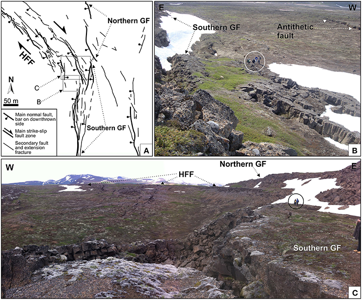
Figure 3. (A) Detailed structural sketch map of the triple junction between the Husavik-Flatey Fault (HFF) and the Theystareykir Fissure Swarm (TFS). The HFF terminates against the westernmost fault of the TFS, known as Gudfinnugja Fault (GF) through a gradual bending and a splay of the fault plane that from an original NW–SE orientation attains a N–S strike. (B) Photo of the southern GF and its antithetic normal fault, looking south. Note men in circle for scale. Location in Figure 3A. (C) Photo of the junction zone between the HFF and the southern GF, looking north. Note men in circle for scale. Location in Figure 3A.
The easternmost part of the HFF, west of the junction with the GF, offsets the lava flows of the Theistareykjabunga shield volcano dated at about 14.5 ka BP in the study area (Saemundsson et al., 2012). The amount of their surface strike-slip component of dislocation is difficult to quantify here, whereas the dip-slip component ranges from a minimum of 5 m to a maximum of 17 m. The dip-slip component increases at the easternmost termination of the HFF, in correspondence of the bending and splay of the main fault plane. The dip-slip displacements completely replace transcurrent ones when the splay fault strands attain the about N–S strike of the GF. We noticed that the easternmost fault strand shows the larger offset; hence, we can define this zone as an extensional leading imbricate fan.
The Theystareykir Fissure Swarm (TFS)
The TFS has a total length of 34 km; it is 8-km-wide in the study area south of the junction with the HFF, and narrows to < 3 km north of the junction. In the study area, normal faults and tension fractures strike N350–N20°, with an average of N00°. Several individual faults that characterize the TFS are spaced from 0.2 to 1 km apart from each other. Most individual fault segments gradually fade out and are replaced by tension fractures with the same orientation as the faults (Figure 2C). Other tension fractures are located far away from the faults.
Besides this general pattern, very detailed field surveys showed that, in correspondence of the possible prolongation of the HFF into the TFS, rift fractures tend to rotate (Figures 2C, 4). Here, faults strike N00 to N22° and N125 to N180°, as far as about 0.5 km from the theoretical prolongation of the HFF (Figure 4A). This means that along this strip coinciding with the possible prolongation of the HFF, there are structures with the same orientation as the HFF. At greater distances from the HFF prolongation, fault strikes tend to be oriented about N–S and, more exactly, they strike mostly N160–180° and N00–40°. In other words, structures with the same orientation as the HFF are missing in the TFS at distances >0.5 km both north and south of the prolongation of the HFF, whereas along the HFF prolongation, a generalized anticlockwise rotation of the TFS structures can be clearly observed. An identical situation can be observed also in regard to the strike of tension fractures, as shown in Figure 4B. Also the opening directions of tension fractures show a homogenous distribution in the range N65–120° as far as about 0.5 km from the HFF prolongation, whereas at shorter distances the range is wider, from N25 to N125° (Figure 4C). It is worth mentioning that about 50% of the tension fractures show opening directions that are oblique with respect to the fracture strike (Figure 4D), indicating a right-lateral component.
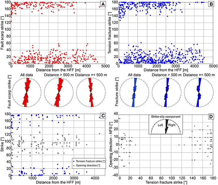
Figure 4. Structural data measured along the TFS. (A) Plot of the distribution of fault strikes measured in the field and on high-resolution satellite images (total = 434; Y axis), vs. the distance from the HFF prolongation in meters (X axis). Such distance is defined as the minimum distance from the surface projection of the fault (e.g., Bindi et al., 2011). Below the graph, rose diagrams with fault strike distribution are provided. (B) Plot of distribution of tension fracture strike measured in the field and on high-resolution satellite images (total = 722) (Y axis), vs. distance from the HFF prolongation in meters (X axis). Below the graph, rose diagrams with tension fracture strike distribution are provided. (C) Plot of distribution of opening directions measured in the field (total = 141) along tension fractures, vs. distance from the HFF prolongation in meters (X axis). (D) Graph of tension fracture strikes measured in the field (total = 141; Y axis), vs. the angle between the opening directions and the normal to the fracture strike (NFS). Positive values indicate a right-lateral component of the opening direction, negative values show a left-lateral component.
As far as faults are concerned, Tibaldi et al. (2016) recognized 10 fault zones in the study area (Figure 2). The westernmost structure is the GF, which is 5.7 km long and whose strike is mainly N00–10° but in detail it ranges between N350 and N20°. Although in previous works the GF was regarded as a single fault continuously running from south to north of the HFF tip, we document that it is actually composed of a series of discrete fault strands. Starting from the north, there is a NNE-striking tension fracture that gradually transitions into a fault scarp. The scarp faces to the west and is initially 1–3 m high, gradually increasing to 25 ± 2 m and then decreasing to 15 ± 2 m near the junction with the HFF (Figure 5). At a distance of 21 m from the junction, the fault scarp dies out and a fault bridge separates it from the GF scarp located south of the junction. At the junction with the HFF, the southern GF has a N160° strike and shows a dip-slip component of about 25 m. Farther south, the offset increases to the maximum value of 33 ± 2 m and locally there are antithetic faults creating a narrow asymmetric graben (e.g., Figure 3B). North of the junction, there are 14.5 ka old lavas at both fault sides. South of the junction, 14.5 ka old lavas crop out on the eastern block and 2.4 ka old lavas are observed on the western block (hanging wall). This indicates that the measured offsets south of the junction are minimum because part of the real total offset has been hidden by the younger lavas onlapping the fault scarp. This also means that the difference in offset along the GF is even larger between north and south of the junction with the HFF.
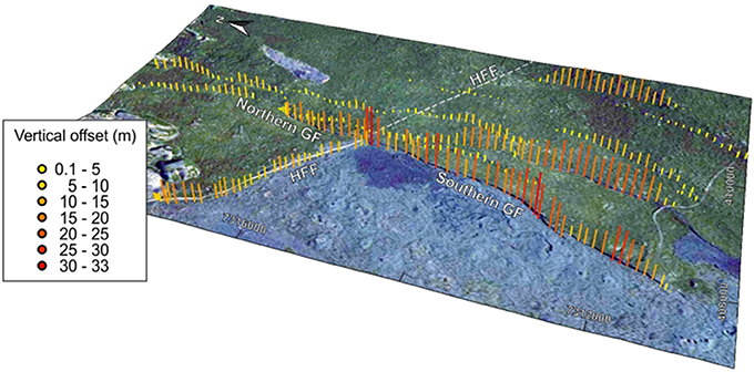
Figure 5. Bar graphs summarizing the offsets cumulated along all the faults located north of the possible prolongation of the HFF with respect to those located south. The graph clearly indicates that those located to the south have much larger offsets.
All the other single fault segments of the TFS range in length from 10 to 1339 m. The scarps always face to the west, indicating gradual downthrowing in the same direction. These faults affect the same lavas dated at 14.5 ka BP, which have the same horizontal attitude, and thus the offsets and geometry of the faults can be directly compared with each other. The offsets measured systematically by Tibaldi et al. (2016) indicate that the faults located north of the possible prolongation of the HFF have smaller offsets than those located to the south (Figure 5). The same authors also discovered that the faults of the TFS change their geometry along a strip corresponding to the possible prolongation of the HFF toward the south-east (Figure 6). To highlight this, they plotted only the segments of tension fractures and faults of the TFS that do not have the typical N00 to N20° orientation. These segments depict a corridor where the fractures strike exactly as the easternmost strands of the HFF west of the junction with the GF (N330–N340°), with an overall pattern that is consistent with the earlier stages of development of a transtensional fault system (Harding et al., 1985; Clifton et al., 2000; Agostini et al., 2009).
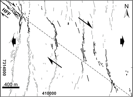
Figure 6. Plot of the segments of tension fractures and faults of the TFS that do not have the typical N00 to N20° orientation. These segments depict a corridor where the fractures strike exactly as the easternmost strands of the HFF (N330–N340°), with an overall pattern that is consistent with the earlier stages of development of a transtensional right-lateral fault system (modified after Tibaldi et al., 2016).
Experimental Methodology
Experimental Apparatus
The experimental apparatus consists of a rectangular box (70 × 65 × 10 cm) confined by three moveable and one fixed walls at the shorter sides, and two fixed walls at the longer sides (Figure 7A). The three moveable walls are fixed to the underlying metal plates that mimic the tectonic blocks; three of such plates are moveable (moving metal plate NW, SW, SE), and one is fixed (fixed metal plate NE) to the basal wood table (Figure 7A). Three of them are anchored to their “moving plate system,” capable of moving the plates very slowly (reaching high precision) and orthogonally to the sidewalls (Figures 7A,B), simulating the E–W opening direction (extensional stresses) in the studied area, that has been acting for the last 14.5 ka (Pasquarè Mariotto et al., 2015); such opening direction is also supported by GPS data from Jouanne et al. (2006).
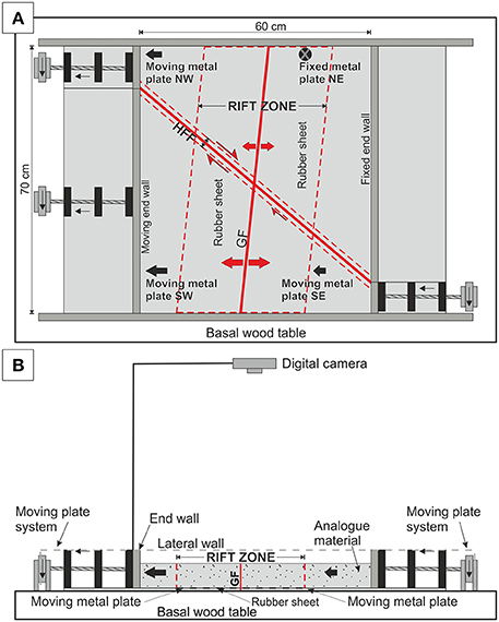
Figure 7. Sketch of the experiment apparatus: above in plan view and below in section view. (A) Three out of four plates can move together or singularly. (B) The angle α indicates the amount of transtension. The arrows indicate the vs. of plate movement and their dimension is proportional to the relative slip rate.
The edge effect due to the sharp termination of the plate has been minimized by choosing the thinnest possible rigid aluminum plate, with a thickness of 0.24 mm. The geometry of the metal plates has been tailored in order to mimic as much as possible the fault geometry studied in the field. Based on recently collected field data (e.g., Pasquarè Mariotto et al., 2015), the TFS is assumed as trending N06° based on its overall geometry, as well as on the first westward normal fault of the TFS (the GF); the eastern part of the HFF, close to the triple junction, is assumed as N130°-striking (Figure 2C). A shown in Figure 7A, the GF and the HFF are highlighted with a red line and represent the limits of the four plates.
Scaling Procedure
Analog experiments were geometrically and dynamically scaled (e.g., Holohan et al., 2005; Norini et al., 2008 Ruch et al., 2012). Material properties and forces in the experiments should comply with the principle of geometric and dynamic similarity (Hubbert, 1951) and operate according to a consistent length ratio (h*) determined by h* = hModel/hNature (Merle, 2015). For the geometric scaling of our models we chose a scaling ratio given by l* = lModel/lNature, = 1 × 10⁻⁴, such that 1 cm in the model scales to 100 m in nature. In agreement with this scaling, the length of the GF in the model is 60 cm, corresponding to its actual length (about 6 km) in nature (Pasquarè Mariotto et al., 2015). The dynamic scaling factor (stress ratio, σ* = σModel/σNature) is calculated from the equation σ* = ρ*g*l*. As the density of analog materials is smaller than that of natural rocks by a factor of ~2 (i.e., density ratio—ρ* = 0.5), and gravitational acceleration is the same in both model and nature (i.e., gravity ratio—g* = 1), the required stress ratio for a geometric scaling factor of 10−4 is σ* = 5 × 10⁻⁵. As the cohesion of natural rocks lies in the range 105–107 Pa (Hoshino et al., 1972 Glicken et al., 1980), a suitable cohesion for the analog material needs to be in the range 5–500 Pa. Higher values of 107 Pa, in nature, are representative of small laboratory samples (Schultz, 1996) or intact rock (Handin, 1966; Jaeger and Cook, 1971).
In our experiments we used a mixture of two end-member analog materials, i.e., sifted sand and wheat flour, with the purpose of simulating brittle deformation in the upper crust (e.g., Walter and Troll, 2001; Holohan et al., 2005; Tibaldi et al., 2008; Acocella et al., 2013; Tortini et al., 2014). The density range for natural rocks is approximately 2000–3300 kg/m3, with most rocks (granites, basalts, hard limestones, etc.) lying between 2600 and 3000 kg/m3 (Goodman, 1989). Therefore, we used a mixture of wheat flour and sifted sand, both 50% in volume: (i) the dry, sifted sand is characterized by a grain size of 200÷ 350 μm, a bulk volume of 1470 kg/m3 and a low cohesion (e.g., 30–40 Pa—Walter and Troll, 2001); (ii) the wheat flour has a bulk density of 700 kg/m3 and a cohesion of 330 Pa (Krantz, 1991); (iii) our mixture has a density of 1215 kg/ m3, a measured ϕ of 41° and a cohesion surely between the range 5–500 Pa, in order to reach a scaled value close to natural rocks (106 Pa; e.g., density ratio and cohesion range).
According to the Bukingam-∏theorem, or pi Theorem (Tibaldi, 1995; Galland et al., 2014; Merle, 2015, and references therein), seven variables minus three dimensions, equal to four independent dimensionless numbers (Table 1) are needed to maintain a value as close as possible between the field and the experimental system, in order to warrant similarity. Time was not scaled in our experiments, because the brittle behavior of sand and other Mohr–Coulomb materials is generally regarded as independent of the strain rate (Holohan et al., 2005; Merle, 2015).
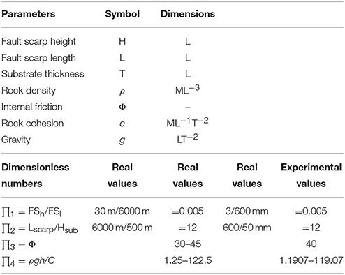
Table 1. List of parameters and dimensionless numbers used in this work.
The first and second dimensionless numbers account for the geometric ratio of the system (e.g., Merle, 2015):
In nature, the GF is 6-km-long and has a maximum offset of about 30 m; therefore, at the scale of the experiment, it has a length of 60 cm and a vertical offset of 3 mm.
We consider a crust portion of about 500 m; hence, at the scale of the experiment, the GF has a length of 60 cm and the substratum thickness is about 5 cm.
The third dimensionless number accounts for the brittle behavior of the analog material and the substratum. It is the angle of internal friction:
Angles of internal friction of the sand (Φsand = ~33°) and the flour (ϕwheatflour = ~43°) closely resemble those in natural rocks (30–40°, Byerlee, 1978) as well as in volcanic rocks (Φrocks = 30–45°, Walter and Troll, 2001). Our analog material has an Φ = ~41°.
The fourth and last dimensionless number is the ratio between the gravity stress and the cohesion (Merle, 2015):
In our experiments, h corresponds to the thickness of the substratum (500 m scaled to 5 cm in the model) and ∏4 ranges from 1.19 to 119, with a cohesion for the analog material in the range 5–500 Pa; we used an analog material with a cohesion of about 150 Pa. An average density for natural rocks is about 2500 kg/m3, but the range for sedimentary and magmatic rocks is from 2300 to 2900 kg/m3 and their typical cohesion is between 105 and 107 Pa (Hoshino et al., 1972; Glicken et al., 1980). Thus, overall values of ∏4 in nature range from 1.22 to 122, with a fixed density of 2500 kg/m3 and varying the cohesion (105 and 107 Pa). Hence, the values of ∏4 in the experiments correspond to those in natural systems. So the model has been geometrically and dynamically correctly scaled.
Quantification of Fault Slip and Experiment Set-Up
We conducted a series of analog modeling experiments by simulating the movement of the NW, SW, and SE blocks (Figure 2) with different combinations, always imparting an amount of westing movement based on GPS data, for the E–W opening direction (or west spreading), derived from Jouanne et al. (2006). Based on the published GPS measurements, we considered a westing movement of about 10 mm/yr for the NW block, 15 mm/yr for the SW block, and 6 mm/yr for the SE block. Since faults and tension fractures (Figure 2) affect the 14.5 ka-old lavas, a maximum westing movement of 145 m for the NW block, 217 for the SW block, and 87 m for the SE block has been reconstructed. At the scale of the model (10−4), the above values correspond to about 14.5, 21.7, and 8.7 mm, respectively. Consequently, the NW block moves about 1.5 times faster than the SE one, and the SW block moves about 2.5 times faster than the SE one. Such configuration has been reproduced in the models, firstly by moving only the SW block, then the NW and the SW blocks, and then by moving contemporaneously all three blocks at the scaled westing velocity. Finally, a series of experiments has been conducted by creating first the rift zone and then the transform fault across it. At each step, the SE block has moved to the east of 0.5 mm, the NW one has moved of 0.75 mm and the SW one has moved of 1.25 mm, corresponding to 5, 7.5, and 12.5 m in nature.
By taking the NE block as fixed: (i) we reproduced extension in the northern part of the TFS by moving the NW block toward the west, (ii) as well as we reproduced the possible prolongation of the HFF across the TFS by moving also the SE block toward the west (Figure 7). The extension in the southern part of the TFS as well as the movement along the HFF was reproduced by moving the SW block at a rate higher than the NE and SE blocks, consistently with field and GPS data. Such data also suggest that the extension amount across the southern part of the TFS is greater than that going on in the northern TFS (roughly estimated in about 8–10 and 3–5 mm/yr, respectively); such setting has been mimicked in our analog experiments by choosing this block configuration.
The geological-structural evolution of the study area has been characterized by different episodes of lava emplacement and faulting events. In order to develop experiments which are as much as possible similar to reality, we simulated the evolution of the study area by creating a deposit of the granular mixture above the metal plates, then inducing fractures along the transform fault zone and the rift zone by deforming the granular mixture, then filling structural depressions and the adjoining areas with new granular material and then deforming it again.
Furthermore, we ran two different sets of experiments, the first with no ductile connection among the plates (the rubber sheet), and the second with a ductile connection as large as the TFS. During the experiments without the ductile connection we focused on the surface effect of propagation of a pre-existing deeper fracture. In the second series of experiments we added a 30-cm-wide rubber strip in order to: (i) locate the rift zone area (e.g., Morley, 1999); (ii) simulate a broad zone of extension (rift zone) between the two plates (McClay, 1990; Tron and Brun, 1991; McClay and White, 1995). In our model, the rubber sheet has a trend of N06°, similar to the TFS overall orientation. The TFS width (e.g., Figure 2) has been scaled to the model (Figure 7A). The rubber sheet has been centered over the edge of the metal plate and has been securely attached (e.g., Clifton et al., 2000), so as to restrict extension to the central part of the model (e.g., McClay, 1990). Consequently, the angle between the zone of rifting and the extension direction was controlled by the orientation of the rubber sheet (e.g., McClay and White, 1995). Furthermore, we added a 4-cm-wide rubber strip along the HFF.
Assumptions and Limitations
Our box hosting the granular mixture was made with dimensions larger than those necessary for highlighting the actual area of interest near the transform fault—rift junction. This option was chosen in order to avoid side effects that might perturb the geometry and kinematics of the experiments. This correct procedure and scaling is testified to by the observation that, in all experiments, the measured surface deformation amounts, as well as the geometry and kinematics, do not vary at considerable distance form the area of interest, and perturbations do occur only at few-cm wide strips near the boundary walls. This suggests that boundary effects due to the confinement of the granular mixture within the box may be neglected.
In our models we simulated the pre-existence of fractures along the transform fault zone and the rift zone by deforming the 4 cm-thick granular mixture, then filling structural depressions and the adjoining areas with a 1 cm-thick layer of new granular material and then deforming it again. This was aimed at mimicking the evolution of the studied area in the most realistic way, keeping into account the existence of new lava flows covering the studied area over time (e.g., Saemundsson et al., 2012). However, we need to acknowledge that the interior of the resulting blocks is characterized by isotropic conditions: any pre-existing fracture and layering within the blocks that could affect the resulting deformation pattern is not included and is beyond the scope of the study.
During the experiments based on the set-up without the ductile connection between the plates (the rubber strip), as already introduced before, the edge effect due to the sharp termination of the plate has been minimized by choosing the thinnest possible aluminum plate (0.24 mm).
In regard to the influence of igneous intrusions on the formation of the structures in the studied area, we are aware that tension fracture opening can occur along a rift also as a consequence of magmatic pressure (Gudmundsson, 1987a,b, 1995; Opheim and Gudmundsson, 1989; Trippanera et al., 2014, 2015; Sigmundsson et al., 2015). In fact, it is well-known that, at the tip of an advancing dyke, tensile stresses can increase due to magma injection (Rubin and Pollard, 1988; Rubin, 1992) and exceed the Coulomb failure threshold, triggering earthquakes in the brittle crust (Brandsdóttir and Einarsson, 1979; Einarsson and Brandsdóttir, 1980; Feigl et al., 2000; Cattin et al., 2005). The effects of magmatic pressure at an advancing dyke have already been explored in several papers by field data, numerical modeling, and analog experiments (review in Rivalta et al., 2015, and reference therein). The present paper, instead, is mainly devoted to understanding the overall geometry and kinematics of the structures, and assessing the relative development of the transform and rift zones. Nevertheless, a mention of the implications of the possible role played by dykes in the study area is provided in the discussion section. It is worth mentioning that the strain rate may vary considerably in time, because intrusions can produce meter-scale deformation in few days (e.g., Metzger et al., 2011).
Finally, thermal effects are not included in our experiments. Although this is a common limitation of most analog experiments, we stress also the fact that possible differences in the thermal flux below the HFF respect to the TFS are not known in the study area and it would have been difficult to quantify them anyway. An anomalous heat flux should be present further south, where the Þeistareykjavirkjun geothermal plant is under construction.
Experiment Results
Here, we describe only a selection of the total of 20 experiments we have conducted, and will dedicate another paper to the full description of all models. The examples reported below refer to the models that are more relevant to the discussion of the development of different structures around the HFF-rift junction. We will present experiments with a more and more complex set-up in order to assess the role played by the relative movement of each tectonic block in creating the final general structural pattern observed in the field (experiments 1, 2, and 3). This was done also in view of the previously suggested different models of transform fault termination. Experiment 4 has been carried out to simulate a broader zone of extension, and finally experiment 5 was conceived to verify the relative timing of tectonic events.
Under the set-up of the first series of experiments (no ductile connection among the plates, Table 2), experiment 1 was run by moving only the plate south of the HFF (SW plate in Figure 7) toward the west with respect to the other fixed plates, mimicking a two-plate configuration (Figure 8A). After gradual increments in motion, we added another 1 cm-thick layer of granular material and then applied the successive deformation in gradual steps. In Figure 8A we show the step with an extensional cumulated deformation of 7.5 mm that corresponds to the slip cumulated by the “Theistareykjahraun” lavas at a rate of 6 mm/yr during the last 12.5 ka (Table 2). The movement created a series of faults all around the plate boundaries (Figure 8B); most notably, a series of en-échelon, strike-slip right-lateral faults with a left-stepping geometry formed, which show also a subordinate normal component. With reference to the north coinciding with the moving end-wall of the experiment box (Figure 7), these faults strike mostly N130–140° in the central and western part of this fault zone. Toward the east, the faults gradually bend attaining a N–S orientation. The transcurrent kinematics is gradually replaced by normal displacements with the formation of scarps facing both eastward and westward. The normal faults are accompanied by the development of parallel extension fractures.
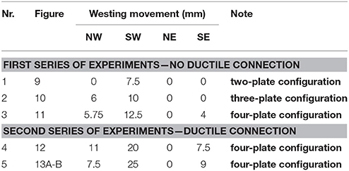
Table 2. List of experiments done in the present work.
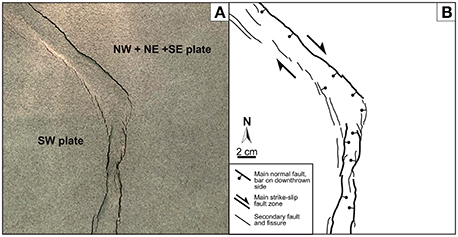
Figure 8. (A) Photo of the experiment 1, made with only the SW plate moving westward, and the other three plates fixed. (B) Sketch of the photo with indication of the main and secondary faults and extensional fractures. Note the development of the transform fault (HFF) with a right-lateral transtensional kinematics and of the southern GF with normal motions. This one-plate kinematics does not account for the other structures found in the field.
Experiment 2 (Table 2) uses a three-plate configuration (Figure 9A) obtained by moving contemporaneously the plates south and north of the HFF (SW and NW plates in Figure 7) toward the west at different velocities, and keeping the two plates east of the TFS locked. Also in this case, after the various gradual increments in motion, we added another layer of granular material; then we gradually imposed a successive westward motion totalling 10 mm at the SW plate, and a total westward motion of 6 mm to the NW plate. The plate movements resulted in a zone of en-échelon, normal right-lateral faults with a left-stepping geometry like in the previous set of experiments. With the set-up of experiment 2 (Figure 9), anyway, we can see the development of the rift zone north and south of the junction with the transcurrent fault zone. It is worth observing the greater number of normal faults and higher normal offsets south of the junction, consistent with the larger westward displacement of the plate located south of the HFF. All faults and extensional fractures developed along the rift have the same dominant orientation, although locally they show a gentle zig-zag pattern. In correspondence to the junction between the transcurrent fault and the rift, there is no offset of the rift faults but rather a complex zone with the formation of rhomboidal structures in plan view. There is no gradual bending of the transcurrent fault near the junction, but instead this fault maintains a rectilinear geometry until it ends in correspondence of the eastern-most fault of the rift.
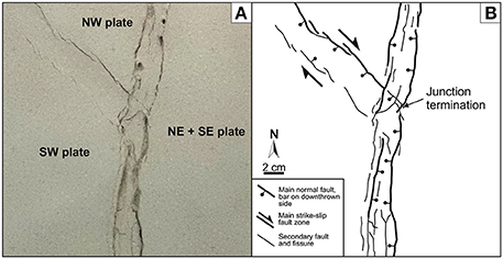
Figure 9. (A) Photo of the experiment 2, made with only the NW and SW plates moving westward, and the other two plates fixed. (B) Sketch of the photo with indication of the main and secondary faults and extensional fractures. Note the development of the transform fault (HFF) with a right-lateral transtensional kinematics and of the complete GF both north and south of the junction (indicated by the arrow). This two-plate kinematics does not account for the interruption of the GF north of the junction and its bending, as well as of the other field structures located further to the east.
Experiment 3 (Table 2 and Figure 10) is based on a four-plate configuration obtained by moving contemporaneously, with differential increments, the plates south, and north of the HFF toward the west, by moving at a lower rate toward the west the plate south-east of the TFS (SE plate) and keeping the plate north-east of the TFS (NE plate) locked. The procedure followed the same steps described for the previous experiments. The cumulated westward motion of the SW plate is 12.5 mm, for the NW plate it is 5.75 mm, and the total cumulated offset of the SE plate toward the west is 4 mm (Table 2). The plate movements induced the formation of the normal right-lateral faults between the NW and SW plates, which show a N130–140° strike in the central and western part of the transtension zone. At the eastern part instead, there is a gradual anticlockwise bending of these faults that attain a N–S strike in correspondence of the junction with the rift. It is also worth highlighting the formation of three main fault strands at the eastern termination of the right-lateral transtension zone, all affected by a larger component of normal motions with respect to the more western segments. This fault zone is connected with the southern segment of the rift zone, whereas there is no connection with the northern segment. The rift is characterized by a discontinuous development of faults and extension fractures, and it is particularly worth highlighting the gradual anticlockwise bending of the southern termination of the northern segment of the rift faults (arrow in Figure 10B). Southeast of the junction, a series of en-échelon left-stepping fractures developed. These structures lye above the boundary between the NE and the SE plate, whose differential movements mimicked a dextral transtensional zone.
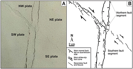
Figure 10. (A) Photo of the experiment 3, conducted by moving westwards at differential velocities and amount the NW, SW, and SE plates, and keeping the NE plate fixed. (B) Sketch of the photo with indication of the main and secondary faults and extensional fractures. Note the strong similarity with the real field data of the same area, as shown in Figure 3. The HFF gradually bends toward the south near the junction with the GF. North of it, the northern fault segment bends toward the SE. Southeast of the junction, a series of en-échelon, left-stepping fractures developed, as observed in the field.
A second set of experiments was run by adding a ductile connection among the plates, as described above. This 30-cm-wide rubber strip was used to locate the rift zone area (e.g., Morley, 1999) and to simulate a broad zone of extension (rift zone) between the two plates (McClay, 1990; Tron and Brun, 1991; McClay and White, 1995). Experiment 4 was conducted under the same set-up described for experiment 3—i.e., a four-plate configuration, and the metal plates were moved up to a similar cumulated total displacement as in the previous set-up (Table 2). It is possible to notice that the four-plate configuration with the ductile connection results in a diffuse zone of strain in correspondence of the rift zone (Figure 11), giving rise to a wider rift than that in the previous experiments. The rift zone is characterized by a series of anticlockwise-rotated fractures in correspondence of the boundary between the NE and SE plate. West of the junction, the normal right-lateral fault zone developed.
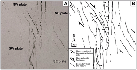
Figure 11. (A) Photo of the experiment 4, made by moving westwards at differential velocities and amount the NW, SW, and SE plates, and keeping the NE plate fixed, plus a diffuse zone of strain across the whole rift (TFS). (B) Sketch of the photo with indication of the main and secondary faults and extensional fractures. In this case several other faults and extensional fractures developed east of the GF, mimicking the overall structure of the real TFS. The change in strike of the TFS structures southeast of the HFF–GF junction is related to the presence of a NW–SE right-lateral shear zone below the rift, and supports our interpretation of the HFF prolongation.
Experiment 5 was conducted again with a four-plate configuration and the ductile lower zone but, in this case, we first moved the NW and SW plates, creating the rift, and later on we moved only the SW and SE plates inducing the HFF also across the rift (Figures 12A,B). This experiment, thus, mimics the recent propagation of the HFF toward the southeast, across an already developed rift zone (TFS). The metal plates were moved up to a total slip of 7.5 mm (NW plate), 25 mm (SW plate), and 9 mm (SE plate; Table 2). We can observe that this set-up produces a clockwise rotation and some offset of the rift faults. Most fault strands along the prolongation of the shear zone through the rift attain a N10 to N30° strike, which does not correspond to the field geometry of the actual TFS here. As a comparison, Figures 12C,D show another experiment done as the set-up of experiment 4 with the simultaneous development of both the rift and the shear zone. Note that, in this case, like in Figure 11 of experiment 4, the fractures along the prosecution of the shear zone across the rift strike more NNW–SSE, and thus they have a different geometry from the structures developed in experiment 5.
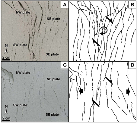
Figure 12. Photos of the analog experiments and sketch of the resulting fracture field under different time relationships between the development of the rift zone (TFS) and the SE-ward prolongation of the transform fault (HFF). In (A) and (B; experiment 5) we observe the geometry of the tension fractures and faults obtained first by forming the rift zone and then by inducing the HFF right-lateral shear zone across the rift. (C) and (D). represent, instead, the geometry when the rift zone develops contemporaneously to the right-lateral shear zone across it (i.e., the HFF prolongation). Note that case (C,D). is in better agreement with the field data.
Discussion
The field data here presented allow to better define the geometric and kinematic characteristics of the studied faults, whereas the integration with analog models enables to constrain the space and time relations between the transform HFF and the TFS rift zone. The outcomes resulting from this combined approach will be discussed in the following sections.
General Features Based on Field Data
Starting with the HFF, this major fault shows a complex geometry and kinematics toward the junction with the TFS. With respect to the classical models of terminations of transform faults (Figure 1), it appears that the HFF has an intermediate character between several end-members; the fault ends via a branching, toward the south, of the main fault plane into various splays, which gradually bend (Figure 13). They are characterized by a normal component of movement that increases toward the east, and thus the overall geometry and kinematics resemble the model of Figure 1B in the form of a leading extensional imbricate fan. The leading (i.e., easternmost) splay fault merges with the GF, thus recalling also the model of Figure 1C. However, the possible prolongation of the HFF toward the southeast, across the TFS, is more similar to the model of Figure 1D, with the transform fault that terminates gradually in correspondence of a through-going normal fault system. These data, apart from improving the knowledge about this Icelandic zone, also indicate that the detail that can be obtained in the field enables to define the geometric setting of a transform-rift junction, which is indeed much more complex than those that can be reconstructed by means of offshore studies.
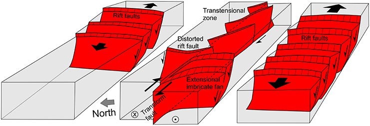
Figure 13. The model of transform fault termination suggested by our data: The main transcurrent fault plane gradually bends and splays giving rise to a releasing imbricate fan. Further east, the fault interacts within the rift zone producing en-échelon fissures and normal faults rotated anticlockwise with respect to the N–S rift structures. The size of the half arrows (along the transform fault) is proportional to the amount of strike-slip motions; the size of the full arrows is proportional to the extension amount in the rift.
The configuration of model of Figure 1D is associated with a three-plate configuration, which corresponds to: (i) the tectonic bock located south of the outcropping HFF, (ii) the block located north of it, and (iii) the block located east of the TFS. The latter corresponds to a zone of diffuse deformation as indicated by the presence of several extensional fractures and 10 major, normal faults, all of which are striking mostly around a N–S direction. The extension directions measured in the field at the TFS are mostly from N90 to N100°, and in the SW block (located south of the outcropping HFF) the dominant extension axes are N100–110° (Tibaldi et al., 2016). These axes are consistent with the component of extension recognized in the field along the HFF, which thus can be classified as a transtensional fault, at least along its eastern termination. This range of values is consistent with the GPS vectors measured in the same area by Jouanne et al. (2006) and Metzger et al. (2013).
We wish to underscore the lack of a direct connection between the GF north and south of the junction with the HFF. The detailed field data of Figure 6 shows that the segment of the GF north of the junction bends toward the SE and terminates without connecting with the GF south of the junction. The apparent offset between these two segments of the GF is about 20 m in a strike-slip right-lateral sense (see Figure 3).
All these observations represent also a robust dataset for planning the analog experiments that we conducted to better define the structural evolution of the interaction zone between the HFF and the TFS. From the field data alone, in fact, it is difficult to fully understand how the system works. Several different hypotheses can be proposed, with particular regard to the phases of development of the different faults. For our analog experiments we used different set-ups to reproduce the development of the HFF with respect to the TFS, as discussed below.
Prolongation of the HFF by Field Evidence and Analog Modeling
Previous research suggested that the HFF ends at the junction with the westernmost fault of the TFS, represented by the GF (Gudmundsson et al., 1993; Magnúsdóttir and Brandsdóttir, 2011). This observation is convincing if one looks at the surface trace of the already known HFF: this fault zone, in fact, is composed of a series of closely spaced fault scarps that mostly strike N130–140° and than bend into the GF, without any evident prolongation east of the junction. More recently, a possible subsurface prolongation of the HFF toward the southeast has been proposed, on the basis of earthquake and fracture distribution near the Krafla fissure swarm (Hjartardóttir et al., 2012). In correspondence of the TFS, Tibaldi et al. (2016) suggested the possible prolongation of the HFF southeast of the junction based on substantial field evidence, including changes in the TFS structures north of the prolongation of the HFF, with a decrease in: (i) the width of the TFS; (ii) the number of faults; (iii) the fault offset values. Moreover, iv) along the prolongation of the HFF there is a generalized anticlockwise rotation of the TFS structures (Figures 4, 6). We hypothesize that this evidence can be reconciled in terms a four-plate configuration given by the tectonic blocks located north and south of the already known trace of the HFF (NW and SW blocks in Figure 2), plus a third tectonic block in correspondence of the southeastern TFS (SE block in Figure 2) and a fourth tectonic block in the northeastern sector of the TFS (NE block in Figure 2). In order to test whether this block configuration might produce the observed structures, we have run a series of analog experiments with different set-ups and compared our experimental outcomes with field data.
Experiment 1 (Figure 8) created a series of major normal faults with angles of 50–60° with respect to the right-lateral strike-slip fault. This range matches the 50–60° angles measured in the field between the N130° and 140° segments of the HFF with respect to the GF. Anyway, this configuration, in which we moved only the plate south of the HFF, does not reproduce all the features of the studied area, and especially the normal fault segments present north and east of the junction.
The set-up of experiment 2 (Figure 9) created a series of major normal faults with an angle of 50–60° with respect to the right-lateral strike-slip fault, both north and south of the junction. This configuration reproduces correctly the HFF, the GF and its connection with the HFF, as well as the other, N–S-striking normal faults and extensional fractures, located north of the junction. In particular, the larger westward displacement of the plate located south of the HFF with respect to the plate located north of it, produced a greater amount of normal faults and larger normal offsets south of the junction. This is exactly what we found along the western sector of the TFS. By increasing the total motion of these two plates, we obtained an enlargement of the offsets of the faults along the rift zone. Anyway, the faults and extensional fractures developed along the rift have all the same orientation, and thus this set-up of the experiments is not able to mimic the variation in the geometry of the fractures of the TFS near the HFF–GF junction, which is characterized by the bending of the northern segment of the GF, and does not reproduce the fractures located along the possible prolongation of the HFF.
Experiment 3 (Figure 10) induced: right-lateral transtension along the HFF, the junction with the GF, larger normal motions south of the junction, the bending of the northern segment of the GF, and en-échelon fractures south-east of the junction. We wish to stress that only this plate configuration created an anticlockwise rotation of the fractures of the GF both north and south of the HFF–GF junction. If we compare the structural pattern around the junction in experiment 3 (Figure 10) with the field data for the same area shown in Figure 6, we can observe the strong similarity. It is also possible to notice, in the experiment, the development of a series of left-stepping, en-échelon structures southeast of the junction. These structures formed above the boundary between the NE (fixed) plate and the SE plate, which was moved very slowly westwards, hence mimicking a dextral, transtensional zone.
In experiment 4 (Figure 11), a wide rift zone fully develops and a more complex geometry occurs along an area that corresponds to the boundary between the underlying NE and SE plates, represented by an anticlockwise rotation of the TFS structures. This re-orientation of the rift zone fractures has been induced by the local orientation of the σ3 linked to the right-lateral shear zone, and mimics the geometries found in the field at the TFS along the prolongation of the HFF, as shown in Figure 6 and resumed in Figure 13. Based on experiments 3 and 4 (Figures 10, 11), we argue that the four-plate configuration is the one that fits best with field data, and thus our analog experiments confirm the hypothesis proposed by Tibaldi et al. (2016) regarding the prolongation of the HFF across the TFS southeast of the junction with the GF. Our work indicates that such prolongation may amount to, at least, 3 km into the TFS.
In regard to the relative time of propagation of the HFF across the TFS, experiment 5 (Figures 12A,B) indicates that, in the case of the HFF propagation toward the southeast after the development of the TFS, the rift fractures tend to rotate in a clockwise direction, and locally they are right-laterally offset, instead of assuming a NNW–SSE strike (anticlockwise respect to the dominant N–S orientation of the rift fractures) as observed in the experimental set-up of Figures 10, 11, 12C,D and, especially, in the field. In our experiments, only in the case of contemporaneous motions between the rift and the right-lateral shear zone across it, it has been possible to reproduce all the features seen in the field. As a consequence, the faults and tension fractures of the TFS must have developed at the same time as the right-lateral motions along the southeastern prolongation of the HFF.
The relative motions among the various moving plates in the analog experiments are such that the amount of the right-lateral strike-slip movement between the NE and SE plate is much smaller than the strike-slip movement between the NW and SW plate. This implies that, in the experiments, the segment of the transform fault east of the junction is much less developed at the surface than the transform fault segment west of the junction. This is consistent with the geometry of the structures that developed during the experiments. West of the junction, in fact, where the cumulated offset is larger, the transform fault zone is expressed by a series of long en-échelon fracture segments oblique to the main fault zone, and a few segments parallel to the fault zone, most of which are interconnected. This fault architecture corresponds to the Riedel (R) and P structures that form during the development of a shear zone, following the classical nomenclature of Tchalenko (1970). East of the junction instead, the transform fault geometry is given by a series of shorter en-échelon fractures at higher angle respect to the general deformation zone. This architecture recalls the Riedel' (R') structures that form in the very early stage of a transtensional zone (Sylvester, 1988; Agostini et al., 2009). Moreover, we need to keep into account the role played by the combination of transform faulting and rifting, evidenced by both field data and analog modeling. The same two patterns of structures are present in the field at the two sides of the junction HFF-rift. Since the lava deposits east and west of the junction have the same age (14.5 ka BP, Saemundsson et al., 2012), we can conclude that two fracture patterns correspond to two stages of development of the HFF; the segment east of the junction is less developed because here the HFF moves at a much lower rate than west of the junction, at least from the perspective of a Holocene time window.
From a more general perspective, our results contribute to improving previous models on transform fault termination. The field and experimental data suggest that, over a given time window, a transform fault might end through a decrease in the slip rate across the rift, partitioning its motion in correspondence of more than one companion structure (Figure 13). But our model also implies that a transform fault tip may be unstable with time and that the fault may propagate across the rift; therefore, fault length can increase with time. Another possibility is that the horizontal position of the transform fault tip is stable with time, but its location cannot be recognized simply because it is covered by lava deposits which are younger than the latest fault motion. In this case, the next fault motion will occur via an upward propagation of the fault plane close to the tip.
Role of Magma Intrusions
In the previous sections we have contributed to explaining the geometry and kinematics of the structures at the zone of intersection between the HFF and the TFS, with a very good fit between field and analog data under a four-plate configuration. Considering the forces responsible for this deformation field, it is necessary to take into account also the role of igneous intrusions.
As classically accepted, the magmatic pressure from intruding dykes may induce tension fracture opening at depth and at the surface (Gudmundsson, 1987a,b, 1995; Opheim and Gudmundsson, 1989; Sigmundsson et al., 2015). An overpressured dyke exerts tensile stresses along its tip line, which are capable of producing an advancing fracture; once the fracture has formed, the magma intrudes along it and the dyke propagates (review in Tibaldi (2015), and reference therein). If a fracture already exists and has a suitable orientation with respect to the horizontal regional least principal stress (σ3), dyke intrusion is facilitated. Dyke intrusion can release the strain cumulated under an extensional tectonic regime, such as the one in Iceland. Also in this case magma tends to propagate preferably along a plane that is normal to the direction of the maximum extensional strain. Iceland is subject to regional forces that pull apart the western Atlantic plate from the eastern Atlantic plate (Oskarsson et al., 1985; Sigmundsson, 2006). The observed velocity of spreading across the northern rift zone is 18.1 ± 1.2 mm/yr in direction N109.3° ± 4.2° consistent with plate models (Sella et al., 2002; Geirsson et al., 2006). The elastic strain accumulates in the crust until it is released by coseismic faulting and/or by dyke intrusion.
Based on the geometric and kinematic compatibility between the observed faults and tension fractures in the study area, and the data coming from regional tectonics and GPS-recorded movements, we argue that magma may intrude the TFS rift zone guided by the regional deformation field. Dykes propagate following the regional σ3 that here is oriented about N100–110°. As dykes intrude, they release the accumulated regional strain and their emplacement is accompanied by rigid deformation of the host rocks. At the scale of the general studied area, this deformation is accommodated by the pattern of structures of the TFS described so far, whereas locally syn-dyke deformation may include bulging above the dyke. The syn-dyke deformation may be accompanied by the development of tension fractures and normal slip at faults dipping inward above the dyke intrusion zone (Mastin and Pollard, 1988 Trippanera et al., 2015) and possible inversion of fault kinematics with reverse slip at shallow level (Gudmundsson and Loetveit, 2005; Gudmundsson et al., 2008).
The fact that there are several Holocene lava eruptive sites south of the HFF and none north of it, suggests that most dykes should propagate with a limitation boundary represented by the HFF. This hypothesis may be explained in two ways: (i) the HFF might act, at least in part, as a barrier against the horizontal propagation of dykes, represented by a mechanical discontinuity where local stresses may re-orientate; this phenomenon has been proposed elsewhere for the vertical arrest of dykes by Gudmundsson (2002, 2011); (ii) the role of the HFF as an arrest boundary may also be more related to its oblique orientation with respect to the dyke intrusion direction; dykes that start intruding south of the HFF exert a lateral force on the SW and SE tectonic blocks (with reference to Figure 7). Moreover, another point to keep into consideration is the fact that the SW block is subject to extension (rift opening plus favorable kinematics from the HFF), whereas the NW block is subject to a lesser degree of extension (slower rift opening). Hence, potential intrusions north of the HFF and west of the GF would be substantially hindered. This may lead to preferential intrusion in the SW block. Once the process of strain release starts during dyking, these blocks move along the normal faults and along the HFF that acts as a weakness zone with respect to the more stable NW and NE blocks. Through this process the magma force exerted on the dyke walls is transformed into deformation of the SW and SE blocks, and the remaining magma overpressure might not be sufficient to allow intrusion further north across the HFF. Anyway, the possibility that (with a lower frequency) the magma driving overpressure may be large enough to sustain dyke propagation also through the HFF cannot be ruled out.
Finally, it is worth mentioning the considerations of Maccaferri et al. (2013), who documented that large dyking events or rifting episodes in the NVZ have the potential to change the state of stress in the Tjörnes Fracture Zone (TFZ), hence including the HFF. According to these authors, major magmatic events in the NVZ (including the Theistareykir, Krafla, or Askja volcanoes) might transfer major positive Coulomb stresses to the currently locked portion of HFF, thus accumulating tectonic strain.
Conclusions
We integrated detailed field data with analog scaled experiments to better understand the interaction between an active transform fault and an active rift zone. The field observations come from recently-published data by Pasquarè Mariotto et al. (2015) and Tibaldi et al. (2016) on the transform HFF and the Theistareykir Fissure Swarm (TFS), integrated by new data on their junction zone.
The field data show that the western-most fault of the TFS, known as GF is not a continuous rectilinear fault running across the junction with the HFF; in fact, our data indicate that this N–S fault is broken into two main distinct segments that bend in an anticlockwise direction approaching the junction. Moreover, their tips are separated by about 20 m of apparent strike-slip right-lateral offset at the junction. Only the southern GF segment, which shows the larger normal offset, merges directly with the HFF. Southeast of the junction, there is substantial field evidence suggesting the prolongation of the HFF across the TFS: (i) an anticlockwise re-orientation of the faults and tension fractures of the TFS; (ii) the variation, north of this prolongation zone, of the TFS width; (iii) the decrease in the number of faults, and (iv) the decrease in offset amounts toward the north.
The analog experiments simulated different possible plate configurations, leading to a similarity with field truth only in the case of a four-plate configuration, represented by tectonic blocks north and south of the already known trace of the HFF that move westward at different velocities, plus a third tectonic block SE of the junction that also moves westward at a lower slip-rate, and a relatively fixed fourth tectonic block NE of the junction. This configuration and the field data imply a prolongation of the HFF southeast of the junction with the GF, and thus the presence of a right-lateral shear zone across the TFS that moves at very low Holocene slip-rate.
These findings support the hypothesis that the HFF is longer than previously known, implying a re-evaluation of the seismic hazard posed by this structure to the town of Husavik, located directly on the fault trace, and to the surrounding region. Moreover, the structural architecture described here demonstrates that a transform fault—rift junction may be much more complex than the commonly accepted models, and that detailed analyses of the geometry, kinematics, and deformation amounts along the rift zone are necessary to recognize the possible through-going nature of the zone of interaction. Our model implies that a transform fault may propagate horizontally across the rift and the fault tip changes position with time. The real tip position might also be hidden below younger lava deposits and thus the fault plane will propagate upward to the surface during the next earthquake. With particular regard to the latter point, our analog experiments show that if the transform fault crosses part of the rift below younger deposits, this may be recognized by a distortion of the rift pattern with its normal faults that re-orientate perpendicularly to the local σ3 of the shear zone and/or assume a transtensional kinematics.
Author Contributions
AT coordinated the research, collected the field data, wrote most of the sections of the paper; FB prepared and carried out the experiments and contributed to the related data sections and discussion in the paper, he contributed also to field data collection; FP collected the field data and contributed to their description and discussion in the text.
Conflict of Interest Statement
The authors declare that the research was conducted in the absence of any commercial or financial relationships that could be construed as a potential conflict of interest.
Acknowledgments
This work is a contribution to the International Lithosphere Program—Task Force II. Funding for field work came from ILP and from the University of Milan Bicocca. M. V. Bonali is fully acknowledged for his help in building the experimental apparatus. We wish to acknowledge the Editor, V. Acocella, one anonymous reviewer and Dr. Joel Ruch, for their very helpful suggestions and comments that helped us to substantially improve the quality of our work.
References
Acocella, V., Gudmundsson, A., and Funiciello, R. (2000). Interaction and linkage of extension fractures and normal faults: examples from the rift zone of Iceland. J. Struct. Geol. 22, 1233–1246. doi: 10.1016/S0191-8141(00)00031-6
Acocella, V., Neri, M., and Norini, G. (2013). An overview of experimental models to understand a complex volcanic instability: application to Mount Etna, Italy. J. volcanol. Geotherm. Res. 251, 98–111. doi: 10.1016/j.jvolgeores.2012.06.003
Agostini, A., Corti, G., Zeoli, A., and Mulugeta, G. (2009). Evolution, pattern, and partitioning of deformation during oblique continental rifting: inferences from lithospheric-scale centrifuge models. Geochem. Geophys. Geosyst. 10:Q11015. doi: 10.1029/2009GC002676
Angelier, J., Bergerat, F., Dauteuil, O., and Villemin, T. (1997). Effective tension-shear relationships in tension fissure swarms, axial rift zone of northeastern Iceland. J. Struct. Geol. 19, 673–685. doi: 10.1016/S0191-8141(96)00106-X
Bellier, O., and Sebrier, M. (1995). Is the slip rate variation on the Great Sumatran Fault accommodated by fore-arc stretching? Geophys. Res. Lett. 22, 1969–1972. doi: 10.1029/95GL01793
Bindi, D., Parolai, S., Oth, A., Abdrakhmatov, K., Muraliev, A., and Zschau, J. (2011). Intensity prediction equations for Central Asia. Geophys. J. Int. 187, 327–337. doi: 10.1111/j.1365-246X.2011.05142.x
Bjornsson, A. (1985). Dynamics of crustal rifting in Iceland. J. Geophys. Res. 90, 151–162. doi: 10.1029/JB090iB12p10151
Brandsdóttir, B., and Einarsson, P. (1979). Seismic activity associated with the September 1977 deflation of the Krafla central volcano in NE-Iceland. J. Volc. Geotherm. Res. 6, 197–212. doi: 10.1016/0377-0273(79)90001-5
Buck, W. R., Einarsson, P., and Brandsdóttir, B. (2006). Tectonic stress and magma chamber size as controls on dike propagation: constraints from the 1975–1984 Krafla rifting episode. J. Geophys. Res. 111:B12404. doi: 10.1029/2005JB003879
Cattin, R., Doubre, C., De Chabalier, J.-B., King, G., Vigny, C., Avouac, J.-P., et al. (2005). Numerical modelling of Quaternary deformation and post-seismic displacement in the Asal–Ghoubbet rift (Djibouti, Africa). Earth Planet. Sci. Lett. 239, 352–367. doi: 10.1016/j.epsl.2005.07.028
Clifton, A. E., Schlische, R. W., Withjack, M. O., and Ackermann, R. V. (2000). Influence of rift obliquity on fault-population systematics: results of experimental clay models. J. Struct. Geol. 22, 1491–1509. doi: 10.1016/S0191-8141(00)00043-2
Davis, G. A., and Burchfiel, C. B. (1973). Garlock fault: an intracontinental transform structure, southern California. Geol. Soc. Am. Bull. 84, 1407–1422.
Einarsson, P., and Brandsdóttir, B. (1980). Seismological evidence for lateral magma intrusion during the July 1978 deflation of the Krafla volcano in NE-Iceland. J. Geophys. 47, 160–165.
Einarsson, T. (1958). A survey of the geology of the area Tjörnes-Bárðardalur in northern Iceland including paleomagnetic studies. Soc. Sci. Islandica 32, 1–79.
Feigl, K., Gasperi, J., Sigmundsson, F., and Rigo, A. (2000). Crustal deformation near Hengill volcano Iceland 1993–1998: coupling between magmatic activity and faulting inferred from elastic modelling of satellite radar interferometry. J. Geophys. Res. 105, 25655–25670. doi: 10.1029/2000JB900209
Fornari, D. J., Gallo, D. G., Edwards, M. H., Madsen, J. A., Perfit, M. R., and Shor, A. N. (1989). Structure and topography of the Siqueiros Transform Fault system: evidence for the development of intra-transform spreading centers. Mar. Geophys. Res. 11, 263–299. doi: 10.1007/BF00282579
Freymueller, J. T., Murray, M. H., Segall, P., and Castillo, D. (1999). Kinematics of the Pacific–North America plate boundary zone, Northern California. J. Geophys. Res. B Solid Earth Planets 104, 7419–7441. doi: 10.1029/1998JB900118
Galland, O., Burchardt, S., Hallot, E., Mourgues, R., and Bulois, C. (2014). Dynamics of dikes versus cone sheets in volcanic systems. J. Geophys. Res. 119, 6178–6192. doi: 10.1002/2014jb011059
Gallo, D. G., Kidd, W. S. F., Fox, P. J., Karson, J. A., MacDonald, K., Crane, K., et al. (1984). Tectonics at the intersection of the East Pacific Rise with the Tamayo Transform Fault. Mar. Geophys. Res. 6, 159–185. doi: 10.1007/BF00285958
Garcia, S., Angelier, J., Bergerat, F., and Homberg, C. (2002). Tectonic analysis of an oceanic transform fault zone revealed by fault–slip data and earthquake focal mechanisms: the Husavik–Flatey Fault, Iceland. Tectonophysics 344, 157–174. doi: 10.1016/S0040-1951(01)00282-7
Garcia, S., and Dhont, D. (2005). Structural analysis of the Húsavík–Flatey Transform Fault and its relationships with the rift system in Northern Iceland. Geodin. Acta 18, 31–41. doi: 10.3166/ga.18.31-41
Geirsson, H., Árnadóttir, T., Völksen, C., Jiang, W., Sturkell, E., Villemin, T., et al. (2006). Current plate movements across the Mid-Atlantic Ridge determined from 5 years of continuous GPS measurements in Iceland. J. Geophys. Res. 111, B09407. doi: 10.1029/2005JB003717
Gudmundsson, A. (1987a). Geometry, formation and development of tectonic fractures on the Reykjanes Peninsula, Southwest Iceland. Tectonophysics 139, 295–308.
Gudmundsson, A. (1987b). Tectonics of the thingvellir fissure swarm, SW Iceland. J. Struct. Geol. 9, 61–69. doi: 10.1016/0191-8141(87)90044-7
Gudmundsson, A. (1995). Infrastructure and mechanics of volcanic systems in Iceland. J. Volcanol. Geotherm. Res. 67, 1–22. doi: 10.1016/0377-0273(95)92782-Q
Gudmundsson, A. (2002). Emplacement and arrest of sheets and dykes in central volcanoes. J. Volcanol. Geotherm. Res. 116, 279–298. doi: 10.1016/S0377-0273(02)00226-3
Gudmundsson, A. (2007). Infrastructure and evolution of ocean-ridge discontinuities in Iceland. J. Geodyn. 43, 6–29. doi: 10.1016/j.jog.2006.09.002
Gudmundsson, A. (2011). Deflection of dykes into sills at discontinuities and magma-chamber formation. Tectonophysics 500, 50–64. doi: 10.1016/j.tecto.2009.10.015
Gudmundsson, A., Brynjólfsson, S., and Jónsson, M. T. (1993). Structural analysis of a transform fault-rift zone junction in North Iceland. Tectonophysics 220, 205–221. doi: 10.1016/0040-1951(93)90232-9
Gudmundsson, A., Friese, N., Galindo, I., and Philipp, S. L. (2008). Dike-induced reverse faulting in a graben. Geology 36, 123–126. doi: 10.1130/G24185A.1
Gudmundsson, A., and Loetveit, I. F. (2005). Dyke emplacement in a layered and faulted rift zone. J. Volcanol. Geotherm. Res. 144, 311–327. doi: 10.1016/j.jvolgeores.2004.11.027
Glicken, H., Janda, R. J., and Voight,. B. (1980). Catastrophic landslide/debris avalanche of May 18, 1980, Mount St. Helens volcano. EOS Trans. Am. Geophys. Union 61:1135.
Handin, J. (1966). “Strength and ductility,” in Handbook of Physical Constants, Vol. 97, ed S. P. Clark (Boulder, CO: Geol. Soc. Am. Memoir), 223.
Harding, T. P., Vierbuchen, R. C., and Christie-Blick, N. (1985). “Structural styles, plate tectonic settings, and hydrocarbon potential of divergent (transtensional) wrench faults,” in Strike-Slip Deformation, Basin Formation, and Sedimentation, Vol. 37, eds K. T. Biddle, N. Christie-Blick (New York, NY: Columbia University; Society of Economic Paleontologists and Mineralogists Special Publication), 51–77.
Hjartardóttir, Á. R., Einarsson, P., Bramham, E., and Wright, T. J. (2012). The Krafla fissure swarm, Iceland, and its formation by rifting events. Bull. Volcanol. 74, 2139–2153. doi: 10.1007/s00445-012-0659-0
Hjartardóttir, Á. R., Einarsson, P., Magnúsdóttir, S., Björnsdóttir, Þ., and Brandsdóttir, B. (2015). “Fracture systems of the Northern Volcanic Rift Zone, Iceland – An onshore part of the Mid-Atlantic plate boundary,” in Magmatic Rifting and Active Volcanism, eds T. J. Wright, A. Ayele, D. J. Ferguson, T. Kidane, and C. Vye-Brown (London: Geological Society; Special Publications), 420.
Holohan, E. P., Troll, V. R., Walter, T. R., Münn, S., McDonnell, S., and Shipton, Z. K. (2005). Elliptical calderas in active tectonic settings: an experimental approach. J. Volcanol. Geotherm. Res. 144, 119–136. doi: 10.1016/j.jvolgeores.2004.11.020
Hoshino, K., Koide, H., Inami, K., Iwamura, S., and Mitsui, S. (1972). Mechanical properties of Japanese Tertiary sedimentary rocks under high confining pressures. Geol. Surv. Jap. 244, 1–200.
Hubbert, M. K. (1951). Mechanical basis for certain familiar geologic structures. Geol. Soc. Am. Bull. 62, 355–372. doi: 10.1130/0016-7606(1951)62[355:MBFCFG]2.0.CO;2
Jaeger, J. C., and Cook, N. G. W. (1971). Fundamental of Rocks Mechanics. New York, NY: Chapman and Hall.
Joffe, S., and Garfunkel, Z. (1987). Plate kinematics of the circum Red Sea – a re-evaluation. Tectonophysics 141, 5–22. doi: 10.1016/0040-1951(87)90171-5
Jouanne, F., Villemin, T., Berger, A., and Henroit, O. (2006). Rift-transform junction in North Iceland: rigid blocks and narrow accommodation zones revealed by GPS 1997-1999-2002. Geophys. J. Int. 167, 1439–1446. doi: 10.1111/j.1365-246X.2006.03107.x
Kamata, H., and Kodama, K. (1994). Tectonics of an arc–arc junction: an example from Kyushu Island at the junction of the Southwest Japan Arc and the Ryukyu Arc. Tectonophysics 233, 69–81. doi: 10.1016/0040-1951(94)90220-8
Karson, J. A., Fox, P. J., Sloan, H., Crane, K. T., Kidd, W. S. F., Bonatti, E., et al. (1984). The geology of the Oceanographer Transform: the ridge-transform intersection. Mar. Geophys. Res. 6, 109–141. doi: 10.1007/BF00285956
Krantz, R. W. (1991). Measurements of friction coefficients and cohesion for faulting and fault reactivation in laboratory models using sand and sand mixtures. Tectonophysics 188, 203–207. doi: 10.1016/0040-1951(91)90323-K
Lelgemann, H., Gutscher, M.-A., Bialas, J., Flueh, E., Weinrebe, W., and Reichert, C. (2000). Transtensional basins in the western Sunda Strait. Geophys. Res. Lett. 27, 3545–3548. doi: 10.1029/2000GL011635
Maccaferri, F., Rivalta, E., Passarelli, L., and Jónsson, S. (2013). The stress shadow induced by the 1975–1984 Krafla rifting episode. J. Geophys. Res. 118, 1109–1121. doi: 10.1002/jgrb.50134
Mastin, L. G., and Pollard, D. D. (1988). Surface deformation and shallow dike intrusion processes at Inyo Craters, Long Valley, California. J. Geophys. Res. 93, 13221–13235. doi: 10.1029/JB093iB11p13221
Magnúsdóttir, S., and Brandsdóttir, B. (2011). Tectonics of the Þeistareykir fissure swarm. Jökull 61, 65–79.
Mamaloukas-Frangoulis, V., Auzende, J. M., Bideau, D., Bonatti, E., Cannat, M., Honnorez, J., et al. (1991). In-situ study of the eastern ridge-transform intersection of the Vema Fracture Zone. Tectonophysics 190, 55–71. doi: 10.1016/0040-1951(91)90354-U
McClay, K. R. (1990). Deformation mechanics in analogue models of extensional fault systems. Geol. Soc. Lond. Spec. Publ. 54, 445–453. doi: 10.1144/GSL.SP.1990.054.01.40
McClay, K. R., and White, M. J. (1995). Analogue modelling of orthogonal and oblique rifting. Mar. Petrol. Geol. 12, 137–151. doi: 10.1016/0264-8172(95)92835-K
Merle, O. (2015). The scaling of experiments on volcanic systems. Front. Earth Sci. 3:26. doi: 10.3389/feart.2015.00026
Metzger, S., Jónsson, S., and Geirsson, H. (2011). Locking depth and slip-rate of the Húsavík Flatey fault, North Iceland, derived from continuous GPS data 2006-2010. Geophys. J. Int. 187, 564–576. doi: 10.1111/j.1365-246X.2011.05176.x
Metzger, S., Jonsson, S., Danielsen, G., Hreinsdottir, S., Jouanne, F., Giardini, D., et al. (2013). Present kinematics of the Tjörnes Fracture Zone, North Iceland, from campaign and continuous GPS measurements. Geophys. J. Int. 192, 441–455. doi: 10.1093/gji/ggs032
Morley, C. K. (1999). How successful are analogue models in addressing the influence of pre-existing fabrics on rift structure?. J. Struct. Geol. 21, 1267–1274. doi: 10.1016/S0191-8141(99)00075-9
Mouslopoulou, V., Nicol, A., Little, T. A., and Walsh, J. J. (2007a). Displacement transfer between intersecting strike-slip and extensional fault systems. J. Struct. Geol. 29, 100–116. doi: 10.1016/j.jsg.2006.08.002
Mouslopoulou, V., Nicol, A., Little, T. A., and Walsh, J. J. (2007b). “Terminations of large strike-slip faults: an alternative model from New Zealand,” in Tectonics of Strike-Slip Restraining and Releasing Bends, Vol. 290, eds W. D. Cunningham and P. Mann (London: Geological Society; Special Publications), 387–415.
Norini, G., Capra, L., Groppelli, G., and Lagmay, A. M. F. (2008). Quaternary sector collapses of Nevado de Toluca volcano (Mexico) governed by regional tectonics and volcanic evolution. Geosphere 4, 854–871. doi: 10.1130/GES00165.1
Norris, R. J., and Cooper, A. F. (2000). Late Quaternary slip rates and their significance for slip partitioning on the Alpine Fault, New Zealand. J. Struct. Geol. 23, 507–520. doi: 10.1016/S0191-8141(00)00122-X
Opheim, J., and Gudmundsson, A. (1989). Formation and geometry of fractures, and related volcanism, of the Krafla fissure swarm, northeast Iceland. Bull. Geol. Soc. Am. 101, 1608–1622.
Oskarsson, N., Steinthorsson, S., and Sigvaldason, G. E. (1985). Iceland geochemical anomaly: origin, volcanotectonics, chemical fractionation and isotope evolution of the crust. J. Geophys. Res. 90, 10011–10025. doi: 10.1029/JB090iB12p10011
Pasquarè Mariotto, F., Bonali, F. L., Tibaldi, A., Rust, D., Oppizzi, P., and Cavallo, A. (2015). Holocene displacement field at an emerged oceanic transform-ridge junction: the Husavik-Flatey Fault - Gudfinnugja Fault system, North Iceland. J. Struct. Geol. 75, 118–134. doi: 10.1016/j.jsg.2015.03.011
Quebral, R. D., Pubellier, M., and Rangin, C. (1996). The onset of movement on the Philippine Fault in eastern Mindano: a transition from a collision to a strike-slip environment. Tectonics 15, 713–726. doi: 10.1029/95TC00480
Rivalta, E. Taisne, B., Bunger, A. P., and Katz, R. F. (2015). A review of mechanical models of dike propagation: schools of thought, results and future directions. Tectonophysics 638, 1–42. doi: 10.1016/j.tecto.2014.10.003
Rubin, A. (1992). Dike-induced faulting and graben subsidence in volcanic rift zones. J. Geophys. Res. 97, 1839–1858. doi: 10.1029/91JB02170
Rubin, A. M., and Pollard, D. D. (1988). Dike induced faulting in rift zones in Iceland and Afar. Geology 16, 413–317.
Ruch, J., Acocella, V., Geshi, N., Nobile, A., and Corbi, F. (2012). Kinematic analysis of vertical collapse on volcanoes using experimental models time series. J. Geophys. Res. 117, B7. doi: 10.1029/2012JB009229
Saemundsson, K. (1974). Evolution of the axial rifting zone in northern Iceland and the Tjornes fracture zone. Geol. Soc. Am. Bull. 85, 495–504.
Saemundsson, K., Hjartarson, A., Kaldal, I., Sigurgeirsson, M. A., Kristinsson, S. G., and Vikingsson, S. (2012). Geological Map of the Northern Volcanic Zone, Iceland. Northern Part 1: 100.000. Reykjavik: Iceland GeoSurvey and Landsvirkjun.
Schultz, R. A. (1996). Relative scale and the strength and deformability of rock masses. J. Struct. Geol. 18, 1139–1149. doi: 10.1016/0191-8141(96)00045-4
Sella, G. F., Dixon, T. H., and Mao, A. (2002). REVEL: a model for recent plate velocities from space geodesy. J. Geophys. Res. 107, 2081. doi: 10.1029/2000JB000033
Şengör, A. C., (2014). Transform Fault. Earth Sciences Series, Encyclopedia of Marine Geosciences. Berlin: Springer.
Sigmundsson, F. (2006). Iceland Geodynamics: Crustal Deformation and Divergent Plate Tectonics. Chichester: Springer Science & Business Media; Praxis Publisher Ltd.
Sigmundsson, F. A., Hooper, S., Hreinsdóttir, K. S., Vogfjörd, B. G., Ófeigsson, E., Rafn Heimisson, S., et al. (2015). Segmented lateral dyke growth in a rifting event at Bárðarbunga volcanic system, Iceland. Nature 517, 191–195. doi: 10.1038/nature14111
Tchalenko, J. S. (1970). Similarities between shear zones of different magnitudes. Geol. Soc. Am. Bull. 81, 1625–1640. doi: 10.1130/0016-7606(1970)81[1625:SBSZOD]2.0.CO;2
Tibaldi, A. (1995). Morphology of pyroclastic cones and tectonics. J. Geophys. Res. 100, 24521–24535. doi: 10.1029/95JB02250
Tibaldi, A. (2015). Structure of volcano plumbing systems: a review of multi-parametric effects. J. Volcanol. Geoth. Res. 298, 85–135. doi: 10.1016/j.jvolgeores.2015.03.023
Tibaldi, A., Bonali, F. L., Einarsson, P., Hjartardóttir, Á. R., and Pasquarè Mariotto, F. (2016). Partitioning of Holocene kinematics and interaction between the Theistareykir Fissure Swarm and the Husavik-Flatey Fault, North Iceland. J. Struct. Geol. 83, 134–155. doi: 10.1016/j.jsg.2016.01.003
Tibaldi, A., Pasquarè, F. A., Papanikolaou, D., and Nomikou, P. (2008). Tectonics of Nisyros Island, Greece, by field and offshore data, and analogue modelling. J. struct. Geol. 30, 1489–1506. doi: 10.1016/j.jsg.2008.08.003
Tortini, R., Bonali, F. L., Corazzato, C., Carn, S. A., and Tibaldi, A. (2014). An innovative application of the Kinect in Earth sciences: quantifying deformation in analogue modelling of volcanoes. Terra Nova 26, 273–281. doi: 10.1111/ter.12096
Trippanera, D., Porreca, M., Ruch, J., Pimentel, A., Acocella, V., Pacheco, J., et al. (2014). Relationships between tectonics and magmatism in a transtensive/transform setting: an example from Faial Island (Azores, Portugal). Geol. Soc. Am. Bull. 126, 164–181. doi: 10.1130/B30758.1
Trippanera, D., Ruch, J., Acocella, V., and Rivalta, E. (2015). Experiments of dike-induced deformation: Insights on the long-term evolution of divergent plate boundaries. J. Geophys. Res. 120, 6913–6942. doi: 10.1002/2014JB011850
Tron, V., and Brun, J. P. (1991). Experiments on oblique rifting in brittle-ductile systems. Tectonophysics 188, 71–84. doi: 10.1016/0040-1951(91)90315-J
Tryggvason, E. (1973). Seismicity, earthquake swarms, and plate boundaries in the Iceland region. Bull. Seismol. Soc. Am. 63, 1327–1348.
Tryggvason, E. (1980). Subsidence events in the Krafla area, North-Iceland, 1975-1979. J. Geophys. Zeitschrift Geophys. 47, 141–153.
Tryggvason, E. (1984). Widening of the Krafla fissure swarm during the 1975–1981 volcano-tectonic episode. Bull. Volcanol. 47, 47–69. doi: 10.1007/BF01960540
Tryggvason, E. (1986). Multiple magma reservoirs in a rift zone volcano: ground deformation and magma transport during the September 1984 eruption of Krafla, Iceland. J. Volcanol. Geoth. Res. 28, 1–44. doi: 10.1016/0377-0273(86)90003-X
Tsutsumi, H., and Okada, A. (1996). Segmentation and Holocene surface rupture faulting on the Median Tectonic Line, southwest Japan. J. Geophys. Res. 101, 5855–5871. doi: 10.1029/95JB01913
Walter, T. R., and Troll, V. R. (2001). Formation of caldera periphery faults: an experimental study. Bull. Volcanol. 63, 191–203. doi: 10.1007/s004450100135
Wilson, J. T. (1965). A new class of faults and their bearing on continental drift. Nature 207, 343–347. doi: 10.1038/207343a0
Woodcock, N. H., and Fischer, M. (1986). Strike-slip duplexes. J. struct. Geol. 8, 725–735. doi: 10.1016/0191-8141(86)90021-0
Keywords: transform fault, normal fault, rift, Iceland
Citation: Tibaldi A, Bonali FL and Pasquaré Mariotto FA (2016) Interaction between Transform Faults and Rift Systems: A Combined Field and Experimental Approach. Front. Earth Sci. 4:33. doi: 10.3389/feart.2016.00033
Received: 14 January 2016; Accepted: 18 March 2016;
Published: 07 April 2016.
Edited by:
Valerio Acocella, Università Roma Tre, ItalyReviewed by:
Joel Ruch, King Abdullah University of Science and Technology, Saudi ArabiaNicolas Fournier, GNS Science, New Zealand
Copyright © 2016 Tibaldi, Bonali and Pasquaré Mariotto. This is an open-access article distributed under the terms of the Creative Commons Attribution License (CC BY). The use, distribution or reproduction in other forums is permitted, provided the original author(s) or licensor are credited and that the original publication in this journal is cited, in accordance with accepted academic practice. No use, distribution or reproduction is permitted which does not comply with these terms.
*Correspondence: Alessandro Tibaldi, alessandro.tibaldi@unimib.it