Experimental study and comparison of various designs of gas flow fields to PEM fuel cells and cell stack performance
 Hong Liu
 Peiwen Li
 Daniel Juarez-Robles
 Kai Wang1
 - 1Department of Aerospace and Mechanical Engineering, The University of Arizona, Tucson, AZ, USA
- 2Department of Mechanical Engineering, University of Guanajuato, Salamanca, Mexico
In this study, a significant number of experimental tests to proton exchange membrane (PEM) fuel cells were conducted to investigate the effect of gas flow fields on fuel cell performance. Graphite plates with various flow field or flow channel designs, from literature survey and also novel designs by the authors, were used for the PEM fuel cell assembly. The fabricated fuel cells have an effective membrane area of 23.5 cm2. The results showed that the serpentine flow channel design is still favorable, giving the best single fuel cell performance amongst all the studied flow channel designs. A novel symmetric serpentine flow field was proposed for a relatively large sized fuel cell application. Four fuel cell stacks each including four cells were assembled using different designs of serpentine flow channels. The output power performances of fuel cell stacks were compared and the novel symmetric serpentine flow field design is recommended for its very good performance.
Introduction
Fuel cells are known as one of the most efficient energy conversion devices. Proton exchange membrane (PEM) fuel cells have advantages such as low operating temperature, high power density, rapid startup, as well as excellent reliability and durability over other types of fuel cells. PEM fuel cells are widely recognized being suitable for wide applications as power sources for automobiles and small to medium scale portable and stationary backup power suppliers.
Many researchers have devoted their efforts to improve the fuel cell performance and efficiency in the last two decades. Among the measures applied in developing better fuel cells, fuel and oxidant flow fields optimization is still one of the very active topics (Siegel, 2008). To better observe the effect of the flow field design in the performance of the fuel cells, both numerical simulations and experimental tests have been widely used. While experimental tests can measure the overall fuel cell performance, the numerical simulations help understand the detailed mechanisms of species concentrations, temperature gradients, and pressure distributions throughout a flow field. Su et al. (2006) experimentally studied the water flooding phenomena in the cathode channels. Studies to water flooding and flow characteristics have also been reported by Liu et al. (2006, 2008). Akhtar et al. (2009) studied the kinetics and transport mechanisms of water droplets in cathode channels. Numerical studies for water management and water transport in GDL have been conducted by Jiao et al. (2006) and Suresh and Jayanti (2010). The numerical investigation by Khakpour and Vafai (2008) and Sun et al. (2005) studied the transport phenomena considering liquid and gas phases of water in PEM fuel cells based on a comprehensive modeling. Dokkar et al. (2011) presented a single phase computational model, which elucidates three-dimensional interactions between mass transport and electrochemical kinetics. Cao et al. (2013) also developed a three-dimensional, two-phase, non-isothermal model, which could investigate the interaction between mass transport and electrochemistry processes in PEM fuel cells.
Flow field designs to the fuel cell performance have been widely studied (Aiyejina and Sastry, 2012). Wang et al. (2007, 2008b) studied PEM fuel cells using serpentine, parallel, and interdigitated flow channels. Chen and Peng (2011) studied the PEM fuel cell current density distributions under different flow field designs. Peng et al. (2011) optimized interdigitated flow channels for PEM fuel cells. Wang et al. (2008a) specifically studied various serpentine flow channel designs on the species transport and performance. It has been generally recognized that flow field designs can have a significant impact on the performance and power density of a PEM fuel cell. With an optimal design of the flow field of reactants, increases up to 50% in power density have been reported (Watkins et al., 1992).
Although studies on various types of flow field designs have been reported, the operating conditions of various studies are different, and thus it is not easy to compare the results from different authors directly. Therefore, in this study the authors did an effort to comprehensively survey different flow channel designs. All the designs, including a novel design proposed by the authors, are considered and fabricated, and the experimental test results of the fuel cell performance were compared on the same basis of materials of membrane, graphite plates for flow channels, as well as operating conditions.
Configuration of PEM Fuel Cell Gas Flow Fields
Four general types of flow fields have been developed by researchers in the past. As shown in Figure 1, they are the ones with serpentine flow channels, parallel flow channels, interdigitated flow fields, and flow field with pin type current collectors.
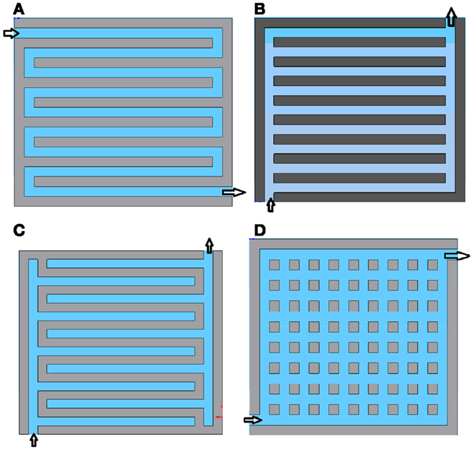
Figure 1. Typical flow channels designs leading to other versions of flow channel designs. (A) Serpentine; (B) Parallel; (C) Interdigitated; (D) Pin.
On the bases of these basic designs, we developed the graphite plates with seven different types of flow channels or flow fields. The comparison of the experimental results will allow us to have a profound understanding of the effect of the flow field designs to the fuel cell performance.
The graphite plates with various designs of flow fields for oxygen and hydrogen are shown in Figure 2. Of these designs, Figures 2A–C are the conventional designs, namely, single channel serpentine and multiple channel parallel, respectively. The difference of the multiple parallel channels in Figures 2B,C is the flow distribution. The flow fields in Figures 2D,E are evolved from designs of Figures 2B,C, respectively, having interrupted channel walls to form pillars. The flow channel design in Figure 2F is the so called interdigitated flow field, in which the supplied gases must diffuse laterally underneath the channel walls to flow to the channels for flowing out. A spiral flow channel design is shown in Figure 2G, which is essentially a single channel design.
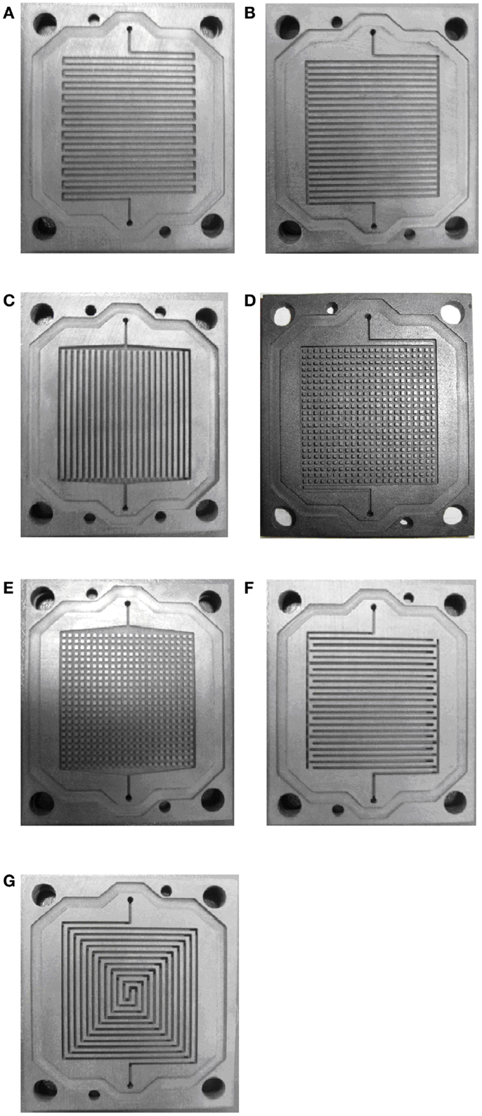
Figure 2. Photographs of graphite plates with gas flow channels for PEM fuel cells in the experimental tests. (A) Serpentine, (B) Parallel V1, (C) Parallel V2, (D) Pin V1, (E) Pin V2, (F) Interdigitated, and (G) Spiral.
The dimensions of machined graphite plates are shown in Figure 3. The total thickness of graphite plate is 5 mm. The channel depth is 1.0 and 2.0 mm for hydrogen and air flow channels, respectively. According to the authors’ earlier research work (Liu et al., 2013), the channel width and wall width have an effect on the cell performance. Therefore, the recommended channel and wall width ratios (preferably a smaller wall/channel ratio) were chosen for better efficiency. In this comparison study, all types of flow fields have a channel width of 1 mm and wall width of 1 mm for both anode side and cathode-side plates.
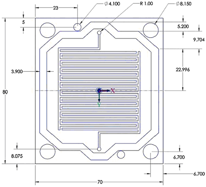
Figure 3. Dimensions of graphite plates with flow channels from the interdigitated flow field design.
With the flow field designs, engineering drawings of graphite plates were made in CAD software. The CAD drawings were imported to software Mastercam, which interpreted the drawing to G-codes for CNC machining process. All the graphite plates were fabricated using CNC machine to ensure high accuracy.
Cell Fabrication and Experimental Work
The experimental tests have been conducted in Energy and Fuel Cell Lab at the University of Arizona. The same type of membrane electrode assemblies (MEAs) from one manufacturer was used for all the tests, which include a membrane of Nafion 115 with platinum loadings of 0.4 mg/cm2. The MEA and gas diffusion layers were pre-laminated at factory with an effective area of 23.5 cm2. The gas diffusion layers are made of carbon fiber cloth.
Fuel Cell Assembling
The anode and cathode graphite plates, with flow channels fabricated, are assembled together with MEA. Two plastic end-plates are used to sandwich the fuel cell to maintain good electrical contact between all components. Since the electrical contact resistant between the graphite plates and the gas diffusion layers depends on pressure applied on the contacting surfaces (Yoon et al., 2004), all the assembly of the fuel cells should have the same compression to ensure that study and comparison of the fuel cell performance for other factors is based on the same contact resistance. A torque meter was used to indicate the same torque on the bolts when assembling a fuel cell.
Experimental Setup
The front panel of the experimental setup is shown in Figure 4. Key components in the setup are marked in the figure, which include: a hydrogen tank and pressure control valve, mass flow controllers for hydrogen, flow meter for air, air supply tubes with pressure regulation, humidity and temperature measurement equipment, humidifier to air and hydrogen, a single fuel cell, a load/resistance box, and a voltmeter.
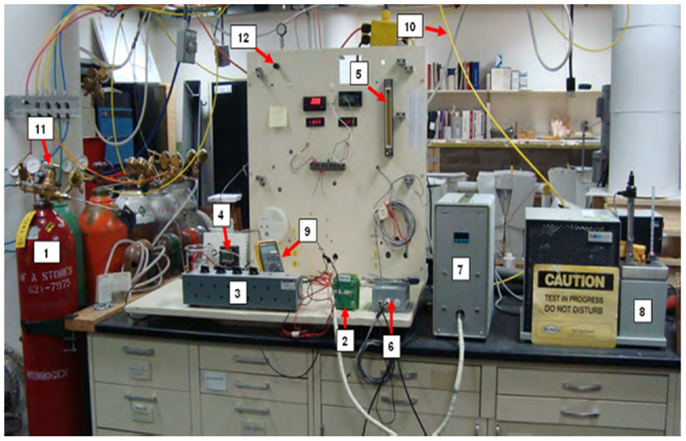
Figure 4. Experimental setup.
During the experiment, compressed air from the lab building was filtered, measured, and humidified before supplied to fuel cell. The airflow humidification is controlled by adjusting the dew point temperature (in a range of 30–80°C) of the humidifier. The supplied hydrogen was also humidified in a beaker with purified DI water before delivered to fuel cell anode flow channels. The hydrogen humidifier can also be maintained to have a constant temperature. Flow controllers (SERIRRA Smart Trak-2) was used to set and display flow rate of hydrogen. The flow rate of airflow is measured by a flow meter.
The fuel cell was connected with a load box, which provided an electrical load with a resistance in the range of 0.1–1000 Ω. The voltages from the cell were measured by a FLUKE voltmeter, and the current flow is then calculated from the measured voltage and the resistance of the load.
Result and Discussion
According to the authors’ former observation for the flow arrangements (concurrent or countercurrent flow) (Liu and Li, 2013a) in fuel cells, countercurrent flow of hydrogen versus air/oxygen showed better performance. Therefore, all PEM fuel cells tested in this work were conducted with countercurrent flow arrangement for hydrogen and air. The supplies of hydrogen and oxygen were more than that needed for the tested current densities.
Effect of Flow Field Designs
The performance of fuel cells due to the different designs of the flow channels is to be compared. In the tests, the hydrogen and air flow rates were set at constant of 189 and 1274 sccm, respectively, and the humidifiers of hydrogen and airflow have a dew point of 30°C. Figure 5 gives a comparison of the performance of single fuel cells having serpentine, parallel V1, pin V1, interdigitated, and spiral designs of flow fields. Figure 6 shows a comparison of the performance of fuel cells having serpentine, parallel V2, pin V2, interdigitated, and spiral designs of flow fields.
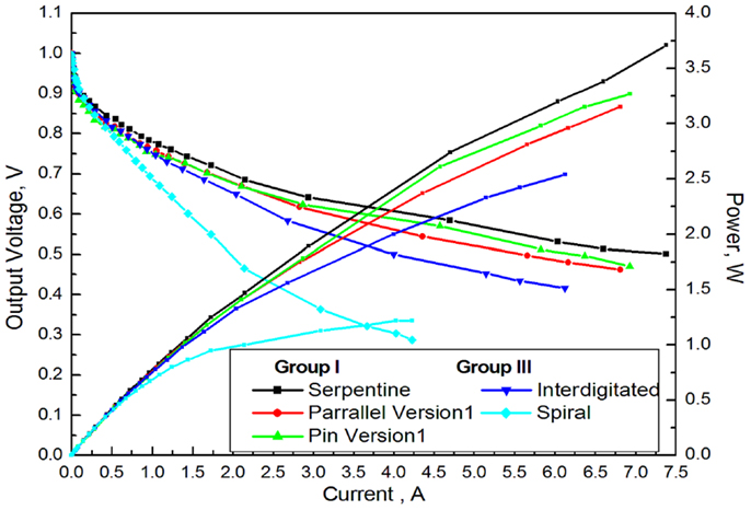
Figure 5. Comparison of cell output performance between group I and group III flow field designs.
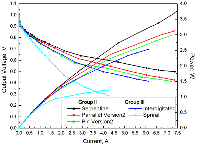
Figure 6. Comparison of cell output performance between group II and group III flow field designs.
It is observed from the above figures that flow field configurations play a significant role on the fuel cell’s voltage and power output. The fuel cell with the serpentine flow channel design offers the highest power output, while the spiral flow channel design gives the lowest power output. The interdigitated flow field design showed the second lowest output power compared to other types of flow field designs. The output power from the fuel cell with serpentine flow field is around 3.72 W, which is two times higher than the worst case due to spiral flow field design. The output performance of serpentine flow field over others in PEM fuel cells also has been reported by other researchers. Roshandel et al. has conducted CFD simulation and experimental test on PEM fuel cell with serpentine flow field, parallel flow, and bio pattern field. They found similar results that serpentine flow field outperforms parallel flow (Roshandel et al., 2012). Taccani and Zuliani (2011) has compared the performance of high temperature PEM fuel cell with multiple serpentine flow channels and parallel channels and found out that the former one generated higher power density than the later one under four sets of flow rates. Ferng et al. (2008) did experimental tests on PEM fuel cell and reported similar results. Lobato et al. (2010, 2011) had conduct experimental tests to compared four types of flow field designs – serpentine, parallel, pin, and interdigitated – and they found serpentine had the highest output power of all. Jang et al. (2008) numerically compared the performance of PEM fuel cell with four-channel serpentine, the so called Z-type flow field and parallel channel flow field, and they found that a cell with four-channel serpentine flow field showed the best performance. Wang et al. (2009) reported numerical computation of PEM fuel cells with serpentine, parallel, and interdigitated flow field, and the first one demonstrated the highest output power under a cross section area of 41 mm × 41 mm.
The serpentine flow field provides many advantages. The serpentine channel design has a flow field that could balance water removal (preventing water flooding) and an acceptable pressure drop, and at the same time, maintains a good humidity in the cathode channels, which prevents membrane dehydration (Li et al., 2007; Park and Li, 2007). Similar conclusion was observed by Jithesh et al. (2012) in their numerical study. The liquid water distribution inside the cell with serpentine flow field and parallel flow field from their work are shown in Figure 7. It is observed that serpentine flow field has water distributed and gradually increased from air inlet to outlet with a counter current supply of hydrogen. On the other hand, water was not uniformly spread out in the parallel channel flow field and there is a peak region with large amount of liquid water. The magnitude of the amount of water in this peak region for parallel flow field is much higher than that of serpentine flow field. Therefore, serpentine flow field improves the water distribution inside the cell and avoids excessive amount of water blocking the gas diffusion.
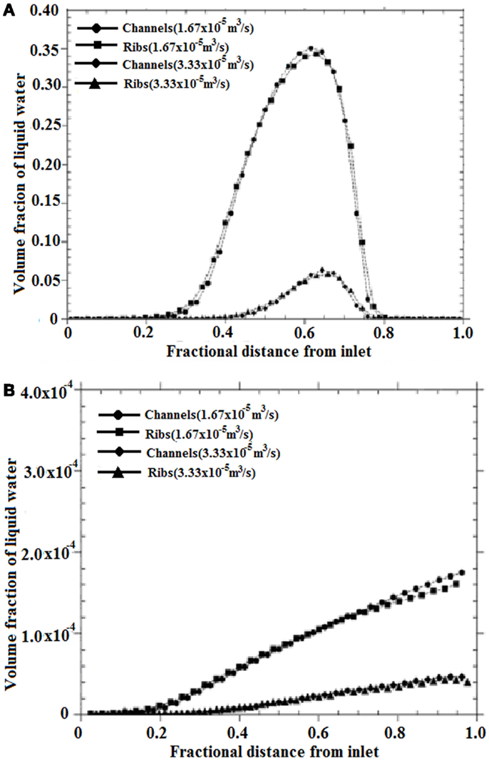
Figure 7. Water distribution inside the cell channel (Jithesh et al., 2012). (A) Parallel flow field and (B) serpentine flow field.
For the spiral flow channel design, it was examined and found that the ineffective water removal is responsible for the low power output. This was observed when the operated cell was opened and the remaining liquid water in the flow channels was visually examined. In the interdigitated flow channel design, an important characteristic is that all flow channels have a dead end. The flow must force the reactants in the channel to flow in-plane of GDL through its pores. This could bring in inevitable large pressure drop and increases the possibility of flooding on the cathode electrode.
Because the flow channel designs of pin versions 1 and 2 are evolved from the parallel channel designs of versions 1 and 2, the fuel cells using these flow field designs are specifically compared in Figure 8. The parallel version 1 and its evolved pin version 1 offer better performance of the fuel cell than that of their corresponding counterpart of parallel version 2 and its evolved pin version 2. The fuel cell with pin version 1 flow field has output power of 3.27 W, which is 10% higher than that of fuel cells using pin version 2. A better flow distribution in the flow fields of parallel version 1 and pin version 1 might be responsible to this output performance. It is also clear that at these tested low current densities, higher power densities were observed for the two fuel cells with pin version flow fields compared to their corresponding counterparts of parallel channel designs. This might be because that the pin type of flow field designs offer larger reactive area as well as enhanced mass transfer. After all, because of its output performance over all other tested flow field designs, serpentine flow field is recommended.
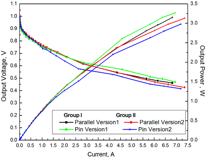
Figure 8. Comparison of the voltage and power output for fuel cells with two types of parallel flow channels and their evolved pin versions of flow fields.
Test of Fuel Cell Stack in Various Serpentine Flow Field Designs
The serpentine flow channel design was selected for the fuel cells in a stack as the single cell test showed excellent performance with this flow channel design. In case, if there is a large active area (or membrane area) in a fuel cell, multiple serpentine flow channels might be used, which makes the pressure loss relatively lower than that only has one long serpentine channel. Figure 8 shows three different designs of multiple serpentine flow channels (Figures 9B,D) compared to a single serpentine flow channel design for the tested fuel cell stacks. In these double serpentine and four serpentine channel designs, a special channel bifurcation structure was adopted to split a flow uniformly to two channels. Figure 9D shows a novel symmetric serpentine flow channel design proposed in this work. All the flow channels for the various serpentine flow fields have a width of 1 mm and wall width of 0.8 mm. The depth of the channels for hydrogen flow is 1 mm and for airflow is 2 mm. The hydrogen and airflow are arranged in countercurrent flow.
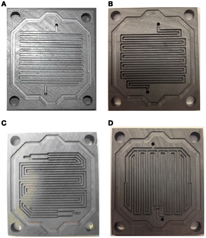
Figure 9. Four types of serpentine flow channels: (A) a single serpentine channel; (B) double serpentine flow channels; (C) four serpentine flow channels; and (D) a symmetric arrangement of four serpentine flow channels.
Each fuel cell stack includes four identical cells, including three identical bipolar plates and two mono-polar plates (one for airflow and one for hydrogen flow) assembled together with four identical MEAs. In order to provide the same amount of flow supply to all the four cells in a stack, an external uniform flow distributor was used. Details of uniform flow distributor are available from the authors’ earlier research work (Liu et al., 2012; Liu and Li, 2013a,b).
Every test of the fuel cell stack has a constant air flow rate of 3400 cm3 for the entire four cell stack. There are two tested hydrogen flow rates including 200 and 500 sccm for the cell stack. Both the hydrogen and airflow were humidified at 30°C. A countercurrent flow arrangement was adopted for hydrogen and airflow in each fuel cell in the stack. During the experiments, the remaining unused hydrogen and air from the fuel cell stack were simply discharged to the exhaust.
At a hydrogen flow rate of 200 sccm, the voltage and power of the fuel cell stacks with different serpentine flow channel arrangement (as shown in Figure 9) are demonstrated in Figure 10A. Because of the limited supply of hydrogen, the output power of the stacks is also not high. The cell stack with the symmetric arrangement of four serpentine flow channels has the highest power output of 9 W, which is followed by the stack that has single long serpentine channels in every cell. The cell stack with the four parallel serpentine flow channel design (Figure 9C) has the lowest power output of 7.2 W. The maximum and minimum power output among the four types of cell stacks has a significant difference of 20%.
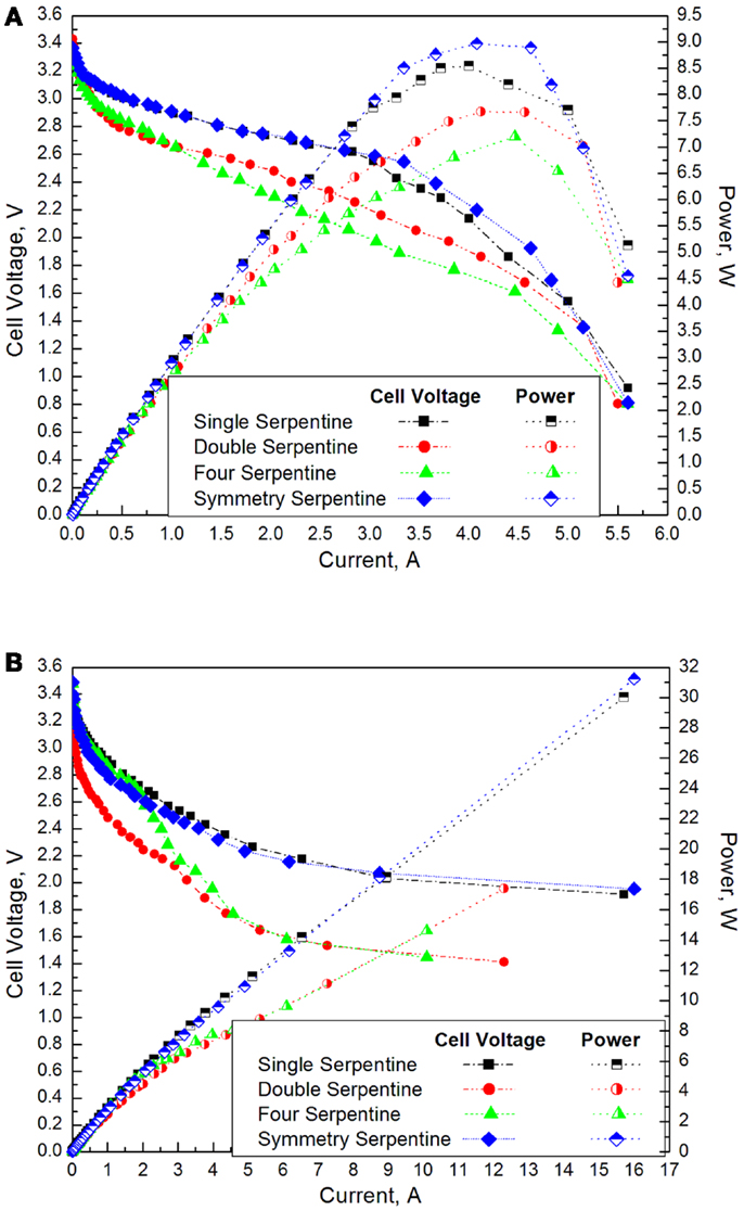
Figure 10. Fuel cell stack voltage and power. (A) Hydrogen flow rate of 200 sccm and (B) hydrogen flow rate of 500 sccm.
At a hydrogen flow rate of 500 sccm, significant increase of the output power is obtained. As seen in Figure 10B, the cell stack with symmetric arrangement of four serpentine channels has the highest power output followed by the stack that has single long serpentine flow channels in each cell. The other two cell stacks having parallel double and four serpentine flow channels (Figures 9B,C) have significantly low power output.
Because of the restriction of the minimum load resistance in the test, the experiment could not measure a power of more than 32 W. It is observed from the figure that cells with single serpentine flow channel and symmetry double serpentine flow channel presented better performance than double serpentine and four serpentine cases. A similar conclusion was reported in the work of Wang et al. (2008a). They numerically compared the performance of cells with single serpentine, double serpentine, and triple serpentine flow channels. They found that the output power of the cell with single serpentine is higher than the other two and the cell with triple serpentine showed the worst performance (Wang et al., 2008a). The maximum output power of the stack with symmetry four serpentine flow channel reached 31 W, which is 52 and 44% higher than the output power of the stacks with four parallel serpentine channel design and double serpentine channel design, respectively. The output power of the stack with novel symmetry double serpentine flow channel design is slightly better than the stack with single serpentine flow channel design. The novel design of the symmetric two serpentine flow channel is recommended for its excellent performance. Figure 11 shows the water distribution on the cathode graphite plate with counter flow supply of hydrogen and air. It is found that water uniformly distributed on the entire plate of the cell with symmetric double serpentine shown in Figure 11A. For the cell with four serpentine flow channel shown in Figure 11B, water only distributes on half of the plate close to the hydrogen inlet. This is an indication that the cell with symmetry double serpentine flow field has a better membrane hydration and utilization and produced higher power and voltage. On the other hand, the cell with four serpentine flow channel dose not effectively utilize the MEA area and the highly locally accumulated water could block the diffusion path for air, which will cause the cell performance drop at higher operation current.
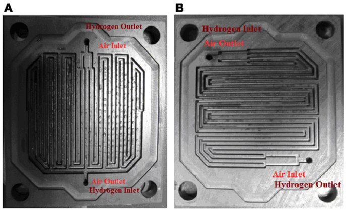
Figure 11. Photographs of water distribution in graphite cathode-side plate. (A) Symmetric double serpentine and (B) four serpentine.
Because of its four serpentine channels, it can be particularly suitable for large sized fuel cells as the pressure loss could be the concern in this case. The research team plans to conduct tests for a novel design concept in fuel cells with a membrane size of 20 cm × 20 cm in the near future.
To provide more information from the experimental work, the temperature of graphite end-plate of the fuel cell stack with single serpentine flow field was monitored by a digital thermometer (GTH 175/Pt) during a test as shown in Figure 12. It is observed that the temperature increases with operational current and the temperature variation is around 10°C. The thermal image of the fuel cell stack demonstrated the temperature distribution of all graphite plates as seen in Figure 13A. Figure 13B presents the temperature distribution along the green line marked in Figure 13A. It is found that end-plates have lower temperature than those bipolar plates in the center. The temperature distribution shows a good symmetry due to our novel stack architecture from uniform flow distribution design (Liu et al., 2010, 2012; Liu and Li, 2013b).
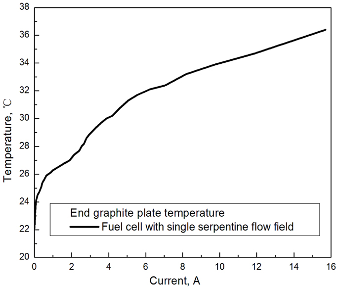
Figure 12. End-plate temperature distribution (under hydrogen flow supply of 500 sccm).
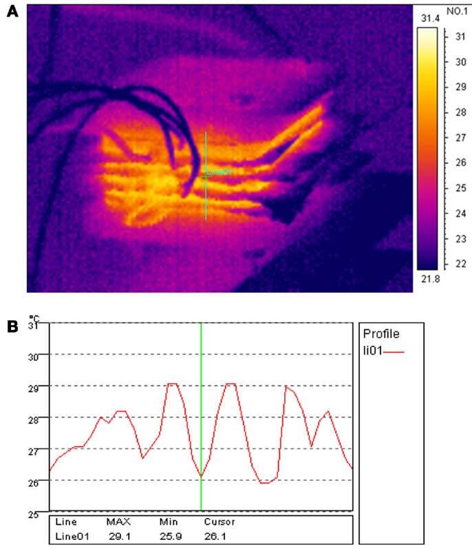
Figure 13. Fuel cell stack temperature distribution at operation current of 3 A. (A) Thermal image of fuel cell stack and (B) five graphite plate temperature distribution.
Conclusion
This work experimentally studied the effects of flow field designs on single PEM fuel cell performance firstly. Serpentine flow fields showed best performance among all designs studied in the work, while the spiral flow field design showed the worst performance. Observation showed that the water distribution inside the serpentine flow field relatively uniformly spread out. The amount of water in the entire channel and rib region is sufficient but not excessive to block the diffusion path.
The serpentine flow channel design was then chosen for further comparison of flow field design considering single serpentine and multiple serpentine channels for the flow field. Experimental tests of fuel cell stacks with different arrangement of serpentine flow channels were also conducted. It was found that the fuel cell stacks with single serpentine channel design and the currently proposed symmetric four serpentine channel arrangement both worked better. We observed that the cathode plate water distribution of cell with symmetric double serpentine effectively utilized the MEA area without excessive water blocking the diffusion path. Therefore, the novel symmetry serpentine multiple flow channel arrangement is particularly recommended for large sized fuel cells.
The temperature of graphite end-plate was monitored during the entire test. The bipolar plates in the center show higher temperature than the two end-plates.
Conflict of Interest Statement
The authors declare that the research was conducted in the absence of any commercial or financial relationships that could be construed as a potential conflict of interest.
References
Aiyejina, A., and Sastry, M. K. S. (2012). PEMFC flow channel geometry optimization: a review. J. Fuel Cell Sci. Technol. 9, 011011. doi: 10.1115/1.4005393
Akhtar, N., Qureshi, A., Scholta, J., Hartnig, C., Messerschmidt, M., and Lehnert, W. (2009). Investigation of water droplet kinetics and optimization of channel geometry for PEM fuel cell cathodes. Int. J. Hydrogen Energy 34, 3104–3111. doi:10.1016/j.ijhydene.2009.01.022
Cao, T., Li, H. L., Chen, L., He, Y. L., and Tao, W. Q. (2013). Numerical investigation of the coupled water and thermal management in PEM fuel cell. Applied Energy 112, 1115–1125. doi:10.1016/j.apenergy.2013.02.031
Chen, Y. S., and Peng, H. (2011). Predicting current density distribution of proton exchange membrane fuel cells with different flow field designs. J. Power Sourc. 196, 1992–2004. doi:10.1016/j.jpowsour.2010.09.094
Dokkar, B., Eddine Settou, N., Imine, O., Saifi, N., Negrou, B., and Nemouchi, Z. (2011). Simulation of species transport and water management in PEM fuel cells. Int. J. Hydrogen Energy 36, 4220–4227. doi:10.1016/j.ijhydene.2010.09.060
Ferng, Y. M., Su, A., and Lu, S. M. (2008). Experiment and simulation investigations for effects of flow channel patterns on the PEMFC performance. Int. J. Energ. Res 32, 12–32. doi:10.1002/er.1320
Jang, J., Yan, W., Li, H., and Tsai, W. (2008). Three-dimensional numerical study on cell performance and transport phenomena of PEM fuel cells with conventional flow fields. Int. J. Hydrogen Energy 33, 156–164. doi:10.1016/j.ijhydene.2007.09.005
Jiao, K., Zhou, B., and Quan, P. (2006). Liquid water transport in parallel serpentine channels with manifolds on cathode side of a PEM fuel cell stack. J. Power Sourc. 154, 124–137. doi:10.1016/j.jpowsour.2005.04.003
Jithesh, P. K., Bansode, A. S., Sundararajan, T., and Sarit, K. D. (2012). The effect of flow distributors on the liquid water distribution and performance of a PEM fuel cell. Int. J. Hydrogen Energy 37, 17158–17171. doi:10.1016/j.ijhydene.2012.08.058
Khakpour, M., and Vafai, K. (2008). Analysis of transport phenomena within PEM fuel cells – an analytical solution. Int. J. Heat Mass Transf. 51, 3712–3723. doi:10.1016/j.ijheatmasstransfer.2007.12.013
Li, X., Sabir, I., and Park, J. (2007). A flow channel design procedure for PEM fuel cells with effective water removal. J. Power Sourc. 163, 933–942. doi:10.1016/j.jpowsour.2006.10.015
Liu, H., and Li, P. (2013a). Maintaining equal operating conditions for all cells in a fuel cell stack using an external flow distributor. Int. J. Hydrogen Energy 38, 3757–3766. doi:10.1016/j.ijhydene.2013.01.022
Liu, H., and Li, P. (2013b). Even distribution/dividing of single-phase fluids by symmetric bifurcation of flow channels. Int. J. Heat Fluid Flow 40, 165–179. doi:10.1016/j.ijheatfluidflow.2013.01.011
Liu, H., Li, P., and Van Lew, J. (2010). CFD study on flow distribution uniformity in fuel distributors having multiple structural bifurcations of flow channels. Int. J. Hydrogen Energy 35, 9186–9198. doi:10.1016/j.ijhydene.2010.06.043
Liu, H., Li, P., Van Lew, J., and Juarez-Robles, D. (2012). Experimental study of the flow distribution uniformity in flow distributors having novel flow channel bifurcation structures. Exp Therm Fluid Sci 37, 142–153. doi:10.1016/j.expthermflusci.2011.10.015
Liu, H., Li, P., and Wang, K. (2013). Optimization of PEM fuel cell flow channel dimensions-mathematic modeling analysis and experimental verification. Int. J. Hydrogen Energy 38, 9835–9846. doi:10.1016/j.ijhydene.2013.05.159
Liu, X., Guo, H., and Ma, C. (2006). Water flooding and two-phase flow in cathode channels of proton exchange membrane fuel cells. J. Power Sourc. 156, 267–280. doi:10.1016/j.jpowsour.2005.06.027
Liu, X., Guo, H., Ye, F., and Ma, C. (2008). Flow dynamic characteristics in flow field of proton exchange membrane fuel cells. Int. J. Hydrogen Energy 33, 1040–1051. doi:10.1016/j.ijhydene.2007.11.018
Lobato, J., Cañizares, P., Rodrigo, M. A., Pinar, F. J., Mena, E., and Úbeda, D. (2010). Three-dimensional model of a 50 cm2 high temperature PEM fuel cell: study of the flow channel geometry influence. Int. J. Hydrogen Energy 35, 5510–5520. doi:10.1016/j.ijhydene.2010.02.089
Lobato, J., Cañizares, P., Rodrigo, M. A., Pinar, F. J., and Úbeda, D. (2011). Study of flow channel geometry using current distribution measurement in a high temperature polymer electrolyte membrane fuel cell. J. Power Sourc. 196, 4209–4217. doi:10.1016/j.jpowsour.2010.10.017
Park, J., and Li, X. (2007). An experimental and numerical investigation on the cross flow through gas diffusion layer in a PEM fuel cell with a serpentine flow channel. J. Power Sourc. 163, 853–863. doi:10.1016/j.jpowsour.2006.09.083
Peng, L., Mai, J., Hu, P., Lai, X., and Lin, Z. (2011). Optimum design of the slotted-interdigitated channels flow field for proton exchange membrane fuel cells with consideration of the gas diffusion layer intrusion. Renew. Energ. 36, 1413–1420. doi:10.1016/j.renene.2010.11.031
Roshandel, R., Arbabi, F., and Karimi Moghaddam, G. (2012). Simulation of an innovative flow-field design based on a bio inspired pattern for PEM fuel cells. Renew. Energ. 41, 86–95. doi:10.1016/j.renene.2011.10.008
Siegel, C. (2008). Review of computational heat and mass transfer modeling in polymer-electrolyte-membrane (PEM) fuel cells. Energy 33, 1331–1352. doi:10.1016/j.energy.2008.04.015
Su, A., Weng, F., Hsu, C., and Chen, Y. (2006). Studies on flooding in PEM fuel cell cathode channels. Int. J. Hydrogen Energy 31, 1031–1039. doi:10.1016/j.ijhydene.2005.12.019
Sun, H., Liu, H., and Guo, L. J. (2005). PEM fuel cell performance and its two-phase mass transport. J. Power Sourc. 143, 125–135. doi:10.1016/j.jpowsour.2004.11.034
Suresh, P. V., and Jayanti, S. (2010). Effect of air flow on liquid water transport through a hydrophobic gas diffusion layer of a polymer electrolyte membrane fuel cell. Int. J. Hydrogen Energy 35, 6872–6886. doi:10.1016/j.ijhydene.2010.04.052
Taccani, R., and Zuliani, N. (2011). Effect of flow field design on performances of high temperature PEM fuel cells: experimental analysis. Int. J. Hydrogen Energy 36, 10282–10287. doi:10.1016/j.ijhydene.2010.10.026
Wang, X. D., Duan, Y. Y., and Yan, W. M. (2007). Novel serpentine-baffle flow field design for proton exchange membrane fuel cells. J Power Sources 173, 210–221. doi:10.1016/j.jpowsour.2007.08.037
Wang, X. D., Duan, Y. Y., Yan, W. M., and Peng, X. F. (2008a). Local transport phenomena and cell performance of PEM fuel cells with various serpentine flow field designs. J. Power Sourc. 175, 397–407. doi:10.1016/j.jpowsour.2007.09.009
Wang, X. D., Duan, Y. Y., Yan, W. M., and Peng, X. F. (2008b). Effects of flow channel geometry on cell performance for PEM fuel cells with parallel and interdigitated flow fields. Electrochim. Acta 53, 5334–5343. doi:10.1016/j.electacta.2008.02.095
Wang, X., Zhang, X., Yan, W., Lee, D., and Su, A. (2009). Determination of the optimal active area for proton exchange membrane fuel cells with parallel, interdigitated or serpentine designs. Int. J. Hydrogen Energy 34, 3823–3832. doi:10.1016/j.ijhydene.2008.12.049
Watkins, D. S., Dircks, K. W., and Epp, D. G. (1992). Fuel Cell Fluid Flow Field Plate, U.S. Patent 5, 108,849.
Keywords: PEM fuel cell, flow field, experiment, comparison, novel design
Citation: Liu H, Li P, Juarez-Robles D, Wang K and Hernandez-Guerrero A (2014) Experimental study and comparison of various designs of gas flow fields to PEM fuel cells and cell stack performance. Front. Energy Res. 2:2. doi: 10.3389/fenrg.2014.00002
Received: 02 December 2013; Accepted: 06 January 2014;
Published online: 24 January 2014.
Edited by:
Shanwen Tao, University of Strathclyde, UKReviewed by:
Zhenxing Liang, South China University of Technology, ChinaArunachala Mada Kannan, Arizona State University, USA
Copyright: © 2014 Liu, Li, Juarez-Robles, Wang and Hernandez-Guerrero. This is an open-access article distributed under the terms of the Creative Commons Attribution License (CC BY). The use, distribution or reproduction in other forums is permitted, provided the original author(s) or licensor are credited and that the original publication in this journal is cited, in accordance with accepted academic practice. No use, distribution or reproduction is permitted which does not comply with these terms.
*Correspondence: Peiwen Li, Department of Aerospace and Mechanical Engineering, The University of Arizona, 1130 North Mountain Avenue, Tucson, AZ 85721, USA e-mail: peiwen@email.arizona.edu