Low-Concentration Solar-Power Systems Based on Organic Rankine Cycles for Distributed-Scale Applications: Overview and Further Developments
 Christos N. Markides
- Clean Energy Processes (CEP) Laboratory, Department of Chemical Engineering, Imperial College London, London, UK
This paper is concerned with the emergence and development of low-to-medium-grade thermal-energy-conversion systems for distributed power generation based on thermodynamic vapor-phase heat-engine cycles undergone by organic working fluids, namely organic Rankine cycles (ORCs). ORC power systems are, to some extent, a relatively established and mature technology that is well-suited to converting low/medium-grade heat (at temperatures up to ~300–400°C) to useful work, at an output power scale from a few kilowatts to 10s of megawatts. Thermal efficiencies in excess of 25% are achievable at higher temperatures and larger scales, and efforts are currently in progress to improve the overall economic viability and thus uptake of ORC power systems, by focusing on advanced architectures, working-fluid selection, heat exchangers and expansion machines. Solar-power systems based on ORC technology have a significant potential to be used for distributed power generation, by converting thermal energy from simple and low-cost non-concentrated or low-concentration collectors to mechanical, hydraulic, or electrical energy. Current fields of use include mainly geothermal and biomass/biogas, as well as the recovery and conversion of waste heat, leading to improved energy efficiency, primary energy (i.e., fuel) use and emission minimization, yet the technology is highly transferable to solar-power generation as an affordable alternative to small-to-medium-scale photovoltaic systems. Solar-ORC systems offer naturally the advantages of providing a simultaneous thermal-energy output for hot water provision and/or space heating, and the particularly interesting possibility of relatively straightforward onsite (thermal) energy storage. Key performance characteristics are presented, and important heat transfer effects that act to limit performance are identified as noteworthy directions of future research for the further development of this technology.
Introduction and Motivation
The recently heightened interest in issues relating to energy and the environment has given rise to an intensified debate in the public domain, the scientific community, industry, government and policy circles, and even the financial and investment sectors, concerning the role that a wide variety of energy (fuel-to-power and heat-to-power) technologies can play within competing visions of both global and national energy futures. Rapid developments have been observed in the areas of energy generation, management (transportation, conversion, storage and supply) and consumption in all their facets, spanning a range of scales and diverse applications. An important aspect of the energy challenge concerns the harnessing of renewable and sustainable energy sources, such as the solar resource, for the provision of power, heating, and also, depending on the need, cooling (Markides, 2013). The IEA projects that solar energy has the potential to cover one-third of the world’s energy consumption by 2060 under favorable conditions. This represents a significant displacement in the utilization of fossil fuels, and thus both in the consumption of this finite resource and in the consequent release of harmful emissions to the atmosphere.
Although fossil fuels will remain the most important (and dominant) primary energy resource over the next decades, renewable energy technologies have received particular attention in both developed and developing countries, yet for different reasons. In the case of the former, the attention has been strongly supported by public opinion, driven by a desire for energy diversification and decarbonization in an effort to move away from an existing reliance on fossil fuels and toward a more secure, clean, and sustainable energy portfolio. In the latter, including in China, India, and the rest of the BRICKS, this has arisen in response to a need to drive the strong economic growth that is being experienced and a desire to raise living standards, which are known to correlate with higher energy use (MacKay, 2009; Markides, 2013), while addressing health (e.g., clean environment) concerns that have emerged from rapid industrialization. In both cases, these trends have established renewable technologies as an indispensable contributor to energy generation, with exponential growth experienced in the sector in recent decades.
Solar-based renewable energy systems can be deployed to deliver electricity and also to provide hot water, generate space heating and even cooling at different application scales, depending on the specific requirements and the technologies employed. It is generally accepted that photovoltaic (PV) panels and solar-thermal (ST) collector systems are highly suitable options for onsite renewable energy generation. The former can provide an electrical-energy output to cover end-users’ electricity needs, while the latter can provide a thermal-energy output for water or space heating at much higher efficiency [50–80% (Freeman et al., 2015a)]. A UK-based analysis by McKinsey in 2007 identified solar hot water as the leading solution in terms of greenhouse gas (GHG) abatement potential (Confederation of British Industry, 2007), even in this northern climate with its restricted solar resource compared to other regions.
The PV market has been experiencing a well-documented exponential growth for over two decades, driven strongly by installations in Europe, and more recently Asia, assisted by a broad range of incentivization programs. Global installed capacity has been increasing on average by at least 40% year-on-year, and in some cases close to 50%, with a doubling time of 1.8–2.0 years over the last 20 years. At the same time, costs have been decreasing strongly, driven by increased production mainly in China, to the point where solar PV is now close to achieving “grid parity” (i.e., at a price competing with the purchase of conventional power from the electricity grid). The price of crystalline silicon (c-Si) solar cells has been falling by 10–15% per year with a 4.5–5.0-year halving time over the last 30 years. Currently, the largest PV power station in the world (the Topaz Solar Farm in the US) stretches over 25 km2 and has a ~0.5 GWp peak capacity; given actual load factors and performance, this corresponds to an output of up to ~1 TWh/year (~0.1 GW or 3.6 PJ/year).
When considering electricity generation from solar energy, and with exception of large/utility-scale (defined as >4–5 MW, Wolfe, 2015) ST power-generation plants, the focus is often placed exclusively on PV, typically flat-panel non-concentrated PV based on a range of semiconductor materials. Arguably, this practice is done to an extent that, for the most part, PV technologies are often mentioned synonymously with solar energy, thus largely displacing ST power from the discussion. Nevertheless, large-scale ST power plants based invariably on concentrated solar collectors (mainly parabolic trough concentrators with single-axis solar tracking, but also solar tower receivers with two-axis tracking heliostats), and referred to as concentrated solar-power (CSP) plants, are also a mature technology which is suitable for solar-power generation. The largest CSP plant in the world (Ivanpah Solar Power Facility, USA) covers 14 km2 and has a rating of ~0.4 GW (or 13 PJ/year).
The global overall operational (full-load) capacity of utility-scale PV power stations amounted to ~36 GWp (or, ~7 GW) at the end of 2014 (Wolfe, 2015) (at the same time, total cumulative capacity across all scales was closer to 180 GWp, or 30 GW), while that of utility-scale CSP electricity production reached ~4 GW at the end of 2013 and was projected to approach ~5 GW at the end of the same period as above (i.e., 2014) (Hashem, 2015). The levelized electricity cost (LEC) of CSP is similar to that of PV (both fall in the range ~$100–200/MWh depending on the scale of application), although CSP has an edge in terms of efficiency (Lazard, 2013; Markides, 2013). Cradle-to-grave GHG emissions from the solar options are also comparable. A meta-analysis reported in Markides (2013) gave for PV: 18–67 g for thin-film CdTe and 32–104 g for Si and for CSP: 14–90 g for trough, 21–60 g for receiver, and 22–58 gCO2/kWh for dish collectors. Importantly, up to 15 h of thermal storage can be provided in the case for demand matching and load factor improvement at a fraction of the cost of equivalent-scale electricity storage.
Yet beyond conventional solar-power from PV and CSP, hybrid PV-ST (PVT) systems and also solar combined heat and power (S-CHP) systems based on non-concentrated or low-concentration ST collectors in conjunction with thermodynamic power cycles are alternative solar-energy options in smaller/distributed-scale applications, which offer the distinct advantage of providing from a single system both a thermal-energy (e.g., for water heating) and an electrical-energy output. These systems are unlikely to be considered for large-scale use, since the thermal output, although equally (if not more, arguably, in certain northern regions) important, is less fungible compared to electricity. Still, distributed ST power systems based on these technologies can and should play a role in a future with increased penetration of renewable technologies into the energy landscape.
Solar Hybrid and Combined Heat and Power Systems
In hybrid PVT systems, the synergistic combination of ST and PV technology allows for the electrical and thermal outputs to be obtained simultaneously, while reducing the losses in the electrical efficiency of the PV module caused by the increase in the operating temperature of the cell due to solar heating. The loss reduction is achieved in practice by using a cooling flow of either air or water through or over the unit. If designed correctly, this allows improved efficiencies compared to stand-alone PV modules (Herrando et al., 2014), while also making available a hot stream of air or water as a thermal output from the system that can be used for hot water provision, space heating, or cooling.
Current applications of hybrid PVT systems typically prioritize the electrical output, which requires the panels and thus the cooling fluid (air or water) to be kept at a low temperature. This allows the PV cells to achieve high electrical efficiencies but also decreases the usefulness of the thermal output. On the other hand, if a PVT system is designed to provide higher cooling-fluid delivery temperatures, then the PV cell efficiency will deteriorate to some extent relative to the optimal electrical power-output setting. Hence a trade-off between the two outputs is sought that depends on the end-user needs.
It is necessary to consider that PVT panels are associated with significantly higher (approximately ×2) capital costs per unit area compared to PV-only equivalents (Herrando et al., 2014). This introduces competition from ST-based alternative solar-energy options that are also capable of providing combined thermal and electrical-energy outputs, such as S-CHP systems (Freeman et al., 2015b). S-CHP systems employ ST collectors to convert solar radiation into a hot fluid-stream (i.e., an enthalpy flow) and a power-generation component to convert this (partially) to a mechanical or hydraulic output. The focus here is on simple and affordable non-concentrated and low-concentration collectors, and power generation based on thermodynamic power cycles (i.e., heat engines). From this mechanical or hydraulic output, electrical power can be generated with the use of generators. S-CHP systems can, therefore, be used to deliver heating and a mechanical, hydraulic or electrical power output depending on the requirements of the application. In addition, as is the case with PVT technology, the thermal output can be used for hot-water provision, space heating, or cooling. Since these systems are based fundamentally on the use of thermal energy, including for the generation of the electrical output, they benefit naturally from thermal-energy storage (TES) as a part of their operation.
One aspect of S-CHP technology that is of importance concerns suitable ST collector designs for such systems. Given the coupling of the performance of the ST collector component(s) and that of the power-generating component(s), optimized S-CHP systems require collectors that are designed to operate efficiently at temperatures higher than those typically associated with solar hot-water provision. Although conventional collectors can be utilized in such systems, this is an area of particular interest.
Recent simulations relevant to Northern European climatic conditions (specifically, the UK) have shown that a simple domestic S-CHP system-design operating with a 15 m2 rooftop collector array (specifically, conventional non-tracking evacuated-tube collectors) can produce power in the region of 700–780 kWeh/year (continuous power of 80–90 We) and displace 310–350 kgCO2(e) in emissions at a capital cost of $6,800–8,500, of which $4,200–6,000 is attributed to electrical power generation and the rest to solar hot-water heating. This corresponds to an installed total cost per unit power generation of $85–95/We, $53–68/We of which is associated with electricity generation alone. This system also demonstrated a potential for producing up to 86% of the household’s hot-water requirement, corresponding to an additional 470 kgCO2(e) in emission reductions (Freeman et al., 2015b). With an advanced system architecture incorporating a two-stage solar collector/evaporator configuration and a more suitable working fluid, a maximum net annual electrical-work output of 1,070 kWeh/year (122 We) and a solar-to-electrical efficiency of 6.3% have been reported (Freeman et al., 2015c). This would cover ~32% of the electricity demand of a typical, average UK home, and represents an improvement of more than 50% over the previous effort by the same authors. By comparison, a similarly sized (15 m2) c-Si PV system costing around $11,600 can be expected to output 200 We in the same climate, at an installed cost of ~$59/We; a value in the middle of the $53–68/We range given above for the simple S-CSHP system. The purchase and installation cost of equivalent side-by-side PV and ST systems (covering the same area) would range from $14,700 to $15,500, giving a cost per unit generating capacity of ~$113/We. This figure can be directly compared to the $85–95/We range that was given above for the simple S-CHP system. For a PVT system, the purchase and installation cost is in the region $12,400–13,200, with a cost per unit capacity of ~$59/We based on an output of ~215 We. This value may appear lower than the total capital cost per unit delivered power by the simple S-CHP system ($85–95/We); however, the PVT alternative has a significantly reduced capacity for hot water provision, amounting to 35% of household consumption at best (as predicted in Herrando et al., 2014).
The present author stated in Markides (2013) that “In summary, dwindling resources and rising energy prices, together with a growing public acceptance and even demand for government regulation to address sustainable development, environmental and health concerns, fuel economy and energy security issues are acting, and will continue to act, as major and intensifying drivers for the widespread application of energy efficiency schemes and the utilization of alternative energy sources to fossil fuels.” In this present paper we are concerned with non-concentrated and low-concentration combined solar systems (i.e., S-CHP) for the supply of electricity, and if necessary also hot water and/or space heating or cooling. Furthermore, the interest is in distributed applications in the domestic (1–10 kWe) and commercial/industrial (10–100 s of kWe) sectors, i.e., individual households, whole residential and commercial buildings, and industrial plants. Therefore, the conversion technologies considered here cover a range of (electrical) power-output scales from 1 kWe to 1 MWe. As a rough guide, scales of the order of ~100 kWth (thermal) and ~10 kWe (electric) would correspond to approximate collection areas of the order of 1,000 m3 (or, ~30 m × 30 m). In addition, the focus is on heat-source temperatures below 400°C.
The following sections attempt to justify rationally the interest in suitable solar-energy technologies based on thermodynamic power cycles, focusing in particular on power-generation performance, costs, and other important characteristics. Aspects of scale and the use of distributed versus centralized energy systems will be discussed, and suitable technologies that can contribute in the short-to-medium term toward a high efficiency and sustainable energy future will be identified.
Technology Appraisal
Efficiency Considerations of Common Systems
Figure 1 is a performance map that shows the thermal efficiencies, ηth, of common power systems over a range of heat-source temperatures, Thot, from 100 to 1,400°C. Included in this figure is the relative performance of thermoelectric generators (TEGs), a competing technology for thermal-energy conversion directly to electricity based on the Seebeck effect. The maximum thermodynamic limit imposed by the Carnot efficiency, ηC = ηth = 1 − Tcold/Thot, is indicated by the blue line, and the Novikov and Curzon–Ahlborn efficiency results from endoreversible analyses, ηth = 1 − (Tcold/Thot)0.5, is indicated by the green line. A heat sink is selected with a fixed temperature Tcold = 25°C.
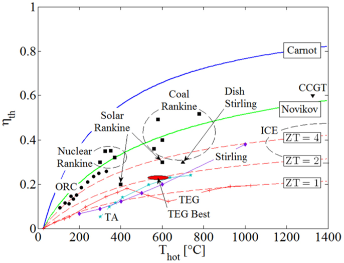
Figure 1. Thermal efficiency, ηth, of common thermodynamic heat engines and TEGs over a range of heat-source temperatures, Thot. The circles represent actual ORC and Kalina cycles’ applications; squares are for various Rankine cycles; triangles for solar dish Stirling and CCGT cycles; diamonds for conventional Stirling; and stars for TA engines. The solid red line represents the current performance of TEGs, with the three dashed red lines indicating TEG figure-of-merits ZT = 1, 2, and 4.
The circular points in Figure 1 represent systems based on organic Rankine cycle (ORC) and Kalina (ammonia–water) cycles in actual solar, geothermal and waste-heat plants up to Thot ≈ 350°C (Bianchi and Pascale, 2011). The square points represent, in order of increasing heat-source temperature:
• Thot ≈ 300–400°C: large-scale nuclear-powered steam-Rankine cycles;
• Thot ≈ 400–600°C: large-scale CSP Rankine cycles; and
• Thot ≈ 550–800°C: large-scale conventional coal-fired Rankine and advanced supercritical coal Rankine cycles.
In addition, the diamond points in the figure are taken from Nightingale (1986) and Bianchi and Pascale (2011), and represent the performance of Stirling-engine cycles, while the triangle at Thot ≈ 700°C represents a highly concentrated solar-dish Stirling cycle. The stars are from the high-performance (traveling-wave) thermoacoustic (TA) engine reported in Backhaus and Swift (2000). Internal combustion engines (ICEs) based on Diesel and Otto cycles are also shown on the far left of the figure, along with a combined-cycle gas turbine (CCGT), i.e., Joule/Brayton top cycle plus Rankine bottoming cycle, at Thot > 1,300°C.
The solid red line in Figure 1 indicates current performance of TEGs, and the three dashed red lines indicate theoretical efficiencies, ηth = ηC × [(1 + ZT)0.5 − 1]/[(1 + ZT)0.5 + Tcold/Thot], attained by TEGs given figure-of-merits: ZT = 1, 2, and 4. As above, a heat sink temperature of Tcold = 25°C is used. In this expression, the modifying ratio multiplied by the Carnot efficiency accounts for Joule losses (i.e., losses due to parasitic electrical power dissipation and conversion to heat) and other inherent irreversible processes in TEGs (Snyder and Toberer, 2008). In evaluating the performance of actual TEG systems, ZT(Thot) values for different materials were taken (Li et al., 2010; Szczech et al., 2011) and used in this expression at the corresponding heat-source temperature, Thot, at which they are mentioned in the stated references. The dashed lines where generated with this same expression, assuming that the value ZT is maintained constant over the range of investigated heat-source temperatures, Thot. It is noted that current “best” performance in terms of ZT (also indicated in Figure 1), is around 2.1 at 800 K/530°C (Hsu et al., 2004) and 2.2 at 900 K/630°C (Biswas et al., 2012) attained under laboratory conditions, while commercially available systems can be found with ZT values of unity (ZT ≈ 1). Vining (2009) also mentions a material with a ZT value of 3.5, but this does not yet lend itself to being produced in bulk quantities as would be required in practical applications.
The value of ZT = 4 is referred to in Vining (2009) as being “ambitious,” yet possibly feasible. The opinion of the present author is that a significant breakthrough will be required to attain a working, commercially available and economically competitive TEG system operating at an average value of ZT = 4, and even then it is unlikely to emerge in the range of power-output scales and temperatures that are of interest here, i.e., >1 kW and <400°C. Therefore, the inescapable conclusion from Figure 1, which is reached also by Vining (2009), is that although TEGs may yet become appropriate for small-scale applications which require power outputs <100 W, it is unlikely that they will play a role in the type and range of applications that are considered in the present work, i.e., >1 kW and <400°C.
It can also be seen from Figure 1, as would be expected from simple thermodynamic principles, that plants based on vapor-cycle heat engines (i.e., involving phase change) outperform gas-phase heat engines for heat-source temperatures <700–800°C. This is due to the significant penalty paid for the compression of the gas relative to the power produced during expansion.
Moreover, the figure suggests that ORCs are the preferred heat-conversion technology at temperatures <400°C. It is both interesting and important to consider the reasons for which ORCs have the potential to outperform equivalent power-generation systems such as conventional steam-Rankine cycles at these lower temperatures, especially in the power range of our focus applications, i.e., 1 kW to 1 MW. This is done in Section “Rankine Cycle Ideal Maximum Power,” but before we proceed to these considerations, a brief mention ought to be made of alternative technologies that have been attracting increased interest recently owing to their suitability for use with low-grade (i.e., temperature) heat sources, such as ST energy, in the same applications and, therefore, range of temperatures and scales.
Alternative Technologies
Thermofluidic oscillators are unsteady thermodynamic heat-engine devices in which persistent and reliable thermodynamic property (pressure, temperature, etc.) oscillations are generated and sustained by constant temperature differences imposed by static external heat sources and sinks. A defining characteristic of these unsteady heat engines is that the working fluid contained within the device undergoes a thermodynamic cycle by virtue of the oscillatory time-varying flow of the fluid through the various connections (i.e., pipes and tubes) and compartments of the device. Oscillatory working-fluid motion is thus a necessary condition for operation, in direct contrast to conventional systems in which the cycle is undergone as the working fluid flows steadily from one individual component to the next, with each component responsible for a specific and well-defined process of the cycle. Common examples of such systems are TA engines, and Fluidyne and Stirling engines. As shown in Figure 1, however, the efficiency of these devices is limited at lower temperatures, a characteristic which is in some applications can be offset by their simple designs, long lifetimes, and low costs.
Two-phase thermofluidic oscillators (TFOs) (Smith, 2006) share a common feature with these types of devices in that reciprocating, positive-displacement work is produced by sustained flow and pressure oscillations of the working fluid. TFOs are vapor-phase heat engines, in that a cyclic (periodic) two-phase thermal interaction with two heat exchangers (hot and cold) contained within the device is established. The hot heat exchanger (HHX) introduces a high-temperature region inside the device (hotter than the saturation temperature of the working fluid), while the cold heat exchanger (CHX) introduces a cold-temperature region. The alternating thermal interaction of the working fluid with the hot and cold regions results in periodic evaporation and condensation processes that induce the forcing necessary to sustain the thermodynamic cycle and to drive the positive-displacement work done by the fluid in a suitable load.
Therefore, it can be noted that the key, defining characteristic of TFOs compared to (single-phase) TA engines, Fluidyne and Stirling engine variants is their inherent reliance on phase change during operation. This choice carries a set of important advantages and also inevitable disadvantages. One key advantage arises from the high heat transfer coefficients that are associated with phase change, which can be an order of magnitude (or more) higher than those associated with single-phase forced convection. This allows significant heat transfer over relatively small temperature differences, which is important when dealing with low-grade heat sources, and also over smaller areas. In turn, it implies smaller, more compact, and simpler heat exchangers, which has a direct implication on the eventual capital costs of these systems; an important consideration especially for the conversion of solar and other renewable energy streams (e.g., geothermal), as well as waste heat (see Section “Cost Considerations”).
Example TFO devices are the “Non-Inertive-Feedback Thermofluidic Engine” (NIFTE) (Markides and Smith, 2011; Solanki et al., 2012, 2013a,b; Markides and Gupta, 2013; Markides et al., 2013, 2014; Palanisamy et al., 2015) that is being developed as a solar-powered fluid pump, and the even more recent “liquid Stirling engine” (also known as the “Up-THERM” engine) (Glushenkov et al., 2012) that is currently under development as a combined heat and power (CHP) prime-mover. In both cases, these technologies are suited also to the conversion of ST energy, and a key strength is their simple construction with a reduced number of moving parts and dynamic seals, thus leading to low capital and maintenance costs and long lifetimes, as mentioned earlier. However, although the thermodynamic performance of these TFOs has improved significantly in recent years, it is expected to remain considerably lower than that of equivalent ORC power systems, at least for heat-source temperatures upwards of 80°C. Specifically for the NIFTE, thermal, and exergy efficiency values at low temperatures (<100–200°C) are expected to remain within the range originally predicted in Markides (2013) for this technology, i.e., 1–5% and 5–20%, respectively, depending on the characteristics of the device configuration, the application and the mode of operation. Given these low values, TFOs are not considered further in this paper.
Furthermore, a particularly interesting alternative technology, known as the trilateral cycle or trilateral flash cycle (Fischer, 2011; Ajimotokan and Sher, 2015), can offer potential performance benefits at the lower temperature ranges (typically below ~150°C), even compared to ORCs. This option was not discussed in Section “Efficiency Considerations of Common Systems” and is absent from Figure 1, since the focus here is on solar applications where higher temperatures can be attained from low-cost collectors, in which case ORCs should hold a performance edge.
Rankine Cycle Ideal Maximum Power
We return to consider the performance of Rankine cycles, and in particular the comparative performance of organic fluids relative to water/steam as the working fluid in such cycles. It is commonly perceived that the employment of organic compounds as working fluids with lower boiling points compared to water (at the same pressure) is necessitated when low heat-source temperatures are involved, since these cycles are associated also with low evaporation temperatures. A typical argument suggests an inability to employ water at heat-source temperatures <100°C, given that water will not evaporate below this temperature. However, this is not strictly speaking correct since water can be evaporated at these temperatures at sub-atmospheric pressures.
Yet the use of organic working fluids does offer certain advantages, both theoretical (thermodynamic and thermal) and practical, over conventional steam-Rankine systems, which arise from the properties of the available fluids (or mixtures thereof) that act to replace water as the working fluid. Briefly, these include a reduced reliance on superheating to avoid problematic condensation in the case where turbomachines are used for expansion and work extraction, as well as simpler and more affordable evaporator and condenser designs with reduced exergetic losses owing to the more flexible selection of the thermodynamic and transport fluid properties and conditions, including pressures, heat transfer rates, and a greater degree of freedom in designing the single- and two-phase processes in key components. This section is aimed at a high-level exploration of the reasons underpinning the potential advantages displayed by organic working fluids relative to water/steam. A more direct study into the relative performance of these working fluids is presented in Section “Direct Performance Comparison with Steam-Rankine Cycles”; the discussion here is restricted to simple thermodynamic arguments with idealized cycles.
Figure 2 shows a contour plot of the normalized power output from an infinite series of infinitesimal thermodynamically ideal (Carnot cycle) engines operating between (varying) heat-source and heat-sink temperatures, effectively modeling an idealized energy integration application in which power is generated between a heat source and sink. We consider a heat-source fluid stream entering a hot heat exchanger (HHX) within which an infinitesimal amount of heat, (>0), is added from the fluid stream to the working fluid in each successive cycle. During this process, the enthalpy of the hot fluid stream decreases according to . Similarly, a heat-sink fluid stream enters a cold heat exchanger (CHX) within which heat is rejected from the cycles to the fluid stream. The heat-source stream enters the HHX at a temperature Thot,in, and experiences a total temperature drop through that heat exchanger ΔThot, such that while the heat-sink stream enters the CHX at a temperature Tcold,in, and experiences a temperature rise ΔTcold, such that . For simplicity, but without loss of generality, we consider the case when the two streams have equal heat-capacity rates, .
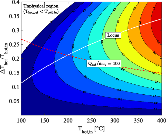
Figure 2. Effect of heat-source cooling and heat-sink heating on ideal maximum cycle power output per unit heat-capacity rate showing locus of maximum net output power, with Tcold,in = 20°C.
Assuming that the two heat exchangers (HHX and CHX) are ideal with no losses to the surroundings, the enthalpy difference across the HHX is equal to the heat transferred to the working fluid in all of the cycles, . Note that this analysis is subtly different from a conventional maximum work (exergy) analysis, in which heat is rejected from a similar arrangement to a constant “dead” state temperature, rather than to a varying cooling stream temperature as is done here.
The horizontal axis in Figure 2 is the inlet temperature of the heat-source fluid stream to the HHX, Thot,in, while the vertical axis is the (fractional) temperature drop of the same stream through the HHX normalized by the inlet temperature, ΔThot/Thot,in. The inlet temperature of the heat-sink fluid stream to the CHX is set to Tcold,in = 20°C. Also superimposed on this plot are two lines. The white line is a locus of the maximum power output at each value of Thot,in, which corresponds to a monotonically increasing value of ΔThot/Thot,in that obeys the relationship 1–(Thot,in/Tcold,in)0.5. The red line traces the output of this ideal arrangement for a given application with a fixed heat flow rate, and a fixed heat-capacity rate, . This case has a fixed heat flow per unit heat capacity, chosen here arbitrarily to be equal to 100.
Two important interpretations emerge from Figure 2. First, the ideal conversion of heat at higher temperatures such that maximum power is extracted requires that the normalized heat-source temperature drop is high. For instance, consider an ideal system to be used for converting heat at Thot,in = 100°C. For this system, maximum power is attained for a normalized heat-source temperature drop of ΔThot/Thot,in = 0.11. This corresponds to a temperature drop of ΔThot = 42°C, from 100 to 58°C through the HHX. At the same time (not shown in the figure) the cold temperature through the CHX increases by 38°C from 20 to 58°C. Conversely, consider a second system to be used for converting heat at Thot,in = 400°C. Maximum power for this second system is attained for a normalized heat-source temperature drop of ΔThot/Thot,in = 0.34, which corresponds to a temperature drop of ΔThot = 230°C, from 400 to 170°C. The cold temperature though the CHX increases by 150°C from 20 to by 170°C.
Now, for a given heat-capacity rate of the heat-source and sink fluid-streams the second system will be more than 5 times larger in terms of the heat input to the cycle and, thanks to its higher efficiency, almost 10 times larger in terms of the power output. In other words, for the same heat-source fluid-stream heat capacity rate, larger-scale (centralized) plants are better suited to the effective utilization of higher temperature heat-sources, whereas smaller-scale (distributed) systems are more appropriate in optimally converting lower-temperature sources. The increased stream heat capacity rates expected in the larger-scale systems will only act to amplify this distinction.
Secondly, an important difference between the employment of steam/water and organic compounds as working fluids (i.e., between conventional steam-Rankine cycles and ORCs) is the much greater specific enthalpy associated with phase change of the former. An increased specific enthalpy associated with heat addition will lead to an increased heat (per unit mass of working fluid) intake into the cycle, shifting the ideal operation of this cycle toward higher temperatures and larger systems as a consequence of the discussion in the previous paragraphs. It is also true that the specific power output from Rankine cycles, even at low temperatures, can be higher than ORC equivalents. However, this advantage is overcome and negated by the need to use much lower working fluid mass flow rates in Rankine cycles operating at low temperatures compared to ORCs, owing to the large differences in specific enthalpy of heat addition.
Cost Considerations
An acceptable performance from a technical standpoint can be judged based on indicators, such as primary energy/fuel efficiency, emissions, flexibility of operation, and ability to match variable demand. Yet, beyond these purely technical considerations, the widespread deployment of any successful solution to the energy challenge must be associated with, either a cost benefit or at the very least a cost level that is affordable and economically justifiable to the end-user or investor (Markides, 2013).
In conventional power generation, fuel costs are the single largest contributor toward the total cost of electricity. Consider, for example, a typical coal-fired steam power plant with a typical efficiency of 38–40%, a capital cost in the region of ~$1,300/kW, an additional operating and maintenance cost of $30–45/kW, and an economic life expectancy of 30 years (Royal Academy of Engineering, 2004). This plant has a total LEC of $50/MWh produced over the lifetime of the plant. Moreover, the largest single contributor toward this cost is the cost of fuel, which amounts to 35%. The case is even stronger for gas-fired power plants. A typical simple open-cycle gas turbine power plant with a typical efficiency of 39–43%, a capital cost of $510/kW, an operating and maintenance cost of $55/kW, and an economic life expectancy of 20 years has a total LEC of $55/MWh of which >60% is attributed to the fuel. Similarly, closed-cycle combined gas turbine power plant with a typical efficiency of 58–60%, a capital cost of $470/kW, an operating and maintenance cost of $40/kW, and an economic life expectancy of 25 years has a total LEC of $55/MWh of which 60% is again attributed to the purchase of gas (Royal Academy of Engineering, 2004).
Hence, beyond its formal definition, it is reasonable to argue that, for the case of conventional power generation, the thermal efficiency is also a figure-of-merit that is a reasonable measure of the electrical-energy output (and thus profit) per unit total cost. This cannot be said, however, for power-generation systems whose energy input is not associated with a significant operating cost, such as solar heat (as well as geothermal energy and waste heat). In this case, the total cost is dominated by the up-front initial investment required for the necessary capital expenditure, and consequently, the figure-of-merit that is the electrical-energy output (i.e., profit) per unit total cost must be evaluated directly as the electrical-energy output per unit installation cost, or at least per unit capital cost. In both cases, this figure-of-merit goes some way toward reflecting the true economic viability of such systems, in a way that thermal efficiency alone cannot.
Distributed Energy-Conversion Systems
In the previous sections, a brief overview was given of the considerations that are acting to motivate an interest in technologies that are capable of converting solar heat to useful work (either mechanical, hydraulic, or electrical). Additionally, some of these technologies are diverse enough to be suitable for the conversion of other renewable energy sources such as geothermal heat and biomass/biogas, as well as waste heat in a variety of settings.
These technologies are being proposed, in particular, for distributed power generation (and/or simultaneous heat/cooling provision). Benefits from an increased deployment of distributed power-generation solutions include enhanced reliability and security, reduced losses from energy transmission and distribution, as well as reduced infrastructure and maintenance costs for transmission and distribution, and easier plant sizing (Gullì, 2006; Strachan and Farrell, 2006).
It is implied that distributed systems will be smaller in scale than centralized equivalents and will not benefit from the economies of scale the latter enjoy. One must also remain aware of the fact that centralized, larger-scale systems will retain an edge in plant efficiency, but that this efficiency will be compromised by increased transmission/distribution losses from the plant to the consumer/end-user. In many cases, these losses are not negligible, amounting to an efficiency reduction of 5–10% points.
Organic Rankine Cycles
Technology Overview
ORC systems have been indicated in the previous sections as a highly appropriate technology for the conversion of heat at temperatures <400°C. ORCs with suitable working fluids can be used at higher temperatures, but we will focus on this temperature range in the present paper. ORCs are a relatively mature technology, with operational experience available since the 1960s. Currently, more than 600 ORC plants are in operation worldwide, with a cumulative capacity in excess of 2,000 MW.
A number of excellent reviews of all types of ORC systems are available in the literature (Chen et al., 2010; Lecompte et al., 2015). In particular, a number of groups including those at the University of Liege and the Agricultural University of Athens (Orosz et al., 2009; Tchanche et al., 2009, 2010, 2011; Delgado-Torres and García-Rodríguez, 2010; Malavolta et al., 2010; Kosmadakis et al., 2011; Declaye et al., 2012) have considered ORC systems specifically in solar applications in a series of noteworthy studies that include installing and testing solar-ORC systems. The present paper focuses on the most advanced in terms of development/readiness and lowest-cost system, the sub-critical ORC without regeneration. A simple sub-critical, non-regenerative ORC system is shown in Figure 3, along with a cycle on a T–S diagram with R-245fa as the working fluid.
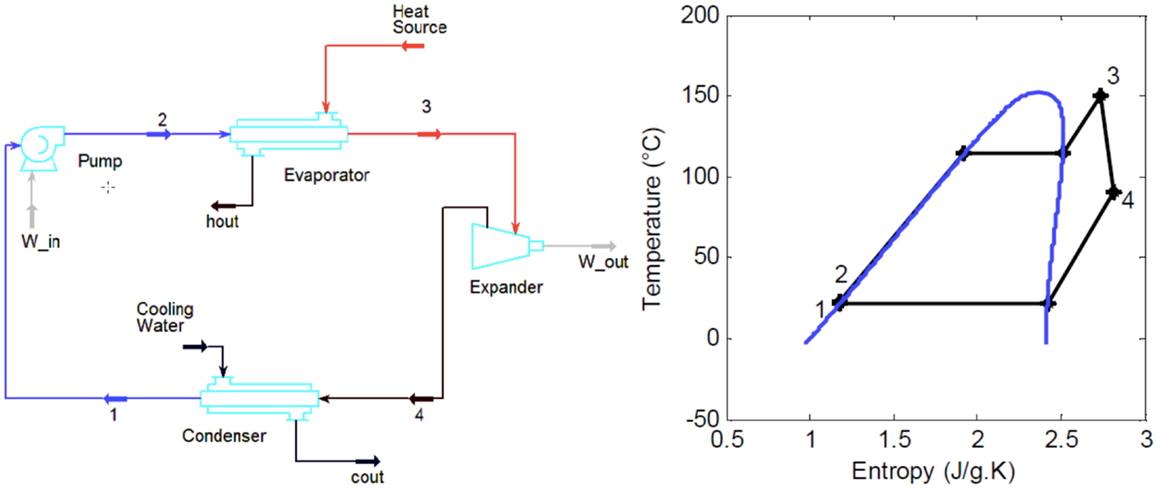
Figure 3. Typical sub-critical non-regenerative ORC system layout and cycle on a T–S diagram with pure R-245fa as the working fluid.
The main components of the system in Figure 3 are a feed pump (this can be multistage), evaporator (this can comprise a number of components, including a superheater), expander/turbine (again this can comprise a number of stages) and condenser (including a desuperheater). A regenerator can also be used to recover some of the heat-rejected downstream of the expander (Point 4 in the diagram) and to use this to perform part of the heating downstream of the pump (Point 2).
As mentioned in Section “Rankine Cycle Ideal Maximum Power,” ORCs are associated with a number of specific advantageous features compared to water/steam-Rankine cycles. First, unlike wet fluids, such as water, dry and isentropic organic fluids (see Figure 4) have positively sloped or vertical dry saturation curves. Therefore, they do not require a significant degree of superheating to avoid condensation and droplet formation in turbines/expanders. Such a scenario can cause mechanical damage to the turbine blades and also degrade the thermodynamic performance of this component. The former would not apply to more structurally robust expander designs (e.g., reciprocating piston expanders), but the latter would remain.
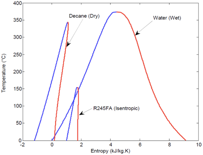
Figure 4. Saturation (phase equilibrium) curves for dry, wet, and isentropic fluids on a T–S diagram.
In the case of wet working fluids, the desire to keep the flow through the expander/turbine outside of the saturation region over the entire expansion process, and hence for the exit state from this process to also be outside the saturation region, translates to a requirement for significant superheating prior to entry into the turbine. The absence of adequate superheating leads to an intersection of the dry saturation curve during expansion, and thus, expansion into the saturation (two-phase) region.
Second, it is advantageous thermodynamically to expand the working fluid to the lowest possible pressure, which corresponds to condensation and heat rejection at a temperature as close as possible to the cooling stream temperature. Assuming this is at ambient conditions (20–25°C), the condensation temperature would be a few degrees higher than this, as determined by the pinch temperature difference in the condenser. For water, a saturation temperature of 30°C corresponds to an absolute saturation pressure close to 0.04 bar. The large pressure difference between the surrounding atmosphere and any components that operate at such low pressures can lead to ingress of air into the cycle with significant detrimental effects on system performance. The design of components that can operate reliably at such a degree of sub-atmospheric pressures is difficult and expensive. Conversely, for R-245fa, the saturated condensation pressure at a saturated temperature of 30°C is 1.8 bar, which is above atmospheric.
Furthermore, it can be said that, in general, the large choice of currently available (and possible future) organic compounds that can be used as working fluids, and mixtures thereof, allows ORCs to be “tuned” to specific applications. Therefore, ORCs comprise a more flexible solution by allowing some degree of control over the phase behavior of the working fluid, the design of the processes that comprise the cycle, and in matching the cycle to available heat sources and heat sinks.
Direct Performance Comparison with Steam-Rankine Cycles
When discussing Figure 2, a rudimentary analysis was used to indicate the underlying reasons for which ORCs may outperform conventional Rankine cycles when converting low-grade heat in small-scale systems. The current section proceeds to compare these two cycles directly and to offer further insight into their relative performance, and also, the approximate cost of related power-generation systems. Specifically, we focus here on case-study application where it is desired to generate electrical power from a fluid stream at an initial temperature of Thot,in = 200°C. The heat-source fluid stream is allowed to interact thermally with the heat engine, such that its enthalpy (and thus temperature) will decrease progressively as heat is taken in the cycle. This is similar to the rudimentary analysis that led to the result in Figure 2, only that analysis considered a series of multiple ideal cycles, i.e., fully reversible, Carnot cycles, whereas here the cycle is a single theoretical Rankine cycle with either a water or an organic compound as the working fluid. The heat-source fluid stream is taken to have a mass flow rate and a specific heat capacity cp,hot = 1 kJ/kg K, such that the stream heat capacity duty is . The heat-sink (cooling) fluid stream is assumed to be (constant) at an ambient temperature of 20°C, while the condensation temperature and temperature at the inlet of the pump, T1, is taken to be 10°C higher than this, T1 = 30°C.
Figures 5 and 6 show the specific work output and thermal efficiency, respectively, for a number of Rankine cycles operating with water and fluid R-245fa. Three lines are shown on each plot. Each one of these corresponds to a different saturation temperature (and thus also a different saturation pressure) during evaporation, as per the legend. Results for water/steam-Rankine cycles are shown for the case of expansion to and condensation at: (i) 1 bar and 100°C, and (ii) 0.04 bar and 30°C.
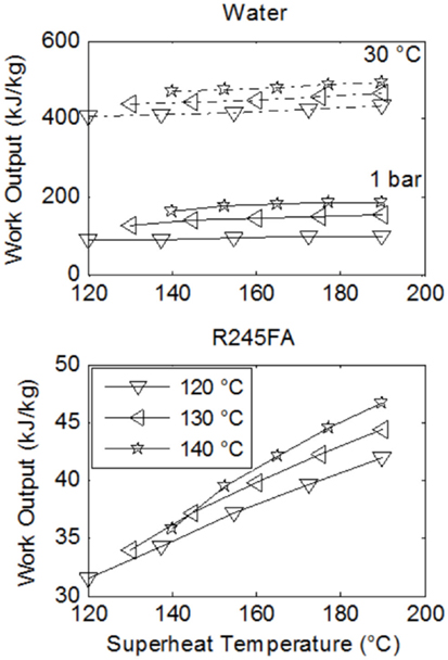
Figure 5. Comparison of specific work output, or power output per unit working fluid mass flow rate, from Rankine cycles with water and R-245fa over a range of maximum cycle temperatures, T3, which from Figure 3 are found between the evaporator and the expander. The heat-source fluid stream has an initial temperature Thot,in = 200°C, a mass flow rate and a specific heat capacity cp,hot = 1 kJ/kg K. The three lines correspond to different evaporation (saturation) temperatures, given in the legend. Water results are shown for expansion down to (and condensation at) 1 bar/100°C and 0.04 bar/30°C.
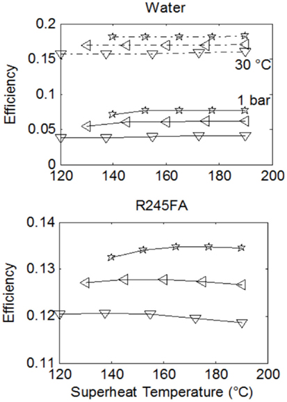
Figure 6. Comparison of cycle thermal efficiencies from Rankine cycles with water and R-245fa over a range of maximum cycle temperatures, T3. Results correspond to the same conditions given in Figure 5.
Clearly, it is thermodynamically beneficial to expand to a low temperature that is as close as possible to atmospheric temperature, which in this case is 30°C. However, this may come at a severe cost especially for small-scale systems, as discussed previously. Hence, expansion to near atmospheric pressure is also shown. Expansion to the lower temperature leads to a 2.5–4-fold increase in both specific work output and thermal efficiency.
In Figures 5 and 6, better performance (specific work and efficiency) can be observed at higher evaporation pressures. The extent of superheating does not strongly affect water-based cycle performance but has a significant effect on work output from the ORCs, even though this does not appear in the ORC efficiencies. Essentially this is due to a near-proportional increase in both the heat input to the cycle along with the specific work output, as the degree of superheating is increased.
When comparing the working fluids, it is found that water outperforms the organic fluids with respect to specific work output by a factor of between two and five at the higher condensation pressure and temperature (for water). This increases to a factor of 10 or more at the lower condensation pressure and temperature. Although the specific work potential of the steam-cycles is clearly higher than the equivalent potential of the organic-fluid cycles, the performance in terms of efficiency presents a more mixed picture. In fact, at the higher condensation pressure and temperature for water, the organic fluids outperform water by a factor of 2–3, while at its lower condensation pressure and temperature water outperforms the organic fluids only marginally, by 3–4% absolute points, or 25–30% in relative terms.
Therefore, if one is to accept that it is not economically desirable to design a system in which steam is expanded down to and condenses at pressures of 0.04 bar, which is a reasonable point of view for affordable, distributed, and small-scale power generation, ORCs show a potential for improved performance compared to conventional (steam) Rankine cycles in terms of efficiency. Furthermore, it is important to consider not only the specific work output of these cycles, but the actual power output once the mass flow rate of the working fluid is evaluated based on the thermal interaction between the heat-engine cycle and the external heat-source fluid stream. The result from such a consideration is shown in Figure 7, where we include data from three organic fluids: Butane, R-245fa, and Perflenapent.
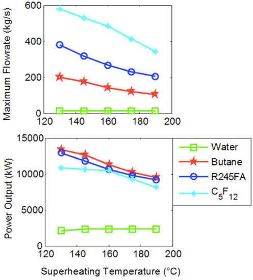
Figure 7. Maximum working fluid mass flow rate and total power output from Rankine cycles with water and indicated organic fluids over a range of maximum cycle temperatures, T3. Results correspond to the same conditions given in Figures 5 and 6. Water results are shown only for expansion down to (and condensation at) 1 bar/100°C.
The results in Figure 7 were generated by progressively increasing the mass flow rate of the working fluid in each cycle (i.e., each point on this plot) until a pinch temperature difference of 10°C was reached in the evaporator between the heat-source stream and the working fluid for that cycle. This is the maximum working fluid mass flow rate. Interestingly, superheating is detrimental to ORC power output, but not to water. This figure demonstrates that, at least theoretically, organic fluids have the potential to outperform water by a considerable extent, also when considering power output in the chosen case study. In particular, power output for R-245fa is higher than that for water by a factor of 4–5. It is emphasized that this figure does not show water data at the low condensation conditions (0.04 bar and 30°C). Nevertheless, the underlying conclusion remains unchanged, even when this data are considered. The organic fluids in this case outperform water by a factor between 1.5 and 2.
The observation that organic working fluids have (desirably) higher power outputs than water, even when compared to water condensing at the lower pressures and temperatures that showed much higher specific work outputs (per unit mass flow rate of working fluid) by more than an order of magnitude (refer back to Figure 5), can be understood by the much higher mass flow rates permitted in the ORCs before any pinch violation is reached. This can also be seen directly in Figure 7 and arises from the significantly higher specific enthalpy change during heat addition for water/steam compared to that of the organic fluids, as indicated in Figure 4.
In Figure 8, a basic attempt is made at estimating approximate system costs. Here, we show the sum of costs associated with the purchase of the four basic components that form the Rankine heat-engine systems. Each data point corresponds to the same systems contained in Figure 7. Heat exchanger costs were evaluated by using the C-value method, while costs for the pumps and expanders were obtained by compiling price information from a market study and establishing a correlation with component power, pressure ratio, and flow rate (Oyewunmi et al., 2014, 2015). The C-value method is an approximate approach for the costing of heat exchangers, described in Hewitt et al. (1994).
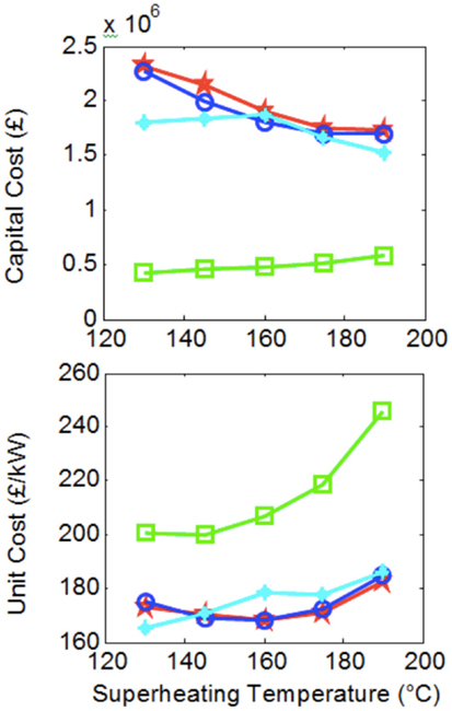
Figure 8. System costs corresponding to Figure 7, over a range of maximum cycle temperatures, T3.
Figure 8 shows that, due to their larger heat exchangers (allowing higher power outputs) ORCs are more expensive when considering the total system costs compared to steam-Rankine cycles. However, when the cost of the system is normalized by the power output capacity of the system, thus providing the all-important indicator of cost per unit useful output, the ORCs are shown to be a more affordable solution.
Finally, it is possible and instructive to condense the information contained in Figures 6–8 into a single performance-cost map. This is attempted in Figure 9. For simplicity and clarity, we do not show all data corresponding to each working fluid in this figure, which can be done by drawing an area for each working fluid. Instead, we select a single degree of superheating that corresponds to the maximum total power output. We recall, from Figure 7, that for organic fluids this is attained with little or no superheating. So, for example, for R-245fa, this would be at an evaporation temperature of 120°C, when the power output is ~14 MW and the cost per unit power ~£195/kW (or $300/kW).
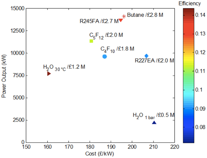
Figure 9. Consolidated plot of power output, efficiency and cost from Rankine cycles with water and indicated organic fluids corresponding to the results contained in Figures 6–8.
Opportunities for Improvement and Future Developments
It is known from second law (exergy) analyses that about 75–80% of the ultimate potential to do useful work in a sub-critical ORC is lost in the heat exchangers (evaporator, condenser and regenerator) and about 20–25% in the expansion machine. The lost work (exergy destruction) in the evaporator amounts to ~1.5:1–2:1 times that lost in the condenser (Freeman et al., 2015b). Hence, significant performance improvements can come from advances in these areas or components. Additionally, there is a great interest in the identification of optimal working fluids for specific applications, and attention has turned to the possible employment of binary and even tertiary mixtures of organic compounds as working fluids in ORCs (as mentioned in Section “Heat Exchanger Thermodynamic Performance Versus Size/Cost”). This is an area of active research, and a challenge arises in predicting reliably the properties of these fluids.
Advanced ORC system models that include a computer-aided molecular design (CAMD) framework with explicit information on the role of molecular size and structure on thermodynamic and thermal properties of working fluids are also currently in development (Lampe et al., 2012), based on thermodynamic theories such as the statistical-associated fluid theory (Lampe et al., 2012; Oyewunmi et al., 2014, 2015). Such models will play an important role in identifying optimal compromises between thermodynamic and thermal performance, which controls efficiency, power output, system size, and cost.
Finally, at the scales of operation of interest, the selection of the expansion machine is an open question, with positive-displacement expanders presenting a real challenge to turbomachines. A significant effort is being made in the modeling and development of ORC systems featuring positive-displacement expanders, which promise higher efficiencies, for the applications identified in the present paper.
Finite Heat Transfer Effects
Heat Exchanger Thermodynamic Performance Versus Size/Cost
Recently, the selection of working fluids for ORC systems has received close attention from the ORC community, including a particular interest in multicomponent fluid mixtures, due to the opportunities they offer in improving thermodynamic performance. Various authors have carried out investigations to demonstrate and quantify these benefits, which have shown that working-fluid mixtures can exhibit an improved thermal match with the heat source compared to the isothermal profile of (isobaric) evaporation of pure-component fluids, therefore reducing exergy losses due to heat transfer, and increasing thermal and exergy efficiencies (Angelino and di Paliano, 1998; Wang et al., 2010; Garg et al., 2013).
Investigators have carried out both experimental and theoretical studies across a range of heat-source temperatures into the benefits of employing working-fluid mixtures based on refrigerants (Sami, 2010; Chen et al., 2011; Aghahosseini and Dincer, 2013), hydrocarbons (Heberle et al., 2012; Shu et al., 2014), and siloxanes (Dong et al., 2014). Compared to pure fluids, binary mixtures showed increased power outputs by up to 30% and thermal efficiencies by >15% in some cases. Excellent second law analyses have also shown significant potential benefits (Lecompte et al., 2014). [Some exceptions to these general trends have also been reported (Li et al., 2014).]
Additionally, fluid mixtures can be used to adjust the environmental and safety-related properties of ORC working fluids or to improve design parameters of system components; this is increasingly of importance. At the same time, some investigators have begun to develop and apply advanced CAMD methodologies (Papadopoulos et al., 2010; Lampe et al., 2014) with a view toward identifying or designing optimal fluids for ORC systems.
While these efforts have demonstrated the potential thermodynamic advantages of working-fluid mixtures, notably in terms of power output and efficiency, many of the associated conclusions have been derived strictly based on the thermodynamic cycle analyses that do not fully consider the expected heat transfer performance between the heat-source/sink and working-fluid streams in the heat exchangers of ORC engines. In particular, the heat transfer and cost implications of using working-fluid mixtures have not been properly addressed. Essentially this arises from the minimization of the temperature differences between the working fluid stream (cycle) and the heat-source/sink streams on the other side of the heat exchange components. This practice is thermodynamically beneficial, but detrimental in terms of heat transfer, and it opens up an important area of research aiming to enhance heat transfer with low-cost modifications across small temperature differences. Moreover, refrigerant mixtures are known to exhibit reduced heat transfer coefficients compared to their pure counterparts (Jung et al., 1989). Specifically, heat transfer coefficients for refrigerants mixtures are usually lower than the ideal values, linearly interpolated between the mixture components. This may invariably lead to larger and more expensive heat exchangers in an ORC system that employs a working-fluid mixture. Therefore, although working-fluid mixtures may allow a thermodynamic advantage over single-component working fluids, they may also lead to higher system costs owing to a deterioration in their thermal performance.
Recent analyses (Oyewunmi and Markides, 2015; Oyewunmi et al., 2015) have revealed that the temperature glides of the working-fluid mixtures during evaporation and condensation can result in higher power output and thermal/exergy efficiencies for fluid mixtures (at least for the two sets of mixtures in the specific cases studied). The pure fluids did however result in smaller expanders due to their lower volumetric flow rates and expansion ratios and also smaller evaporators and condensers, requiring less expensive components than the fluid mixtures. Therefore, although the mixtures were found to have the highest power output, they also had the highest rated costs (equipment cost per kW of power generated), which resulted from larger equipment/component sizes compared to the constituent pure fluids.
These observations imply that the thermodynamic benefits derived from using working-fluid mixtures may be outweighed by the increased costs incurred, although this is in need of confirmation and generalization. The fact that these insights were only possible from a direct consideration of thermal and cost factors as exemplified here, underlines the importance of employing a combined thermodynamic, thermal, and cost approach in the selection of optimal working-fluid (mixtures) for ORC systems.
Thermally Induced Thermodynamic Losses
Time-mean heat transfer can act to affect heat-engine performance detrimentally by giving rise a direct loss of the available heat from the heat source to the surroundings, which does not then take part in the thermodynamic cycle. This can be alleviated by careful design of the relevant components, for example, by insulating the components and/or by separating hot and cold sections in order to force thermal-energy transport into the working fluid cycle. Beyond these losses, situations arise in which unsteady heat transfer (even in the case that the time-averaged heat transfer is zero) plays a significant role in affecting the performance of the energy-conversion systems under consideration, as well as of similar systems. This is the case in positive-displacement expansion machines that are being envisioned as high efficiency alternatives to turbomachines when used in small-scale ORC systems (but also, as an side, in the heat exchangers and in the nominally adiabatic vapor volumes of TFOs, such as the NIFTE).
Some peculiarities arise with respect to unsteady heat transfer in these systems owing to the fact that, unlike time-mean heat transfer, it is not possible to arbitrarily minimize this component of heat transfer with increasing levels of insulation due to a thin solid region (known as the thermal diffusion length or “penetration depth”) that is in thermal contact with and experiencing time-varying heat exchange with the fluid domain. This region will interact thermally with the fluid in a time-varying manner and affect the magnitude and phase of the heat transfer process. This unsteady thermal process and its detrimental effect on thermodynamic performance (also in the absence of time-mean heat transfer) are dealt with in the following sections.
Unsteady and Conjugate Heat Transfer
Unsteady and conjugate heat transfer is defined as a time-varying thermal-energy transport process in which a solid is in thermal contact with a fluid, with both domains exhibiting a time-varying temperature and heat flux at their common boundary, i.e., the solid–fluid interface. Figure 10 shows a conjugation map for a one-dimensional thermal interaction between a solid of finite thickness a and a fluid within which a flow imposes a constant convective heat transfer coefficient h. This map is plotted as a function of the unsteady Biot number, Bu = hδ/ks, where the relevant length scale in the solid is the thermal penetration depth or diffusion length δ = (αsτ/π)0.5 that takes part in the unsteady thermal process rather than the full extent/thickness of the solid domain a, and the Fourier number, Fo = αsτ/a2. It is noted that the unsteady Biot number Bu is related to the conventional steady Biot number Bi via the dimensionless length scale a* = a/δs, such that Bu = Bi/a*. In these definitions, ks is the thermal conductivity of the solid, αs is the thermal diffusivity of the solid, and τ is the period of the temperature oscillations in the fluid domain due to some time-varying (periodic) thermodynamic process.
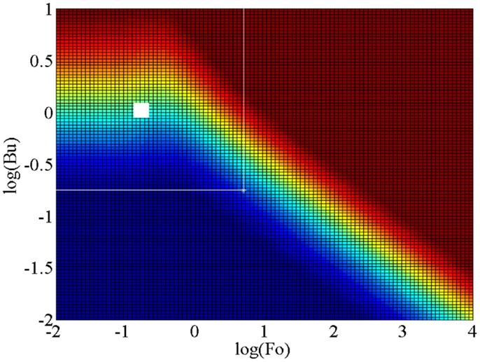
Figure 10. Map of conjugation in Fo–Bu space, showing the extent of conjugation in unsteady 1D solid–fluid systems, with an isoflux outer wall boundary condition. Red indicates large temperature fluctuations and small heat-flux fluctuations (approaching an isoflux boundary condition) on the inner wall surface at the (wetted) solid–fluid interface, and blue indicates large heat-flux fluctuations and small temperature fluctuations on the inner wall surface (approaching an isothermal boundary condition).
The red region in Figure 10 indicates large temperature fluctuations and small heat-flux fluctuations (i.e., an isoflux boundary condition) on the (inner) solid–fluid interface, whereas the blue region indicates large heat-flux fluctuations and small temperature fluctuations on the same interface (i.e., an isothermal boundary condition). Since data from ORC expanders are not available, the large white square is an approximate narrow area occupied by the NIFTE prototype water-pump TFO as reported in Smith (2006), and the extended white space is the estimated design area within which the TFO technology is expected to be found given reasonable variations from the initial design (Markides and Smith, 2011; Glushenkov et al., 2012; Solanki et al., 2012, 2013a,b; Markides and Gupta, 2013; Markides et al., 2013, 2014; Palanisamy et al., 2015).
It is evident that the region of interest straddles the two extreme cases defined above. This implies that the boundary condition on the working fluid is neither isothermal nor isoflux, and that the solid and fluid are thermally coupled in such a way that in order to predict the temperature and heat flux at the solid–fluid interface the heat transfer problem must be solved in both domains and the solutions matched at this interface. This observation is important and has serious implications because it suggests that any effort to understand and predict the unsteady thermal losses in such a device must contain explicit information not just on the thermal processes in the fluid (i.e., heat transfer coefficients), but also in the solid which actively takes part in determining the thermal solution.
Thermodynamic Losses in Gas Springs
Mathie et al. (2014) also considered the thermodynamic losses that result from cyclic, unsteady conjugate heat transfer in reciprocating components termed “gas springs.” A gas spring is simplified model of a reciprocating compressor or expander, in which a fixed mass of gas is trapped in a cylinder, with a piston acting to impose volumetric variations. In the case considered in Mathie et al. (2014), the variations where sinusoidal, V(t) = Vo + Va sin ωt, with a varying frequency, ω, whose dimensionless description is the Péclet number, Pe = ωD2/αf, where D is the diameter of the cylinder, and αf is the thermal diffusivity of the fluid (gas). This arrangement is a convenient way to isolate the thermodynamic irreversibility due to thermal processes and remove those due to valve (pressure) losses. In addition to the frequency of the reciprocating motion, the framework allowed variations to the thickness and thermal properties of the solid walls of the cylinder, which are captured by the normalized cylinder wall thicknesses, a* = a/δ, where δ = (2αs/ω)0.5 is the thermal penetration depth.
A result from the investigation in Mathie et al. (2014) is shown in Figure 11, which indicates the ability of the solid domain variables to affect the thermodynamic loss. It is clear that the effect of the solid can be significant, depending on the solid and gas material properties (thermal conductivity, density, specific heat capacity), and also that mid-speed (intermediate Pe) constitutes the worse-case scenario for this type of loss mechanism, which can be close to 20% of the work exchanged with the gas spring for these conditions.
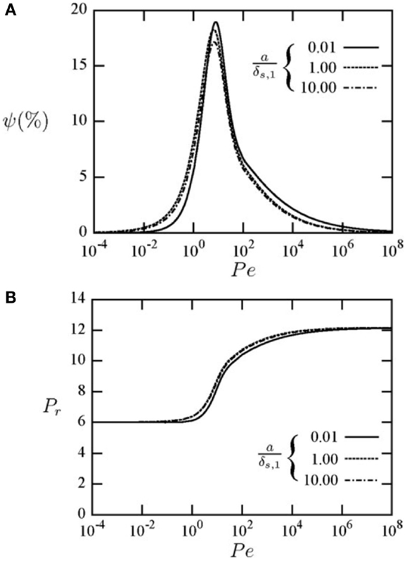
Figure 11. (A) Thermodynamic loss due to finite unsteady heat transfer, ψ, and (B) pressure ratio, in a reciprocating gas spring with a volumetric compression ratio of six, a (solid-to-fluid) thermal conductivity ratio of 1.06, density ratio of 145.1 and specific heat capacity ratio of 0.15, and for different normalized cylinder wall thicknesses, a/δ as shown in the legend, as a function of Péclet number, Pe. Reproduced with permission from Mathie et al. (2014).
Non-Linear Heat Transfer Augmentation
Section “Thermodynamic Losses in Gas Springs” considered the effects of unsteady and conjugate heat transfer for the case that the heat transfer coefficient, h, is set to a constant (but complex) value. This is the conventional approach taken when dealing with gas-spring problems, in order to account for the observed phase shift between the heat flux at the wall, that arises from the thermal boundary layer there, and the temperature difference across the (bulk) fluid (Mathie and Markides, 2013; Mathie et al., 2013, 2014). One additional phenomenon is suspected to take place in the systems of interest, which is due to a non-linear interaction between the (time-varying) heat transfer coefficient, h, and the (time-varying) temperature difference across the fluid domain, ΔT. This phenomenon is referred to as “heat transfer augmentation” (Mathie and Markides, 2013; Mathie et al., 2013).
Mathematically, heat transfer augmentation can be described as follows; consider a fluid undergoing a time-varying thermal and fluid-flow process, such that and using Reynolds decompositions of a fluctuation around a mean. Then, the time-mean heat flux is given by the expression . Essentially, this equation for the time-mean heat flux states that the fluctuations of the heat transfer coefficient, h′(t), and those of the temperature difference, ΔT′(t), can become non-linearly coupled. Physically, we would expect an instantaneous increase in the heat transfer coefficient to give rise to a decrease in the instantaneous temperature difference, and vice versa.
Figures 12 and 13 show results from a semi-analytical study on the augmentation ratio, A, as a function of the: (i) heat transfer coefficient fluctuation intensity, h* = ha/ho, where the sinusoidally varying heat transfer coefficient is: h(t) = ho + ha sin ωt, (ii) Biot number, Bi = ho a/k, and (iii) the normalized solid wall thicknesses, a* = a/δ, where δ = (2αs/ω)0.5 is the thermal penetration depth (Mathie and Markides, 2013). Note that in Figure 12A the normalized solid wall thickness is kept constant at a* = 1, whereas in Figure 12B the Biot number is kept constant at Bi = 1. It can be observed that the augmentation ratio is always A ≤ 1, suggesting a reduction in time-mean heat transfer relative to expectations from . Importantly, at small a*, large h*, and/or large Bi, this effect can become very significant.
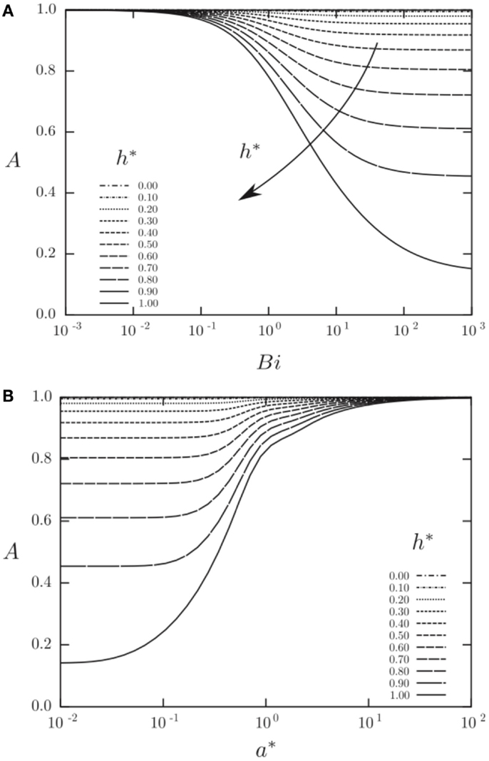
Figure 12. Augmentation ratio, , in a planar 1-D convective-conductive domain with an isoflux outer boundary condition as a function of heat transfer coefficient fluctuation intensity (h* = ha/ho; where the sinusoidally varying heat transfer coefficient is: h(t) = ho + ha sin ωt), Biot number (Bi = ho a/k) and Fourier number (a* = a/δ = π0.5/Fo0.5). Reproduced with permission from Mathie and Markides (2013).
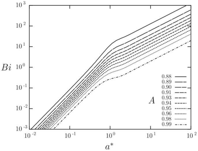
Figure 13. Combination of the augmentation plots in Figure 12 into a single map. Reproduced with permission from Mathie and Markides (2013).
The role of this phenomenon has not yet being considered in the energy-conversion systems under consideration, but it has been identified and measured in a number of flows, such as in Mathie and Markides (2013) and Mathie et al. (2013) which deal with two such cases: (i) the unsteady heat transfer between low-dimensional falling films and heated substrates and (ii) the unsteady heat transfer between downstream of a broadband (turbulent) backwards-facing step. This forms an interesting and important avenue for further work.
Further Discussion and Conclusion
This paper has been concerned with energy technologies capable of converting solar heat from non-concentrated or low-concentration solar collectors at temperatures <400°C to useful power, aimed at the domestic (1–10 kWe) and commercial/industrial (10–100 s of kW) sectors, thus covering a range of power output scales from a 1 kW to 1 MW. The availability of solar energy is strongly dependent on geography and also exhibits strong diurnal and possibly also seasonal variations. These latter variations of solar intensity depend on geography and in some cases are mild but in others quite strong. The solar resource, and therefore the potential availability of heat and power from combined solar-energy systems, such as PVT and S-CHP technologies, must also be considered in conjunction with end-user needs in energy consumption. Northern European climates, the UK for example, are less favorable for these technologies, even excluding climatic conditions (cloud coverage). The daily load factor varies strongly between summer and winter, with the peak demand at 6 p.m. in January when solar intensity is almost zero. Therefore, solar electricity will require significant storage to be effective and for this reason it will be considerably more expensive than predictions in generic LEC studies that are based in more favorable geographic locations. This plays to the strengths of small-scale thermodynamic power-generation (S-CHP) systems, which can benefit directly from TES as a part of their operation, relative to PV.
Such systems were considered based on thermodynamic vapor-phase heat-engine cycles undergone by organic working fluids, namely ORCs. ORCs are a relatively well-established and mature technology compared to some of the aforementioned alternative technologies, such as the TFOs, which have not yet found technological maturity and commercial application to the extent that ORC systems have, with high efficiencies especially when used with higher temperatures heat sources and at larger scales. Specifically, ORC systems are particularly well-suited to the conversion of low-to-medium-grade heat to mechanical or electrical work, and at an output power scale from kilowatts up to a few 10s of megawatts. Thermal efficiencies in excess of 25% are achievable at higher temperatures (i.e., with heat-source temperatures up to about 300–400°C), and efforts are currently in progress to develop improved systems by focusing on working fluid selection, the heat exchangers, and expansion machines at the scale of interest.
Models capable of accurate and reliable predictions of system performance were used to provide insight on operational characteristics and performance. Challenges and opportunities were identified, and recommendations made for further improvements, in particular with regards to the minimization of thermodynamic losses inflicted by finite heat transfer effects. It was noted, beyond conventional loss mechanisms, that losses can arise from inherently unsteady, conjugate and non-linear thermal processes and interactions between the working fluids within the systems of interest and the solid walls of key system components.
Conflict of Interest Statement
The author declares that the research was conducted in the absence of any commercial or financial relationships that could be construed as a potential conflict of interest.
Acknowledgments
The author would like to thank O. A. Oyewunmi for generating some of the results contained in the paper, as well as the following members of the CEP group: R. Mathie, I. Zadrazil, A. Charogiannis, R. Edwards, J. Freeman, A. I. Taleb, I. Guarracino, and C. Kirmse, without whom this work would not have been possible; it has been a pleasure and a privilege to work with them.
References
Aghahosseini, S., and Dincer, I. (2013). Comparative performance analysis of low-temperature organic Rankine cycle (ORC) using pure and zeotropic working fluids. Appl. Therm. Eng. 54, 35–42. doi:10.1016/j.applthermaleng.2013.01.028
Ajimotokan, H. A., and Sher, I. (2015). Thermodynamic performance simulation and design optimisation of trilateral-cycle engines for waste heat recovery-to-power generation. Appl. Energy 154, 26–34. doi:10.1016/j.apenergy.2015.04.095
Angelino, G., and di Paliano, P. C. (1998). Multicomponent working fluids for ORCs. Energy 23, 449–463. doi:10.1016/S0360-5442(98)00009-7
Backhaus, S., and Swift, G. W. (2000). A thermoacoustic-stirling heat engine: Detailed study. J. Acoust. Soc. Am. 107, 3148–3166. doi:10.1121/1.429343
Bianchi, M., and Pascale, A. D. (2011). Bottoming cycles for electric energy generation: Parametric investigation of available and innovative solutions for the exploitation of low and medium temperature heat sources. Appl. Energy 88, 1500–1509. doi:10.1016/j.apenergy.2010.11.013
Biswas, K., He, J., Blum, I. D., Wu, C.-I., Hogan, T. P., Seidman, D. N., et al. (2012). High-performance bulk thermoelectrics with all-scale hierarchical architectures. Nature 489, 414–418. doi:10.1038/nature11439
Chen, H., Goswami, D. Y., Rahman, M. M., and Stefanakos, E. K. (2011). A supercritical Rankine cycle using zeotropic mixture working fluids for the conversion of low-grade heat into power. Energy 36, 549–555. doi:10.1016/j.energy.2010.10.006
Chen, H., Yogi Goswami, D., and Stefanakos, E. K. (2010). A review of thermodynamic cycles and working fluids for the conversion of low-grade heat. Renew. Sustain. Energy Rev. 14, 3059–3067. doi:10.1016/j.rser.2010.07.006
Confederation of British Industry. (2007). Climate Change: Everyone’s Business. Available at: http://www.cbi.org.uk/media/1058204/climatereport2007full.pdf
Declaye, S., Georges, E., Bauduin, M., Quoilin, S., and Lemort, V. (2012). “Design of a small-scale organic Rankine cycle engine used in a solar power plant,” in Heat Powered Cycles Conference, Alkmaar.
Delgado-Torres, A. M., and García-Rodríguez, L. (2010). Analysis and optimization of the low-temperature solar organic Rankine cycle (ORC). Energy Convert. Manag. 51, 2846–2856. doi:10.1016/j.enconman.2010.06.022
Dong, B., Xu, G., Cai, Y., and Li, H. (2014). Analysis of zeotropic mixtures used in high-temperature organic Rankine cycle. Energy Convert. Manag. 84, 253–260. doi:10.1016/j.enconman.2014.04.026
Fischer, J. (2011). Comparison of trilateral cycles and organic Rankine cycles. Energy 36, 6208–6219. doi:10.1016/j.energy.2011.07.041
Freeman, J., Hellgardt, K., and Markides, C. N. (2015a). An assessment of solar-thermal collector designs for small-scale combined heating and power applications in the United Kingdom. Heat Transf. Eng. 36, 1332–1347. doi:10.1080/01457632.2015.995037
Freeman, J., Hellgardt, K., and Markides, C. N. (2015b). An assessment of solar-powered organic Rankine cycle systems for combined heating and power in UK domestic applications. Appl. Energy 138, 605–620. doi:10.1016/j.apenergy.2014.10.035
Freeman, J., Hellgardt, K., and Markides, C. N. (2015c). Optimisaton of a domestic-scale solar-ORC heating and power system for maximum power output in the UK. Paper Presented at ASME-ORC2015. Proceedings of the 3rd International Seminar on ORC Power Systems, Brussels, Belgium.
Garg, P., Kumar, P., Srinivasan, K., and Dutta, P. (2013). Evaluation of isopentane, R-245fa and their mixtures as working fluids for organic Rankine cycles. Appl. Therm. Eng. 51, 292–300. doi:10.1016/j.applthermaleng.2012.08.056
Glushenkov, M., Sprenkeler, M., Kronberg, A., and Kirillov, V. (2012). Single-piston alternative to Stirling engines. Appl. Energy 97, 743–748. doi:10.1016/j.apenergy.2011.12.050
Gullì, F. (2006). Small distributed generation versus centralised supply: A social cost–benefit analysis in the residential and service sectors. Energy Policy 34, 804–832. doi:10.1016/j.enpol.2004.08.008
Hashem, H. (2015). Shifting Sands in the Global CSP Market. Available from: http://social.csptoday.com/markets/shifting-sands-global-csp-market
Heberle, F., Preißinger, M., and Brüggemann, D. (2012). Zeotropic mixtures as working fluids in organic Rankine cycles for low-enthalpy geothermal resources. Renew. Energy 37, 364–370. doi:10.1016/j.renene.2011.06.044
Herrando, M., Markides, C. N., and Hellgardt, K. (2014). A UK-based assessment of hybrid PV and solar-thermal systems for domestic heating and power: System performance. Appl. Energy 122, 288–309. doi:10.1016/j.apenergy.2014.01.061
Hsu, K. F., Loo, S., Guo, F., Chen, W., Dyck, J. S., Uher, C., et al. (2004). Cubic AgPbmSbTe2+m: Bulk thermoelectric materials with high figure of merit. Science 303, 818–821. doi:10.1126/science.1092963
Jung, D. S., McLinden, M., Radermacher, R., and Didion, D. (1989). Horizontal flow boiling heat transfer experiments with a mixture of R22/R114. Int. J. Heat Mass Transf. 32, 131–145. doi:10.1016/0017-9310(89)90097-5
Kosmadakis, G., Manolakos, D., and Papadakis, G. (2011). “Investigating the double-stage expansion in a solar ORC,” in Proc. 1st Int. Seminar ORC Power Syst., Delft.
Lampe, M., Gross, J., and Bardow, A. (2012). Simultaneous process and working fluid optimisation for organic Rankine cycles (ORC) using PC-SAFT. Comput.-Aided Chem. Eng. 30, 572–576. doi:10.1016/B978-0-444-59519-5.50115-5
Lampe, M., Kirmse, C., Sauer, E., Stavrou, M., Gross, J., and Bardow, A. (2014). Computer-aided molecular design of ORC working fluids using PC-SAFT. Comput.-Aided Chem. Eng. 34, 357–362. doi:10.1016/B978-0-444-63433-7.50044-4
Lecompte, S., Ameel, B., Ziviani, D., van den Broek, M., and Paepe, M. D. (2014). Exergy analysis of zeotropic mixtures as working fluids in organic Rankine cycles. Energy Convert. Manag. 85, 727–739. doi:10.1016/j.enconman.2014.02.028
Lecompte, S., Huisseune, H., van den Broek, M., and De Paepe, M. (2015). Methodical thermodynamic analysis and regression models of organic Rankine cycle architectures for waste heat recovery. Energy 87, 60–76. doi:10.1016/j.energy.2015.04.094
Li, J.-F., Liu, W.-S., Zhao, L.-D., and Zhou, M. (2010). High-performance nanostructured thermoelectric materials. NPG Asia Mater 2, 152–158. doi:10.1038/asiamat.2010.138
Li, Y.-R., Du, M.-T., Wu, C.-M., Wu, S.-Y., and Liu, C. (2014). Potential of organic Rankine cycle using zeotropic mixtures as working fluids for waste heat recovery. Energy 77, 509–519. doi:10.1016/j.energy.2014.09.035
Malavolta, M., Beyene, A., and Venturini, M. (2010). “Experimental implementation of a micro-scale ORC-based CHP energy system for domestic applications,” in Proc. ASME 2010 Int. Mechanical Eng. Congress Exposition, Vancouver.
Markides, C. N. (2013). The role of pumped and waste heat technologies in a high-efficiency sustainable energy future for the UK. Appl. Therm. Eng. 53, 197–209. doi:10.1016/j.applthermaleng.2012.02.037
Markides, C. N., and Gupta, A. (2013). Experimental investigation of a thermally powered central heating circulator: Pumping characteristics. Appl. Energy 110, 132–146. doi:10.1016/j.apenergy.2013.03.030
Markides, C. N., Osuolale, A., Solanki, R., and Stan, G.-B. V. (2013). Nonlinear heat transfer processes in a two-phase thermofluidic oscillator. Appl. Energy 104, 958–977. doi:10.1016/j.apenergy.2012.11.056
Markides, C. N., and Smith, T. C. B. (2011). A dynamic model for the efficiency optimization of an oscillatory low grade heat engine. Energy 36, 6967–6980. doi:10.1016/j.energy.2011.08.051
Markides, C. N., Solanki, R., and Galindo, A. (2014). Working fluid selection for a two-phase thermofluidic oscillator: Effect of thermodynamic properties. Appl. Energy 124, 167–185. doi:10.1016/j.apenergy.2014.02.042
Mathie, R., and Markides, C. N. (2013). Heat transfer augmentation in unsteady conjugate thermal systems – Part I: Semi-analytical 1-D framework. Int. J. Heat Mass Transf. 56, 802–818. doi:10.1016/j.ijheatmasstransfer.2012.08.023
Mathie, R., Markides, C. N., and White, A. J. (2014). A framework for the analysis of thermal losses in reciprocating compressors and expanders. Heat Transf. Eng. 35, 1435–1449. doi:10.1080/01457632.2014.889460
Mathie, R., Nakamura, H., and Markides, C. N. (2013). Heat transfer augmentation in unsteady conjugate thermal systems – Part II: Applications. Int. J. Heat Mass Transf. 56, 819–833. doi:10.1016/j.ijheatmasstransfer.2012.09.017
Nightingale, N. P. (1986). “Automotive Stirling engine; Mod II design report,” in Report DOE/NASA/0032-28; NASA CR-175106; MT186ASE58SRI (Cleveland, OH: National Aeronautics and Space Administration) Available at: http://ntrs.nasa.gov/archive/nasa/casi.ntrs.nasa.gov/19880002196.pdf.
Orosz, M., Mueller, A., Quoilin, S., and Hemond, H. (2009). “Small scale solar ORC system for distributed power,” in Conf. SolarPaces. 15th SolarPACES Conference, 15–18 September 2009, Berlin, Germany.
Oyewunmi, O. A., and Markides, C. N. (2015). Effect of working-fluid mixtures on organic Rankine cycle systems: Heat transfer and cost analysis. Paper Presented at ASME-ORC2015. Proceedings of the 3rd International Seminar on ORC Power Systems, Brussels, Belgium.
Oyewunmi, O. A., Taleb, A. I., Haslam, A. J., and Markides, C. N. (2014). An assessment of working-fluid mixtures using SAFT-VR Mie for use in organic Rankine cycle systems for waste-heat recovery. Comput. Therm. Sci. 4, 301–316. doi:10.1615/.2014011116
Oyewunmi, O. A., Taleb, A. I., Haslam, A. J., and Markides, C. N. (2015). On the use of SAFT-VR Mie for assessing large-glide fluorocarbon working-fluid mixtures in organic Rankine cycles. Appl. Energy. doi:10.1016/j.apenergy.2015.10.040
Palanisamy, K., Taleb, A. I., and Markides, C. N. (2015). Optimising the non-inertive-feedback thermofluidic engine for the conversion of low-grade heat to pumping work. Heat Transf. Eng. 36, 1303–1320. doi:10.1080/01457632.2015.995014
Papadopoulos, A. I., Stijepovic, M., and Linke, P. (2010). On the systematic design and selection of optimal working fluids for organic Rankine cycles. Appl. Therm. Eng. 30, 760–769. doi:10.1016/j.applthermaleng.2009.12.006
Royal Academy of Engineering. (2004). “The Costs of Generating Electricity: A Study Carried out by PB Power for the Royal Academy of Engineering”. Available from: http://www.countryguardian.net/generation_costs_report2.pdf
Sami, S. M. (2010). Energy and exergy analysis of new refrigerant mixtures in an organic Rankine cycle for low temperature power generation. Int. J. Ambient Energy 31, 23–32. doi:10.1080/01430750.2010.9675805
Shu, G., Gao, Y., Tian, H., Wei, H., and Liang, X. (2014). Study of mixtures based on hydrocarbons used in ORC (organic Rankine cycle) for engine waste heat recovery. Energy 74, 428–438. doi:10.1016/j.energy.2014.07.007
Snyder, G. J., and Toberer, E. S. (2008). Complex thermoelectric materials. Nat. Mater. 7, 105–114. doi:10.1038/nmat2090
Solanki, R., Galindo, A., and Markides, C. N. (2012). Dynamic modelling of a two-phase thermofluidic oscillator for efficient low grade heat utilization: Effect of fluid inertia. Appl. Energy 89, 156–163. doi:10.1016/j.apenergy.2011.01.007
Solanki, R., Galindo, A., and Markides, C. N. (2013a). The role of heat exchange on the behaviour of an oscillatory two-phase low-grade heat engine. Appl. Therm. Eng. 53, 177–187. doi:10.1016/j.applthermaleng.2012.04.019
Solanki, R., Mathie, R., Galindo, A., and Markides, C. N. (2013b). Modelling of a two-phase thermofluidic oscillator for low-grade heat utilisation: Accounting for irreversible thermal losses. Appl. Energy 106, 337–354. doi:10.1016/j.apenergy.2012.12.069
Strachan, N., and Farrell, A. (2006). Emissions from distributed vs. centralized generation: The importance of system performance. Energy Policy 34, 2677–2689. doi:10.1016/j.enpol.2005.03.015
Szczech, J. R., Higgins, J. M., and Jin, S. (2011). Enhancement of the thermoelectric properties in nanoscale and nanostructured materials. J. Mater. Chem. 21, 4037–4055. doi:10.1039/C0JM02755C
Smith, T. C. B. (2006). Thermally Driven Oscillations in Dynamic Applications. Ph.D. thesis. Cambridge: University of Cambridge.
Tchanche, B. F., Lambrinos, G., Frangoudakis, A., and Papadakis, G. (2011). Low-grade heat conversion into power using organic Rankine cycles–a review of various applications. Renew. Sustain. Energy Rev. 15, 3963–3979. doi:10.1016/j.rser.2011.07.024
Tchanche, B. F., Papadakis, G., Lambrinos, G., and Frangoudakis, A. (2009). Fluid selection for a low-temperature solar organic Rankine cycle. Appl. Therm. Eng. 29, 2468–2476. doi:10.1016/j.applthermaleng.2008.12.025
Tchanche, B. F., Quoilin, S., Declaye, S., Papadakis, G., and Lemort, V. (2010). “Economic optimization of small scale organic Rankine cycles,” in 23rd Int. Conf. Efficiency, Cost, Optimization, Simulation Environmental Impact Energy Syst.
Vining, C. B. (2009). An inconvenient truth about thermoelectrics. Nat. Mater. 8, 83–85. doi:10.1038/nmat2361
Keywords: solar power, distributed power, thermal-energy conversion, heat engine, organic Rankine cycle, heat transfer
Citation: Markides CN (2015) Low-Concentration Solar-Power Systems Based on Organic Rankine Cycles for Distributed-Scale Applications: Overview and Further Developments. Front. Energy Res. 3:47. doi: 10.3389/fenrg.2015.00047
Received: 28 June 2015; Accepted: 20 October 2015;
Published: 10 December 2015
Edited by:
Michael Folsom Toney, SLAC National Accelerator Laboratory, USAReviewed by:
Boon Han Lim, Universiti Teknologi Malaysia, MalaysiaZhibin Yu, University of Glasgow, UK
George Kosmadakis, Agricultural University of Athens, Greece
Copyright: © 2015 Markides. This is an open-access article distributed under the terms of the Creative Commons Attribution License (CC BY). The use, distribution or reproduction in other forums is permitted, provided the original author(s) or licensor are credited and that the original publication in this journal is cited, in accordance with accepted academic practice. No use, distribution or reproduction is permitted which does not comply with these terms.
*Correspondence: Christos N. Markides, c.markides@imperial.ac.uk