A Novel Strategy for Carbon Capture and Sequestration by rHLPD Processing
 Qinghua Li1
 Richard E. Riman
- 1Department of Material Science and Engineering, Rutgers, The State University of New Jersey, Piscataway, NJ, USA
- 2Solidia Technologies, Inc., Piscataway, NJ, USA
Monoethanolamine (MEA) scrubbing is an energy-intensive process for carbon capture and sequestration (CCS) due to the regeneration of amine in stripping towers at high temperature (100–120°C) and the subsequent pressurization of CO2 for geological sequestration. In this paper, we introduce a novel method, reactive hydrothermal liquid phase densification (rHLPD), which is able to solidify (densify) monolithic materials without using high temperature kilns. Then, we integrate MEA-based CCS processing and mineral carbonation by using rHLPD technology. This integration is designated as rHLPD-carbon sequestration (rHLPD-CS) process. Our results show that the CO2 captured in the MEA-CO2 solution was sequestered by the mineral (wollastonite CaSiO3) carbonation at a low operating temperature (60°C) and simultaneously monolithic materials with a compressive strength of ~121 MPa were formed. This suggests that the use of rHLPD-CS technology eliminates the energy consumed for CO2-MEA stripping and CO2 compression and also sequesters CO2 to form value-added products, which have a potential to be utilized as construction and infrastructure materials. In contrast to the high energy requirements and excessive greenhouse gas emissions from conventional Portland cement manufacturing, our calculations show that the integration of rHLPD and CS technologies provides a low energy alternative to production of traditional cementitious-binding materials.
Introduction
According to conservative predictions by International Conference on Parallel Processing (IPCC) in 2005, about 26.4 Gt CO2 is emitted per year from burning fossil fuels (Metz et al., 2005a). Due to the continuing use of fossil fuels, it is becoming increasingly imperative to find energy efficient and cost-effective technologies for reducing CO2 emissions. Carbon capture and sequestration (CCS) is the most feasible solution for this problem considering the large amount of CO2 generated worldwide. CCS involves the separation of CO2 from industrial and energy-related sources and the subsequent sequestration of concentrated CO2 into secure storage locations, such as onshore and offshore geological formations and ocean storage (Pachauri et al., 2007). Researchers have developed a wide variety of CCS techniques, such as amine scrubbing (Rao and Rubin, 2002; Metz et al., 2005b; Rochelle, 2009), solid adsorbents (Lee et al., 2006; Banerjee et al., 2008), membranes (Eisaman et al., 2010; Li et al., 2011), ionic liquid (Bara et al., 2010; Brennecke and Gurkan, 2010), and calcium looping cycle (MacKenzie et al., 2007; Brennecke and Gurkan, 2010). Among them, amine-based scrubbing is the most commercially available technology to capture CO2 from dilute atmospheric pressure gas (Metz et al., 2005b; Rochelle, 2009). Currently, the amine-scrubbing process is used to remove CO2 in more than 95% of the USA’s natural gas sweetening operation (Rao and Rubin, 2000; Rochelle, 2009). Monoethanolamine (MEA) is a commonly used amine absorber. MEA first absorbs CO2 from flue gas or combustion gas to form carbamate and bicarbonate adducts in the absorption tower (absorber) at low temperature (40–80°C) and is subsequently sent to a stripping tower (stripper). In the stripper at elevated temperatures (100–120°C), 70–80% of CO2 is released and the original sorbent is recovered (Rao and Rubin, 2000). The released CO2 is then pressurized, transported, and stored/injected underground either in geological formations, oil wells, or retired mines. This method of regenerating MEA, driving off CO2, compressing CO2, and subsequent underground storage is energy intensive. In the case of a conventional coal plant, the estimated energy penalty attribute to CCS operation ranges from 20 to 40% for same output (Rochelle, 2009; Folger, 2010) Approximately 60% of the energy penalty is due to the steam consumption of the stripper, 30% is from the compression of the captured CO2 for transport to the sequestration site, and the rest of 10% is from pumps, blowers, and other (Folger, 2010).
In addition to the extensive energy required for the amine-scrubbing process, there are also ecological concerns regarding the consequences of storing CO2 in geological formations or beneath the ocean, such as leakage of CO2 from the subterranean reservoirs (Lackner et al., 1995). Moreover, some countries, such as Finland and India, do not have sufficient storage capacity or lack suitable storage formations, and hence cannot sequester CO2 in this manner (Teir et al., 2007). Due to these concerns, there has been increasing interest in mineral carbonation (Lackner et al., 1995; Lackner and Ziock, 2000; Huijgen et al., 2006; Matter and Kelemen, 2009). The concept of CO2 sequestration in mineral carbonation is based on accelerating the natural weathering process of rocks. CO2 dissolves in water and reacts with alkaline earth metal containing minerals to form insoluble carbonates. The main advantage of mineral carbonation is to provide a leakage-free long-term sequestration option, without a need for post-storage surveillance and monitoring once the CO2 has been fixed. Due to the availability and abundance of magnesium and calcium silicate deposits, such as olivine, serpentine, and wollastonite, the capacity for mineral carbonation to store CO2 is estimated to be quite large (Lackner and Ziock, 2000).
In general, mineral carbonation is more complete under high pressure because more CO2 able to be dissolved into the water to form bicarbonate anions for reaction (Lackner et al., 1995). However, high pressure technology is not practical and economical in industry. Considering the high CO2 concentration in the MEA aqueous solution at low pressure and temperature (~0.5 mol/mol of MEA at ambient temperature) (Rao and Rubin, 2002), we combined the mineral carbonation with the MEA-based CCS system to sequester CO2 and simultaneously form carbonates in the absorber. However, there was one concern regarding the form of the feed minerals. In general, the mineral carbonation takes place in the powder form. This requires a filtration process to separate the solids and the solvent after the reaction, increasing energy, and economic costs. In addition, because mineral carbonation is a volume increased reaction, for example, for CaSiO3 carbonation, ~60 vol% is increased after the reaction, the ability to economically utilize or dispose of large amounts of carbonated powder with unreacted feed minerals in an ecofriendly manner is also an important issue.
Recently, we developed a novel method of solidifying (densifying) ceramic materials without using high temperature kilns. This novel technology is called reactive hydrothermal liquid phase densification (rHLPD), also called reactive hydrothermal liquid phase sintering (HLPS) (Riman and Atakan, 2012a,b). rHLPD consists of these steps: (a) a porous-shaped compact with a network of interconnected pores is formed using conventional ceramic processing methods, (b) the porous compact is then infiltrated with a fluid composed of reactive cations and/or anions, (c) a hydrothermal reaction causes the part of the porous compact to dissolve and react with the fluid to form a product that reactively grows while filling the pore space. By choosing a reaction product that has a larger molar volume than that of the matrix the reaction, as in mineral carbonation reactions, the reaction front moves through the pore and fills it, resulting in a densified product with little bulk volume change. rHLPD has the potential to solidify a wide range of monolithic ceramic composite systems (Gupta et al., in review; Vakifahmetoglu et al., in review). For example, when the pores in the porous preform of wollastonite (CaSiO3) were fully filled by pure water, a substantially low carbonation conversion (~4%) of CaSiO3 into CaCO3 was obtained in ~19 h at 90°C and 2.54 atm condition with a low compressive strength of 25 MPa. This is because the CO2 solubility in pure water is low (1.5 g/L at 25°C, 1 atm) and the diffusion coefficient of CO2 in water is ~104 less than in gas (air) (CRC, 1990–1991). g-HLPD utilizes partially infiltrated pore space, so as to enable gaseous diffusion to rapidly infiltrate the porous preform and saturate thin liquid interfacial solvent films in the pores with dissolved CO2. This partially infiltrated state enables the reaction to proceed to a high degree of carbonation in a fixed period of time. For example, in the partially infiltrated state, 10 times higher conversion of CaSiO3 into CaCO3 (49 wt%) was achieved under the same reaction conditions with 6 times higher compressive strength of the final product (~160 MPa) (Gupta et al., in review). Apparently, partial water infiltration is essential for the g-HLPD paradigm to allow effective transport of CO2 throughout the pore network. Alternatively, it is also possible to directly use the aqueous solution with a high CO2 concentration. As the amount of CO2 taken up by the MEA solvent is ~0.5 mol/mol MEA (Rao and Rubin, 2002), the CO2 concentration in the aqueous phase is high. For 30 wt% of MEA aqueous solution, the CO2 concentration in the solution is 108 g CO2/L of amine solution, more than 70 times higher than 1.5 g CO2/L in pure water. Therefore, it is possible for a high degree of carbonation to occur even if the pores in the porous preforms are fully filled by the liquid phase.
In this paper, we introduce a novel concept, i.e., integration of mineral carbonation and amine-based CO2 capture process via rHLPD technology, which is designated as HLPD-carbon sequestration (rHLPD-CS) process. We systematically study the kinetics of mineral carbonation using CO2 absorbed amine solution at low temperature and the mechanical properties of the products formed. If the mineral carbonation can take place in the CO2 absorber at a low temperature, the energy consumed on the MEA regeneration and the CO2 compression will be considerably reduced. Moreover, rHLPD is capable of solidifying monolithic materials in the MEA solution, then the final product has a potential to be utilized as a construction material as opposed to being disposed of. Thus, rHLPD may both sequester CO2 in a stable manner and provide a valuable commercial product.
Materials and Methods
X-ray diffraction (XRD) patterns were obtained by using a Bruker D4 X-ray diffractometer (Bruker AXS Inc., Madison, WI, USA) using Cu radiation at 40 kV/40 mA over the angular range of 10°–90° with a step size of 0.0156° and exposure time of 500 s per step. Once the XRD patterns were obtained, the powder diffraction file (PDF) published by the International Centre for Diffraction Data (ICDD) was used to identify the phases. PDF numbers of 04-011-2265 (wollastonite 1A-CaSiO3), 04-013-9616 (aragonite-CaCO3), 97-004-0113 (calcite-CaCO3), and 97-016-2490 (quartz-SiO2) were used for identifying the phases of the products. The chemical composition of the mineral was analyzed by X-ray fluorescence (XRF) spectrometer using Rh radiation (Wavelength Dispersive X-ray Fluorescence Spectrometer, Bruker AXS Inc., Madison, WI, USA). An individual sample for XRF analysis was prepared by pressing powders mixed with 20% paraffin (Sigma-Aldrich Co. LLC, Milwaukee, WI, USA) into ~37 mm compacts by applying a compressive stress of ~274 MPa for 5 min. Microstructural evaluations were conducted by Field Emission Scanning Electron Microscopy (FE-SEM, Gemini Zeiss Sigma, Carl Zeiss SMT, Wetzlar, Germany) at an accelerating voltage of 20 kV. Prior to examination, compact samples were first fractured and then sputter coated with ~20 nm Au/Pd (Model SCD 004, Balzers Union Limited, Balzers, Liechtenstein). X-ray energy dispersive spectroscopy (EDS) system (Oxford INCA Energy 250 Microanalysis, Abingdon, Oxfordshire, UK) was carried out for chemical analysis and mapping. Thermal gravimetric analysis and differential scanning calorimetry (TGA/DSC) analyses were conducted to investigate the dehydration and decomposition process during heating by a simultaneous DSC-TGA (Model Q600 SDT, TA Instruments, New Castle, DE, USA) system in the temperature range of 50–1000°C at a heating rate of 10°C/min in N2 atmosphere. Fourier transform infrared spectroscopy (FT-IR) (Nicolet FT-IR 6700, Thermo Fisher Scientific Inc., West Palm Beach, FL, USA) equipped with a Smart iTR ZnSe accessory was used to study the MEA-CO2 solution before and after reaction. A spectrum was obtained with 32 scans and 4 cm−1 resolution in the 4000–625 cm−1 region at ambient conditions. The strength of the compacts was measured by uniaxial compression. The specimens were loaded by a mechanical testing machine (Model 4205, Instron Corp., Norwood, MA, USA) at a deflection of 1 mm/min. An average of three samples was used to calculate compressive strength. A calcimeter (Eijkelkamp, ART. No. 08.53, Agrisearch Equipment, USA) was used to determine carbonate content by volumetric method. The sample was placed in a flask bottle connected to a burette, and the water level was recorded. The carbonates present in the sample were converted into CO2 by adding hydrochloric acid to the sample. As a result of the pressure of the CO2 released, the deaerated water level in the burette rose. The difference in level measured indicates the released quantity of CO2, from which the carbonate content was calculated. The porosity of the reacted compact was estimated by mercury (Hg) intrusion porosimetry (AutoPore IV 9400, Micromeretics, Norcross, GA, USA) when the head pressure was at sub-atmospheric low values (3.5 kPa). The detailed characterizations are described elsewhere (Gupta et al., in review).
Raw Materials and Preparation of Powder Compact
CaSiO3 powder (NYAD®400, NYCO minerals, Inc., Willsboro, NY, USA) with an average particle size of ~9 μm was the mineral source. XRD quantitative analysis shows CaSiO3 is composed of 97.0 wt% of wollastonite (CaSiO3), 1.1 wt% of calcite (CaCO3), and 1.0 wt% of quartz (SiO2). XRF analysis indicates that the raw material mainly contains CaO (51.68 wt%) and SiO2 (46.75 wt%) with traces of Fe2O3 (1.03 wt%), Al2O3 (0.27 wt%), TiO2 (0.06 wt%), MnO (0.19 wt%), and SrO (0.01 wt%) impurities.
The powder compacts were prepared by wet cold pressing 3.1 g of CaSiO3 powder in a 13 mm stainless steel die with a compressive stress of – 148 MPa (Carver Laboratory Press, Model 2698, Menomonee Falls, WI, USA). The compacts of ~13 mm of diameter and ~12 mm length were then dried in the oven (Lindberg Blue M, Thermo Fisher Scientific Inc., Dubuque, IA, USA) at 90°C for 12 h prior to carbonation. The weight and the dimensions of the dried sample were measured. The Ca(OH)2 (Sigma-Aldrich Co. LLC, Allentown, NJ, USA) powder compacts were also prepared by using the similar method described above.
Preparation of CO2-Saturated MEA Solution (MEA-CO2)
A 30 wt% MEA in water solution was prepared by mixing 300 g of MEA (ACS reagent ≥99.0%, Sigma-Aldrich, MO, USA) with 700 g of deionized water. Dry CO2 (Air Gas Inc., Hillsborough, NJ, USA) was then added into the solution until the weight gain reached a plateau. The total absorption time was ~9 min. The final weight of CO2-saturated MEA solution was 1069 g, corresponding to 6.5 wt% (3.5M) of CO2 concentration in the MEA-CO2 aqueous solution.
rHLPD – CO2 Sequestration
Initially, 90 g of MEA-CO2 solution was added in a 120-mL Teflon vessel (Savillex, Eden Prairie, MN, USA) and a gridded Teflon support screen (Savillex, Eden Prairie, MN, USA) was placed at the bottom of the vessel. Three 3.1 g CaSiO3 compacts were infiltrated with the MEA-CO2 solution by submerging them in the solution and resting them on Teflon support screens to maximize their contact with the solution. The vessel was sealed and heated at 60°C for varying times. The following methods were performed to adjust CO2 concentration in the solution during the reaction: (a) “Solution replacement” process: the MEA-CO2 solution was intermittently drained and replaced by a CO2 saturated MEA solution every 2 or 3 days and (b) “CO2 replenishment” process: the original solution was continuously used throughout the reaction while the dry ice was added into the solution every 2 or 3 days until the weight of solution reached a plateau. The total reaction time was 12 days for both methods. After the reaction, the compacts were dried in the drying oven at 90°C for 24 h.
Carbonation of CaSiO3 Powder in MEA-CO2 Solution
Approximately 9.3 g of CaSiO3 powder instead of three 3.1 g CaSiO3 compacts was added into 90 g of the MEA-CO2 solution and then reacted in the solution followed by the “solution replacement” process described above. After the reaction, the powder was rinsed with water for three times and dried in the drying oven at 90°C for 24 h. For comparison, a “single process,” i.e., the reaction continuously proceeded for 12 days without replacing the CO2 saturated MEA solution or adding any extra dry ice, was also performed on the CaSiO3 powder carbonation in the MEA-CO2 solution. The degree of carbonation for this process was estimated from the calcimeter, TGA, and XRD results. The detailed calculation methods are described elsewhere (Gupta et al., in review).
Thermodynamic Process Simulation
Stability and equilibrium phase diagrams for the reaction of CaSiO3 in the MEA-CO2 solution were calculated by using OLI thermochemical simulation software (OLI Systems, Inc., Morris Plains, NJ, USA). The fundamental basis for this software and various thermodynamic phase equilibrium models created using this software have been reported by Riman et al. (Lencka and Riman, 1993; Haders et al., 2008). Parameters input for calculation of CaSiO3 carbonation were based on the composition of CaSiO3 and the amount of MEA used in our reaction system, i.e., 9.3 g of CaSiO3 in 90 g of MEA-CO2 aqueous solution. This corresponds to 7.00M MEA – 1.31M CaSiO3 – 0.02M Calcite – 0.05M Quartz in 1 of water. Temperature range input for the simulation is between 25 and 100°C.
Results and Discussion
rHLPD Process in MEA-CO2 Solution: Ca(OH)2
It is well known that limewater, a suspension of fine calcium hydroxide [Ca(OH)2] particles in water, turns milky in the presence of CO2 due to the formation of calcium carbonate. To replicate the same process, we first submerged Ca(OH)2 compacts into the MEA-CO2 solution at ambient temperature. After 1 h of the submersion, XRD analysis of the compact showed that ~65 wt% of Ca(OH)2 was converted into calcite (CaCO3) and the densified solid has a compressive strength of ~52 MPa. This result appears desirable. However, Ca(OH)2 carbonation produces H2O as a byproduct. Sequestration of 1 mol CO2 is associated with the generation of 1 mol of H2O. Thus, to maintain the MEA capacity on CO2 absorption an extra process is required such as heating to concentrate the diluted MEA solution, making the process less energy efficient. Therefore, although Ca(OH)2 carbonates rapidly, it is not a good candidate to sequester CO2 in the amine solution. Other anhydrate Ca/Mg-rich minerals, such as wollastonite (CaSiO3) or forsterite (Mg2SiO4), are promising candidates as no H2O is produced during the carbonation. This paper thermodynamically and kinetically studies the carbonation of CaSiO3 in MEA-CO2 solution.
rHLPD Process in MEA-CO2 Solution (rHLPD-CS): wollastonite (CaSiO3)
Figures 1A,B show the phase stability and yield diagrams for the carbonation of CaSiO3 in the system of 7.00M MEA – 1.31M CaSiO3 – 0.02M Calcite – 0.05M Quartz using OLI software. As shown in Figure 1A when the CO2 concentration is equal to the input CaSiO3 concentration, i.e., 1.31M, the dominant solids are calcite and quartz, and only MEA is present in the solution. This indicates 1 mol of CaSiO3 can sequester 1 mol of CO2 from MEA-CO2 solution and simultaneously release 1 mol of MEA into the solution. With increasing CO2 concentration in the amine solution, the extra CO2 dissolves in the MEA solution to form MEA carbamate and bicarbonate anions (Figure 1A), in agreement with the previous report (Rao and Rubin, 2002; Rochelle, 2009). The green shaded regime in Figure 1B, representing a full carbonation of CaSiO3 (~99.99 mol%), starts to form at the CO2 concentration of ≥1.31M in the temperature range of 25 and 100°C. Our CO2 absorption experiments show that the CO2 concentration in the MEA-CO2 aqueous solution is 3.5M CO2 in MEA-CO2 aqueous solution, higher than the threshold of 1.31M required for complete carbonation. Therefore, the CO2 concentration of the MEA-CO2 solution is high enough to fully carbonate the input CaSiO3 powder or powder compacts.
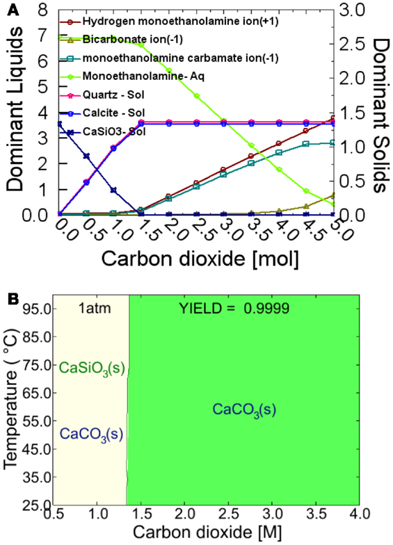
Figure 1. Thermodynamic simulation from OLI software. (A) Dominant liquid species and dominant solids as function of CO2 concentration at 60°C in 7.00M MEA – 1.31M CaSiO3 – 0.02M Calcite – 0.05M Quartz system; and (B) Equilibrium phase diagram between 25 and 100°C and at one atmosphere pressure in 7.00M MEA – 1.31M CaSiO3 – 0.02M Calcite – 0.05M Quartz system. Phase stability and yield diagrams for the carbonation of CaSiO3 in the system of 7.00M MEA – 1.31M CaSiO3 – 0.02M Calcite – 0.05M Quartz.
To validate the thermodynamic computation, the CaSiO3 powder was initially reacted in the MEA-CO2 solution via the “solution replacement” process. Figure 2 shows the XRD patterns of the reacted powder samples. For comparison, XRD profiles of the original CaSiO3 powder (wollastonite) and the product formed via the 12-day “single process” (12-day#) are also included in Figure 2. During the “solution replacement” process, the aragonite phase is detected as the main CaCO3 product after one day and becomes more evident over time. For the 12-day “single process” reaction, the aragonite phase is also detected but the intensity is lower. In addition, there are no calcite and crystalline silica phases observed in Figure 2. This differs from the results generated by the simulated thermodynamic computation in Figure 1, where the calcite and the quartz phases are dominant products under our reaction conditions. The formation of calcite or aragonite depends on the solution chemistry. Similar to the magnesium (Mg2+) in the sea water, MEA adsorption may be responsible for suppressing calcite formation. MEA carbamate ions (CH3CH2OHNHCOO−) may also suppress the calcite growth. Thus, mineral carbonation in the amine solution may be thermodynamically favorable but somewhat kinetically inhibited. Table 1 lists the degree of carbonation calculated from TGA and calcimetry. During the “solution replacement” process, the carbonate conversion increases gradually with the reaction time until it is up to ~27 wt% after 9 days, in agreement with the XRD trends in Figure 2, and thereafter it reaches a plateau. In the 12-day “single process” reaction, the carbonation conversion is lower, ~18 wt%. This is probably because the 12-day “single process” reaction continues to consume CO2 without further supplementation, resulting in a decrease of CO2 concentration in the MEA solution. In contrast in the 12-day “solution replacement” process, CO2 is continuously supplemented during the reaction time, thus, the CO2 concentration in the solution remains close to the saturation throughout the process. Therefore, it can be concluded that the CO2 concentration in the MEA aqueous solution is one of key factors affecting the carbonation reaction. As the aim of this paper is to evaluate the rHLPD-CS concept and its use to produce monolithic solids with a maximum CO2 sequestration, the “solution replacement” process will be the focus.
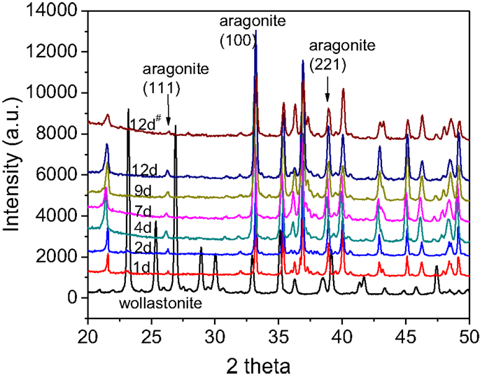
Figure 2. X-ray diffraction spectra of the reacted CaSiO3 powder at varying time via the “solution replacement” process, 12-day of “single process” (12-day#), and the original CaSiO3 powder.
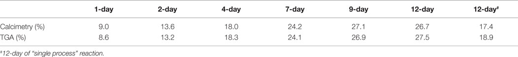
Table 1. Degree of carbonation of CaSiO3 powder calculated from calcimetry and TGA results.
When infiltrating the powder compact with the amine solution, the compact sample will absorb the MEA solvent in the pores due to its porous matrix. To determine the loss of MEA absorbed by the compact and the carbonation extent, thermal analysis was performed. Figure 3 shows the TGA/DSC plot of the reacted compact. The thermal analysis of pristine CaSiO3 powder is shown in the inset for comparison. The DSC curve for the reacted compact shows that there are two exothermic and two endothermic peaks. The first broad endothermic peak between 100 and 250°C with a maximum at ~162.3°C is due to the removal of physically adsorbed water. Its corresponding weight loss is 0.63 wt%. The first exothermic peak between 250 and 400°C centered at 316.5°C is from the combustion of residual MEA in the compact. The second endothermic peak at ~720.1°C is due to the decomposition of the CaCO3 in the product. The concomitant weight loss during this event is ~6.1 wt%. In the insert plot, a small endothermic peak along with 0.5 wt% of weight loss is observed between 500 and 800°C. This weight loss is derived from the decomposition of calcite impurity (1.1 wt% CaCO3 corresponds to 0.5 wt% CO2 decomposition) in CaSiO3 powder, thus the net weight loss from the carbonated sample is 5.6 wt%. Finally, a small exothermal peak between 825 and 875°C centering at ~833.5°C is observed without a weight loss. XRD of samples heated to 835°C shows they only contain crystalline wollastonite, indicating that a phase transition takes place during the decomposition of carbonated samples at elevated temperature.
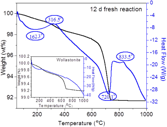
Figure 3. TGA/DSC curves for the 12-day “solution replacement” reaction and the original CaSiO3 powder (insert plot).
The first exothermic peak between 250 and 400°C is due to the combustion of 0.8 wt% residual MEA in the powder compact. This weight loss corresponds to ~0.30% of the 90 g of MEA-CO2 mother liquor. The surface area of CaSiO3 used in this work is 1.8 m2/g. If the surface area of the reacted compacts is ~2.0 m2/g due to the formation of CaCO3 nanoparticles, then ~40 MEA molecules/nm2 are absorbed on the surface, which is typical of a multilayer adsorption isotherm. According to the Union of Concerned Scientists (Freese et al., 2008), a typical 500-MW coal plant generates ~3.7 million metric tons of CO2 annually. If we assume the power plant operates 365 days/year and the MEA-CCS process is also operating 365 days/year, then the amount of CO2 emitted from the 500 MW coal fire power plant is assumed to be ~10 kton/day. If 10% of the emitted CO2 is sequestered by rHLPD and its process cycle is 1 day with an 80% carbonation conversion, then the amount of wollastonite, will be ~3.3 kton/day and the final product formed will be ~4.3 kton/day. TGA data show that the percentage of MEA absorbed on the final product is 0.8 wt%. Thus, ~34.7 metric ton of MEA will be absorbed on the surface of ~4.3 kton of the carbonated product. In our experiment, 9.3 g wollastonite is submerged in 90.0 g MEA-CO2 solution. We assume the density of the wollastonite compacts is 2.0 ton/m3 (2.0 g/cc) and the MEA-CO2 solution is 1.0 ton/m3 (1.0 g/cc), then the volume ratio of solid and solution is 1:19.4. To submerge ~3.3 kton (equals to 1650 m3) of wollastonite, the required volume of the MEA-CO2 solution is ~32,010 m3. This corresponds to ~32.0 kton of MEA-CO2 solution. As the MEA concentration in MEA solution is 30 wt% and CO2 concentration in 30 wt% MEA solution is 6.5%, the amount of pure MEA in a ~32.0 kton MEA-CO2 solution is calculated to be ~9.0 kton. Therefore, the loss of MEA due to the adsorption on the surface compacts will be 0.39 wt%/day, i.e., ~2.73 wt%/week. Thermal degradation of MEA solvent at 135°C is reported to be 2.5–6% per week (Davisa and Rochelle, 2009). This loss is similar to the MEA removed by physical adsorption during rHLPD.
Figure 4 shows the carbonation kinetics of CaSiO3 compacts calculated from XRD, TGA/DSC, and calcimetry data. For comparison, the reaction kinetics of CaSiO3 in powder form is also plotted. As expected, the carbonation conversion increases with reaction time, irrespective of the powder or compact phase, and the powder compact shows a slower reaction rate with a lower carbonation yield than the powder due to its structure. The porosity, bulk density, and dimension change before and after the rHLPD-CS process are summarized in Table 2. A decrease in porosity from 33.0 to 25.7%, an increase in density from 1.96 to 2.1 g/cm3, and the negligible shrinkage indicate that the compacts were densified after rHLPD-CS treatment. Figure 5 shows the SEM images of the green body and the reacted compact. Before the reaction, the pores are evident throughout the matrix and the particles are weakly packed (Figure 5A). After the reaction, the pores between CaSiO3 grains are filled by silica rich regions (red) and carbonate particles (green) (Figures 5B,C). The formation of densified microstructure confirms the results in Table 2.
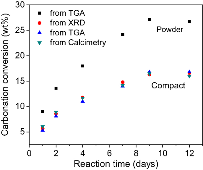
Figure 4. Degree of carbonation of CaSiO3 powder and compact as a function of reaction time calculated from different characterization methods.
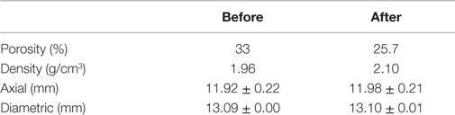
Table 2. Density, porosity, and dimensions before and after 12-day “solution replacement” reaction via rHLPD process.
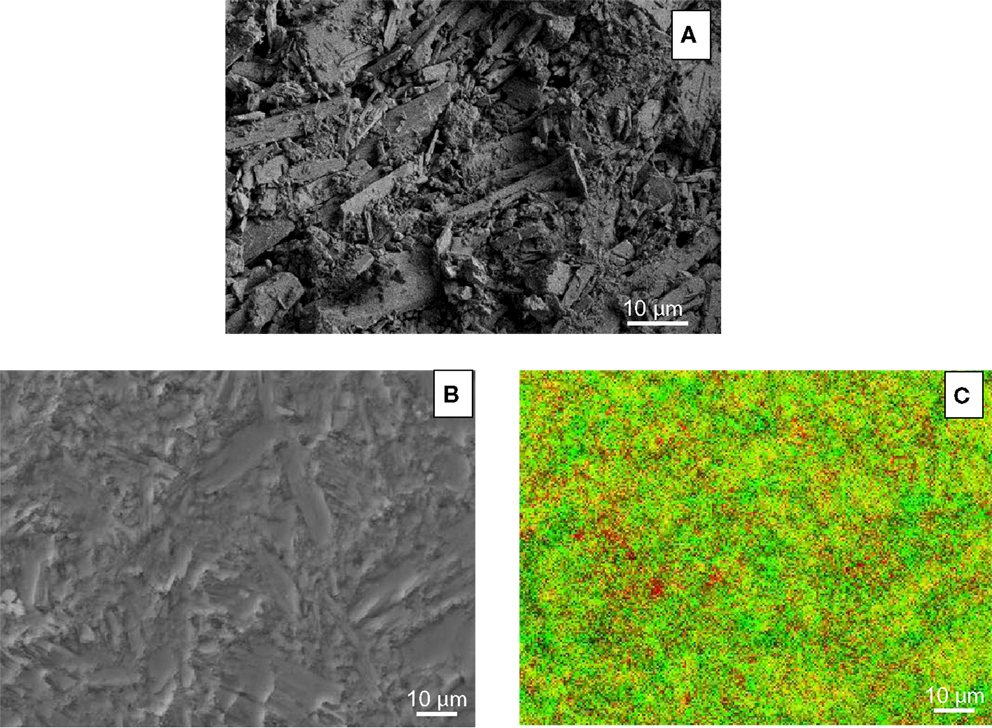
Figure 5. FESEM SE images of (A) fractured surface of CaSiO3 green body, (B) polished surface of 12-day of “solution replacement” compact, and (C) EDS chemical mapping of sample (B). In (C), yellow, red, and green represent CaSiO3, silica, and CaCO3, respectively.
Table 3 shows compressive strength of the reacted CaSiO3 compacts as a function of reaction time. The minimum compressive strength required for a monolithic material to be qualified as a dimension stone is also listed in Table 3. As the reaction progresses, the compressive strength gradually increases from 40.8 ± 3.7 MPa after 1-d reaction to 121.4 ± 8.7 MPa after 9-d reaction, thereafter no further change was observed. The compressive strength of the compact after 2-d of reaction is higher than that of the minimum requirement for commercial dimensional stones (ASTM C 503, 2008; ASTM C 568, 2008). Therefore, the reacted solids can be used as construction materials. However, the study of the relationship of the mechanical properties and the sample size is recommended to determine feasibility for commercial applications.
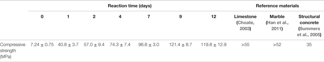
Table 3. Compressive strength of CaSiO3 compacts during “solution replacement” reaction.
Life Cycle Assessment of MEA Solution
The thermal degradation of the MEA solvent from a high temperature is minimized by using a low temperature process. However, the introduction of the CaSiO3 into the MEA solution may contaminate or degrade the solvent, reducing MEA capacity to absorb CO2. To investigate the reactivity of MEA solution in rHLPD-CS process, a 12-day of “CO2 replenishment” process was under taken. The original MEA-CO2 solution was not changed during the 12 days of reaction time, but the CO2 was supplemented at regular intervals and results were compared with the 12-day of “solution replacement” process. As shown in Table 4, the similar degree of carbonation, the porosity, and the compressive strength obtained from these two different processes suggests that the addition of CaSiO3 mineral in the MEA-CO2 solution has no influence on the reactivity of MEA on CO2 absorption during 12-day of “CO2 replenishment” process. Figure 6 shows the FTIR spectra of MEA-CO2 solution before and after 12-day of “CO2 replenishment” reaction. The spectrum of 30 wt% MEA solution is also shown as a reference. After adding CO2 into the 30 wt% MEA solutions, new peaks formed in the region of 1300–1600 cm−1. The peaks at 1491, 1564 cm−1 are attributable to 2-hydroxyethylcarbamate vibrations and the peaks at 1322, 1385, and 1464 cm−1 correspond to the carbamate formation, which are consistent with the IR peak assignments for CO2-loaded MEA solution reported in the literature (Jackson et al., 2009). The same IR spectrum is observed from the 12-day of “CO2-replenishment” solution. This further verifies that the MEA solution has not been degraded or contaminated at 60°C for 12-day. However, as mentioned above, the loss of MEA due to the physical adsorption in HLPS-CS process is similar to the amount of thermal degradation from the conventional MEA-CCS process.
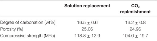
Table 4. Comparison of the 12-day “solution replacement” and the 12-day “CO2 replenishment” reactions.
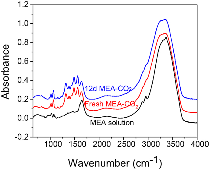
Figure 6. FTIR spectra of 30 wt% MEA aqueous solution, fresh MEA-CO2 solution and the residual MEA-CO2 solution after 12-day of “CO2 replenishment” reaction.
Hypothesized Mechanism and Perspective for rHLPD-CS Technology
Reactive hydrothermal liquid phase densification-carbon sequestration process in MEA-CO2 solution is illustrated in Figure 7. The dried porous CaSiO3 compact is first infiltrated with the MEA-CO2 solution and the individual pores in the compact are filled with the solution (Step 1). The proton dissociated from MEA-CO2 solution leaches Ca2+ from CaSiO3 particles (Step 2) and the free Ca2+ reacts with the bicarbonate to precipitate carbonate in the pores (Step 3). Meanwhile, the MEA molecule is released into the solution. As the reaction proceeds, the precipitated solids fill the pore spaces and the regenerated MEA continuously absorbs CO2 gases for further mineral carbonation (Step 4). The corresponding reaction process can be briefly written as follows:
Carbamate formation in MEA-CO2 solution:
Bicarbonate formation in MEA-CO2 solution:
Dissolution of CaSiO3 by proton when CaSiO3 is in MEA-CO2 solution:
Precipitation of CaCO3:
Thus, total reaction can be described as:
where, MEA is regenerated after CaSiO3 carbonation.
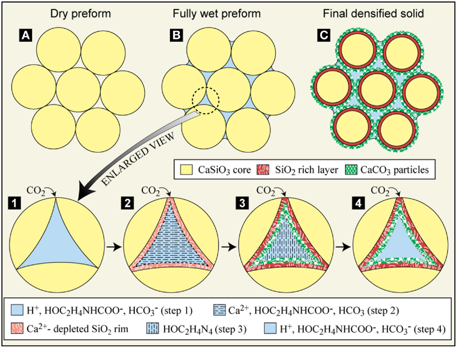
Figure 7. Schematics of rHLPD process [carbonation of CaSiO3 in CO2 saturated monoethanolamine (MEA) solution]. (A) dried porous preform (compact); (B) fully wet preform (compact) in CO2 saturated MEA solution; (C) densified solid in MEA-CO2 solution. Steps 1–4 show how the carbonation process occurs in the individual pores: Step 1 – CO2-saturated MEA solution in the pore; Step 2 – Ca2+ is leached by proton; Step 3 – precipitation of solids (CaCO3 and amorphous silica in this paper) and regeneration of MEA solution; Step 4 – CO2 saturated MEA solution in the pore.
As shown in Table 4, the use of rHLPD-CS technology produces monolithic solids with good mechanical properties, which have the potential to be used as cement or concrete construction materials. It is well known that cement manufacture is an energy-intensive process with a large amount of CO2 emission (~1 ton of CO2 emission/ton of cement manufacturing) due to the use of high temperature kilns (Natesan et al., 2003). Our preliminary results show that when we substituted gas-assisted reactive hydrothermal densification (g-rHLPD) processing for cement kiln firing, the energy consumption, and CO2 emission were significantly reduced (Gupta et al., in review). For example, if g-rHLPD products based on pure wollastonite with a 45 wt% carbonation conversion are used as a replacement for ~89 million metric tons of cement produced annually in the United States (Choate, 2003) the resulting ceramic product produced will use ~93.3% less energy (8.23 × 10⁹ kWh) than hydrated cement (122.13 × 10⁹ kWh) and a negative carbon footprint by ~11.7 wt% will be achieved (93 million metric tons of CO2 from Portland cement versus −10.84 million metric tons of CO2 from g-rHLPD cement) (Gupta et al., in review). However, this calculation does not account for the energy consumed in the formation of CO2. If the CO2 is derived from an energy-intensive amine process, the total energy consumed for g-rHLPD cement will be greatly increased. To produce 89 million metric tons of cement replacement, 13 million metric tons of CO2 are required to react with 76 million metric tons of wollastonite if the degree of wollastonite carbonation is 45 wt%. The specific energy consumption of the amine process is ~4300 kJ/kg CO2 capture (Han et al., 2011). Therefore, the total energy consumed in the sequestration of 13 million metric tons of CO2 will be 15.53 × 10⁹ kWh, almost two times higher than the energy consumed in manufacturing 89 million metric tons of g-rHLPD cement, 8.23 × 10⁹ kWh. However, this is justified because rHLPD-CS technology directly sequesters CO2 at a low temperature than required to strip MEA from CO2. In addition, the compression and burial steps are also eliminated.
The ideal CO2 sequestration rate for mineral carbonation in the rHLPD-CS process should be the same as the rate of CO2 absorption by the MEA solution, i.e., equal to the rate of CO2 emission from the plant. However, experimental results show the CaSiO3 (~9 μm) carbonation reaction in MEA-CO2 solution at 60°C is a rather slow process. Only ~27 wt% of carbonate conversion is obtained after 9 days of reaction. If the temperature is higher than 60°C, a fast reaction rate can be achieved, but the thermal degradation of the solvent is increased accordingly. It is well known that decreasing the particle size of the mineral result in accelerating the reaction rate (Summers et al., 2005), but it increases energy and/or economic costs, which must be considered relative to the energetics of MEA-CO2 stripping. A feasible and practical approach is to incorporate rHLPD-CS technology with the existing MEA process configurations but without interrupting the main MEA-based CCS process. Figure 8 depicts the modified process configurations. In the absorber, the aqueous MEA-CO2 solution is divided into two lines, line 1 and line 2. A majority of the solution is led via line 1 to the stripper and a small portion of the solution is introduced via line 2 into the rHLPD-CS reactor, where the CO2 in the MEA-CO2 solution is sequestered by the mineral carbonation and thereafter the solution is led via line 3 into the stripper. To accelerate the carbonation reaction, the CO2 concentration in the rHLPD-CS reactor must remain at a high level which is accomplished by continuously flowing the MEA-CO2 solution from the absorber through the reactor to the stripper. Since the rHLPD-CS reactor is “isolated” from the main amine-scrubbing process, the reaction rate and time in the rHLPD-CS reactor will not affect the CCS process. After a certain time, the solidified materials can be removed from the rHLPD-CS reactor for future application. In the future if an ideal material, which can sequester CO2 as quickly as the CO2 absorption, can be economically manufactured, only the absorber and the rHLPD-CS reactor would be required for use in the CCS process and the stripper could be removed. As the main goal of this paper is to propose a concept by which monolithic materials can be formed in the MEA-CO2 solution via rHLPD-CS process at a low temperature, many reaction factors, such as the type of natural minerals and/or waste solids (such as fly ash and slag), the particle size of minerals/waste solids, the porosity of the compact, the size of compact, and the CO2 concentration, are not optimized. We believe that these studies will help us to get a better road-map to achieve carbonate monolithic materials with maximized economic merit in the amine-scrubbing process.
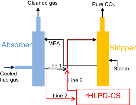
Figure 8. Incorporation of rHLPD to current MEA-based CCS technology. Black lines represent current process, and red lines represent modifications utilizing rHLPD technology.
Conclusion
Reactive hydrothermal liquid phase densification-carbon sequestration technology, a method to solidify (densify) monolithic materials in the amine-based CCS solution by mineral carbonation show potential for reducing the energy required to capture and sequester CO2. The CO2 sequestration by mineral carbonation at a low temperature of 60°C considerably reduces the energy consumed on the regeneration of amine at a high temperature, and the formation of a carbonate product permanently sequesters CO2, thus eliminating the need to compress and store CO2. The negligible shrinkage, the reduced porosity, the densified microstructure, and high compressive strength of ~121 MPa obtained via rHLPD-CS indicate that the samples not only are solidified but also have potential use as construction and infrastructure materials. In addition, the use of low temperature processing prolongs the life cycle of amine solution by reducing the thermal degradation of CO2 that occurs at high operating temperatures. However, the slow rate of CaSiO3 carbonation by MEA-CO2 solution renders this process unsuitable as a self-standing CCS process. Any future process incorporating HLPD technology will need to be integrated with the MEA-based CCS process.
Author Contributions
The concept was invented by RR. QL designed the experiments and executed the idea of RR. SG did the mechanical properties and microstructure analysis. LT, SQ, and QL did a most of the experiments. VA and RR are inventors of rHLPS and advised on the experiments.
Conflict of Interest Statement
Richard E. Riman is founder and an equity holder of Solidia Technologies, Inc. The remaining co-authors declare that the research was conducted in the absence of any commercial or financial relationships that could be construed as a potential conflict of interest.
Acknowledgments
The authors wish to acknowledge the generous support by Solidia Technologies, Inc. for this research and Ms. Janet Pescinski of Rutgers University for her editorial comments.
References
ASTM C 503. (2008). Standard Specification for Marble Dimension Stone. Philadelphia, PA: American Society for Testing and Materials, 19095.
ASTM C 568. (2008). Standard Specification for Limestone Dimension Stone. Philadelphia, PA: American Society for Testing and Materials, 19095.
Banerjee, R., Phan, A., Wang, B., Knobler, C., Furukawa, H., O’Keeffe, M., et al. (2008). High-throughput synthesis of zeolitic imidazolate framworks and application to CO2 capture. Science 319, 939–943. doi: 10.1126/science.1152516
Bara, J. E., Camper, D. E., Gin, D. L., and Noble, R. D. (2010). Room-temperature ionic liquids and composite materials: platform technologies for CO2 capture. Acc. Chem. Res. 43, 152–159. doi:10.1021/ar9001747
Brennecke, J. R., and Gurkan, B. E. (2010). Ionic liquids for CO2 capture and emission reduction. J. Phys. Chem. Lett. 1, 3459–3464. doi:10.1021/jz1014828
Choate, W. T. (2003). Energy and Emission Reduction Opportunities for the Cement Industry. Available at: http://www1.eere.energy.gov/manufacturing/industries_technologies/imf/pdfs/eeroci_dec03a.pdf
CRC. (1990–1991). “Chapters 6 and 8,” in Handbook of Chemistry and Physics, 71st, ed. Lide D. R. Boston: CRC Press.
Davisa, J., and Rochelle, G. (2009). Thermal degradation of monoethanolamine at stripper conditions. Energy Procedia 1, 327–333. doi:10.1016/j.egypro.2009.01.045
Eisaman, M. D., Alvarado, L., Larner, D., Wang, P., Garg, B., and Littau, K. A. (2010). CO2 separation using bipolar membrane electrodialysis. Energy Environ. Sci. 4, 1319–1328. doi:10.1039/C0EE00303D
Folger, P. (2010). Carbon Capture: A Technology Assessment, CRS Report for Congress, R41325. Available at: http://www.cmu.edu/epp/iecm/rubin/
Freese, B., Clemmer, S., and Nogee, A. (2008). Coal Power in a Warming World, a Sensible Transition to Cleaner Energy Options. Union of Concerned Scientists. Available at: http://www.ucsusa.org/assets/documents/clean_energy/Coal-power-in-a-warming-world.pdf
Haders, D., Burukhin, A., Zlotnikov, E., and Riman, R. E. (2008). TEP/EDTA doubly regulated hydrothermal crystallization of hydroxyapatite films on metal substrates. Chem. Mater. 20, 7177–7187. doi:10.1021/cm071628c
Han, C., Grave, K., Neathery, J., and Liu, K. (2011). Simulation of the energy consumption of CO2 capture by aqueous monoethanolamine in pilot plant. Energy Environ. Res. 1, 67–68. doi:10.5539/eer.v1n1p67
Huijgen, W. J., Witkamp, G. J., and Comans, R. N. J. (2006). Mechanisms of aqueous wollastonite carbonation as a possible CO2 sequestration process. Chem. Eng. Sci. 61, 4242–4251. doi:10.1016/j.ces.2006.01.048
Jackson, P., Robinson, K., Puxty, G., and Attalla, M. (2009). In situ Fourier transform-infrared (FT-IR) analysis of carbon dioxide absorption and desorption in amine solutions. Energy Procedia 1, 985–994. doi:10.1016/j.egypro.2009.01.131
Lackner, K. S., Wendt, C. H., Butt, D. P., Joyce, E. L., and Sharp, D. H. Jr. (1995). Carbon dioxide disposal in carbonate minerals. Energy 20, 1153–1170. doi:10.1016/0360-5442(95)00071-N
Lackner, K. S., and Ziock, H. J. (2000). Integration of CO2 capture and mineral carbonation by using recyclable ammonium salts. Mod. Power Syst. 20, 31–32.
Lee, S. C., Choi, B. Y., Lee, T. J., Ryu, C. K., Ahn, Y. S., and Kim, J. C. (2006). CO2 absorption and regeneration of alkali metal-based solid sorbents. Catal. Today 111, 385–390. doi:10.1016/j.cattod.2005.10.051
Lencka, M. M., and Riman, R. E. (1993). Thermodynamic modeling of hydrothermal synthesis of ceramic powders. Chem. Mater. 5, 61–70. doi:10.1021/cm00025a014
Li, X., Remias, J. E., Neathery, J. K., and Liu, K. (2011). NF/RO faujasite zeolite membrane-ammonia absorption solvent hybrid system for potential post-combustion CO2 capture application. J. Memb. Sci. 366, 220–228. doi:10.1016/j.memsci.2010.10.007
MacKenzie, A., Granatstein, D. L., Anthony, E. J., and Abanades, J. C. (2007). Economics of CO2 capture using the calcium cycle with a pressurized fluidized bed combustor. Energy Fuels 21, 920–926. doi:10.1021/ef0603378
Matter, J. M., and Kelemen, P. B. (2009). Permanent storage of carbon dioxide in geological reservoirs by mineral carbonation. Nat. Geosci. 2, 837–841. doi:10.1038/ngeo683
Metz, B., Davidson, O., de Conick, H. C., Loos, M., and Meyer, L. A. (2005a). IPCC Special Report on Carbon Dioxide Capture and Storage. New York: Cambridge University Press, 197–265.
Metz, B., Davidson, O., de Coninck, H., Loos, M., and Meyer, L. (eds) (2005b). IPCC Special Report on Carbon Dioxide Capture and Storage. Prepared by Working Group III of the Intergovernmental Panel on Climate Change. New York: Cambridge University Press.
Natesan, M., Smith, S., Humphreys, K., and Kaya, Y. (2003). “The cement industry and global climate change: current and potential future cement industry CO2 emissions,” in Greenhouse Gas Control Technologies – 6th International Conference (Pergamon: Oxford), 995–1000.
Pachauri, R. K., Reisinger, A., and Core Writing Team. (2007). IPCC, Climate Change 2007: Synthesis Report. Contribution of Working Groups I. II and III to the Fourth Assessment Report of the Intergovernmental Panel on Climate Change. Geneva: IPCC, 104.
Rao, A. B., and Rubin, E. S. (2000). A technical, economic, and environmental assessment of amine-based CO2 capture technology for power plant greenhouse gas control. Environ. Sci. Technol. 36, 4467–4475. doi:10.1021/es0158861
Rao, A. B., and Rubin, E. S. (2002). A technical, economic, and environmental assessment of amine -based CO2 capture technology for power plant greenhouse gas control. Environ. Sci. Technol. 36, 4467–4475. doi:10.1021/es0158861
Riman, R. E., and Atakan, V. (2012a). Systems and Methods for Carbon Capture and Sequestration and Composition Derived Therefrom. U.S. Patent No. 8114367 B2, Washington, DC: U.S. Patent and Trademark Office.
Riman, R. E., and Atakan, V. (2012b). Method of Hydrothermal Liquid Phase Sintering of Ceramic Materials and Products Derived Therefrom. U.S. Patent No. 8,313,802 B2, Washington, DC: U.S. Patent and Trademark Office.
Rochelle, G. T. (2009). Amine scrubbing for CO2 capture. Science 325, 1652–1654. doi:10.1126/science.1176731
Summers, C. A., Dahlin, D. C., Rush, G. E., O’Connor, W. K., and Gerdemann, S. J. (2005). Grinding methods to enhance the reactivity of olivine. Min. Metall. Process. 22, 140–144.
Keywords: carbon sequestration, ceramics, calcium carbonate, calcium silicate, densification, carbon utilization, valorization
Citation: Li Q, Gupta S, Tang L, Quinn S, Atakan V and Riman RE (2016) A Novel Strategy for Carbon Capture and Sequestration by rHLPD Processing. Front. Energy Res. 3:53. doi: 10.3389/fenrg.2015.00053
Received: 16 September 2015; Accepted: 03 December 2015;
Published: 22 January 2016
Edited by:
Ah-Hyung Alissa Park, Columbia University, USAReviewed by:
Youngjune Park, Gwangju Institute of Science and Technology, South KoreaMai Uibu, Tallinn University of Technology, Estonia
Copyright: © 2016 Li, Gupta, Tang, Quinn, Atakan and Riman. This is an open-access article distributed under the terms of the Creative Commons Attribution License (CC BY). The use, distribution or reproduction in other forums is permitted, provided the original author(s) or licensor are credited and that the original publication in this journal is cited, in accordance with accepted academic practice. No use, distribution or reproduction is permitted which does not comply with these terms.
Greeshma Gadikota contributed to the editorial process of this article.
*Correspondence: Richard E. Riman, riman@rci.rutgers.edu