The Electrochemical Characteristics and Applicability of an Amorphous Sulfide-Based Solid Ion Conductor for the Next-Generation Solid-State Lithium Secondary Batteries
 Yuichi Aihara1*
 Seitaro Ito1
 Ryo Omoda1
 Takanobu Yamada1
 Satoshi Fujiki1
 Taku Watanabe1
 Youngsin Park2
Seokgwang Doo2
Youngsin Park2
Seokgwang Doo2
- 1Samsung R&D Institute Japan, Minoo-shi, Japan
- 2Samsung Advanced Institute of Technology, Samsung Electronics Co., Ltd, Suwon-si, South Korea
Sulfide-based solid electrolytes (SEs) are of considerable practical interest for all solid-state batteries due to their high ionic conductivity and pliability at room temperature. In particular, iodine containing lithium thiophosphate is known to exhibit high ionic conductivity, but its applicability in solid-state battery remains to be examined. To demonstrate the possibility of the iodine-doped SE, LiI–Li3PS4, was used to construct two different types of test cells: Li/SE/S and Li/SE/LiNi0.80Co0.15Al0.05 cells. The SE, LiI–Li3PS4, showed a high ionic conductivity approximately 1.2 mS cm−1 at 25°C. Within 100 cycles, the capacity retention was better in the Li/SE/S cell, and no redox shuttle was observed due to physical blockage of SE layer. The capacity fade after 100 cycles in Li/SE/S cell was approximately 4% from the maximum capacity observed at 10th cycle. In contrast, the capacity fade was much larger in Li/SE/LiNi0.80Co0.15Al0.05 cell, probably due to the decomposition of the electrolyte at the operating potential range. Nevertheless, both the Li/SE/LiNi0.80Co0.15Al0.05 and Li/SE/S cells exhibited high coulombic efficiencies above 99.6 and 99.9% during charge–discharge cycle test, respectively. This indicates that a high energy density can be achieved without an excess lithium metal anode. In addition, it was particularly interesting that the SE showed a reversible capacity about 260 mAh (the value calculated using the net solid electrolyte weight). This electrolyte may behave not only as an ionic conductor but also as a catholyte.
Introduction
Nowadays, requirements for batteries have been increasingly stringent in terms of energy density and safety because of the diversity of functions of electronic devices and their usage as a power source especially in transportation. Lithium ion batteries (LIBs) have been in the market over two decades because of their high energy density, but even better batteries have been sought to meet ever stricter requirements (Scrosati and Garche, 2010). Solid-state lithium batteries have received considerable attention since the inception of primary and secondary lithium batteries (Weppner, 1981). From viewpoints of (1) theoretical capability and (2) physical properties, solid-state lithium batteries have been believed to be next-generation power sources. Unfortunately, the commercial applications of all solid-state batteries are limited to a few cases, such as the Li–I primary battery, and thin film type solid-state batteries because of serious technical challenges (Bates et al., 1993).
Recently, fast lithium ion conductors have been found in sulfide compounds (Kamaya et al., 2011). A large difference between typical oxide- and sulfide-based solid electrolytes (SEs) is in their physicomechanical properties, especially on their deformability. In particular, a large grain boundary resistance, observed in oxide SEs, does not unambiguously exist in many sulfide SEs because of the pliable nature of the sulfide compounds; seamless reaction interfaces can be easily formed by a cold press without high temperature sintering (Tatsumisago et al., 2002). Recently, excellent cell characteristics have been reported using a small pellet cell (Ogawa et al., 2012). Unfortunately, most of these studies adopted a Li–In alloy, because of its stable cycle due to the solid solution, unlike a dissolution–deposition reaction. As well as a conventional LIB, a rocking chair type all-solid-state battery (Ogawa et al., 2012) and Li–S battery (Nagata and Chikusa, 2014) have also been proposed. We have shown the possibility of a practical 2-Ah class all-solid LIB using a sulfide electrolyte (Ito et al., 2014). We also have investigated the anode kinetics using Li3PS4, i.e., Li2S:P2S5 = 75:25 (Yamada et al., 2015). Use of the solid-state electrolyte greatly facilitates the design of a highly save battery unlike the ones using flammable organic liquid solvents.
Among many sulfide compounds, lithium thiophosphates containing halogens exhibit relatively high ionic conductivities. Mercier et al. (1981) reported a structure and property relation of Li2S–P2S5–LiI systems. They reported that the addition of LiI to Li2S–P2S5 lowered the glass transition temperature, and the material had a high ionic conductivity of approximately 10−3 S cm−1 at 25°C when the molar ratio of LiI:0.66Li2S–0.33P2S5 is 0.45. Ohtomo et al. (2013) investigated the electrochemical stability and ionic conductivity of LiI–Li2O–Li2S–P2S5 glass. They found that 30LiI–70 (0.07Li2O–0.68Li2S–0.25P2S5) is stable over 0–10 V and exhibited a high ionic conductivity of 1.3 × 10⁻³ S cm−1. The stability and ionic conductivity of Li7P2S8I was reported by Rangasamy et al. (2015). They observed that the addition of iodine to the β-Li3PS4-based structure resulted in good electrochemical stability against an Li metal anode while maintaining a conductivity of 6.3 × 10⁻⁴ S cm−1 at room temperature. These literatures indicate that iodine-containing lithium thiophosphates have great potential and that there is considerable practical interest in investigating the applicability of this class of materials as SE in all solid-state batteries.
In this paper, we report the cell cycle characteristics longer than 100 cycles with the theoretical sulfur redox capacity plus the electrolyte redox capacity, using an amorphous LiI–Li3PS4 electrolyte, referring with LiNi0.80Co0.15Al0.05 (NCA) cathode. To clarify the origin of the excess cell capacity from a net sulfur specific capacity, the electrolyte was also tested as a cathode. It was found that amorphous LiI–Li3PS4 had a reversible capacity of about 260 mAh g−1 within the potential range of 1.3–2.7 V versus Li/Li+. The possibility of using a sulfide-based solid electrolyte in solid-state lithium secondary batteries using was also discussed.
Experimental
Materials
The solid-state electrolyte (SE), LiI–Li3PS4, was prepared by the mechanical milling method in an Ar-gas-filled vessel was used for above preparation to prevent degradation of the sample. Specifically, 35 mol% of LiI (Aldrich, 99.999%) and 65mol% of 0.75Li2S (Alfa, 99.9%)–0.25P2S5 (Aldrich, 99%) were mixed at 380 rpm for 35 h (70 cycles of 20 min of operation and 10 min of interval) by using Fritsch (Idar-Oberstein) P-5 grinding bowl fasteners. The synthesized electrolyte was characterized using Raman spectroscopy (JASCO, NRS-3100, Tokyo) and X-ray diffraction (XRD, CuKα, 45 kV, 40 mA, Panalytical, Empyrean XRD, Almelo).
LiNi0.80Co0.15Al0.05 (NCA) was coated with Li2O–ZrO2 (LZO) and was used for the reference cathode material. The preparation of LZO–NCA was given in our previous report (Ito et al., 2014). An NCA cathode composite was prepared by mixing the LZO–NCA, LiI–Li3PS4 and a vapor grown carbon fiber (VF, the fiber diameter: approximately 200–500 nm, the length: approximately 5–10 μm) in the weight ratio of 0.60:0.35:0.05 using a mortar (hand mixing) in an Argon box (MBraun, LABmaster dp, H2O < 0.1 ppm, O2 < 0.1 ppm).
For preparing the lithium-sulfur (Li–S) cell, the carbon-sulfur (C–S) composite was first prepared using the ball milling method. Dried sulfur powder (Alfa Aesar) was mixed with an activated carbon (MAXSORB® MSC-30, Kansai Coke and Chemicals Co., Ltd.) in the weight ratio of 26:74 wt% in an argon-filled 45-mL zirconia vessel by using high-energy ball milling at 370 rpm for 10 h (20 cycles of 20 min operation and 10 min interval). Then, the C–S composite was further mixed with LiI–Li3PS4 (SE) in the weight ratio 0.5:0.5 to make a carbon-sulfur-solid electrolyte (C–S–SE) composite, using the same high energy ball milling method. The mixing procedure is the same as for the C–S preparation. The weight fraction of the prepared sulfur cathode composite was 0.37:0.13:0.50 for sulfur:carbon:LiI–Li3PS4. The C–SE composite (0.21:0.79) was similarly prepared using the ball milling method. Lithium foil (t = 30 μm, Honjo Metal, Osaka) was used for the anode.
Differential scanning calorimetry (DSC) was performed on a SII X-DSC7000 calorimeter (Seiko SII, Tokyo) using an Ar-filled closed pan for the prepared LiI, Li3PS4, LiI–Li3PS4, C–S–SE, and C–SE composites. The measurements were performed between room temperature and 400°C with scanning rate of 2°min−1.
For the evaluation of the applicability of cathode materials, the in-house electrochemical cell (two electrodes cell, φ 13 mm) was adopted. The cell preparation method and the schematic structure are also described in our previous paper (Ito et al., 2014). The details of the prepared cells are listed in Table 1.
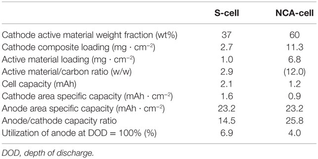
Table 1. Specification of the test cells.
Electrochemical Measurements
The ionic conductivity of the SE was determined from the cell constant and bulk resistance observed in electrochemical impedance spectroscopy (EIS). The EIS was performed using an AUTOLAB PGSTAT30 with an frequency response analysis FRA module (Metrohm Autolab, Utrecht) controlled by a personal computer. Linear sweep voltammetry (LSV) was performed using the same equipment. An asymmetric two electrodes cell with a Pt working electrode and a lithium counter (reference) electrode was prepared for LSV. The galvanostatic charge/discharge profiles were obtained using a battery test station, TOSCAT3100 (Toyo system, Iwaki) at 25°C position in a temperature chamber.
Results
Characterization of LiI–Li3PS4
The crystallinity and anion structure of the SE, LiI–Li3PS4, was characterized by Raman spectroscopy (Figure 1) and XRD (Figure 2). It is clear from the Raman spectra that the reaction proceeded because of the high-energy ball milling within the first 5 h. After 35 h of ball milling, the intensities of the P2S7 dimer diminished in the spectrum. However, even after 35 h, the P2S6 peak was not completely suppressed. Furthermore, some reaction residue of LiI was found in the XRD pattern. The XRD pattern and Raman spectrum did not show any obvious change after 35 h, and so synthesis was discontinued at this point. From the above results, the synthesized electrolyte was mostly amorphous containing a small fraction of P2S6 dimer and crystalline LiI. The main anion frame structure was (and I−).
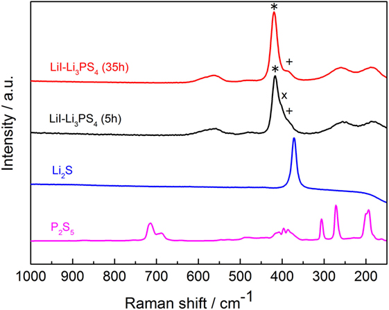
Figure 1. Raman spectra of the starting materials and the solid-state electrolyte, LiI–Li3PS4 after ball milling for 5 h (black) and 35 h (red). *420 cm−1: stretching of PS4 anion; x405 cm−1: stretching of P2S7 anion; +387 cm−1: stretching of P2S6 anion.
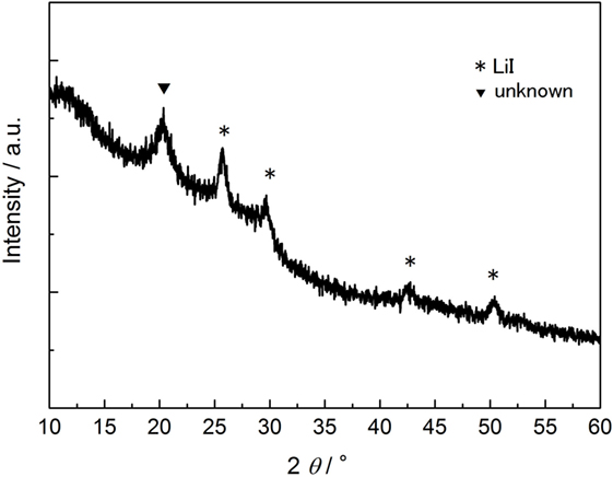
Figure 2. X-ray diffraction of LiI-Li3PS4. *Peaks assigned in the reaction residue of LiI crystalline. Li2S was completely consumed by the reaction.
The temperature dependence of the ionic conductivity for LiI–Li3PS4 is plotted in Figure 3. The temperature dependence was a typical Arrhenius type, and the activation energy of the ionic conductivity was 29.1 ± 1.1 kJ mol−1. The ionic conductivity was 1.2 mS cm−1 at 25°C, and it is approximately 10 times than that of amorphous Li3PS4 SE (Yamada et al., 2015).
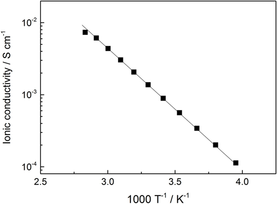
Figure 3. Arrhenius plot of the ionic conductivity of LiI–Li3PS4.
The electrochemical stability of the electrolyte was determined using LSV (Figure 4). The potential was scanned from the open circuit potential to 5.0 V versus co-counter/reference electrodes of Li/Li+. At 2.8 V, a small spike peak was observed for LiI–Li3PS4. This peak might originate from isolated lithium iodide and its anodic oxidation. Although the anodic decomposition current was not significant, the current profile indicated a small anodic oxidation above 3.1 V for LiI–Li3PS4. On the contrary, no anodic current was observed in Li3PS4 cell.
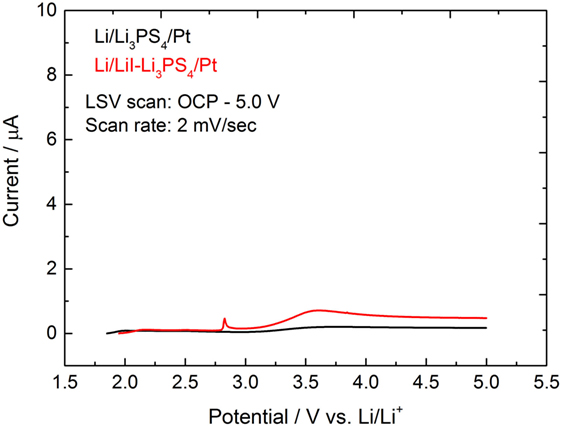
Figure 4. Linear sweep voltammogram of Li3PS4 and LiI–Li3PS4 at 25°C. WE: Pt, CE-RE: Li, scan rate: 2 mV s−1.
Li/LiI–Li3PS4/LZO–NCA Cell (NCA Cell)
The discharge profiles and capacity attenuation during 100 cycles for Li/LiI–Li3PS4/LZO–NCA cell (NCA cell) is shown in Figures 5A,B. The cell showed initial discharge capacities of approximately 134 and 94 mAh g−1 at 0.05 and 0.5°C, respectively. These cathode specific capacities were larger than in our previous study (Ito et al., 2014). However, the specific capacity decreased from 95 to 70 mAh g−1 after 100 cycles with the charge/discharge condition of 0.1 C CC–CV/0.5 C CC. The capacity fade was much faster than that in Graphite/Li2S–P2S5 (80:20 mol%)/LZO–NCA (Ito et al., 2014). The initial coulombic efficiency was 69.4% and gradually increased to 99.0% by the sixth cycle. The average coulombic efficiency during the last 50 cycles was 99.6%. After 100 cycles, the average cell closed potential decreased due to the increase of iR drop up in the first 2 s right after the galvanostatic charge/discharge started. These performance characteristics indicate that the cell-specific capacity gradually decreased due to the increase of cell resistance with the same cutoff potential.
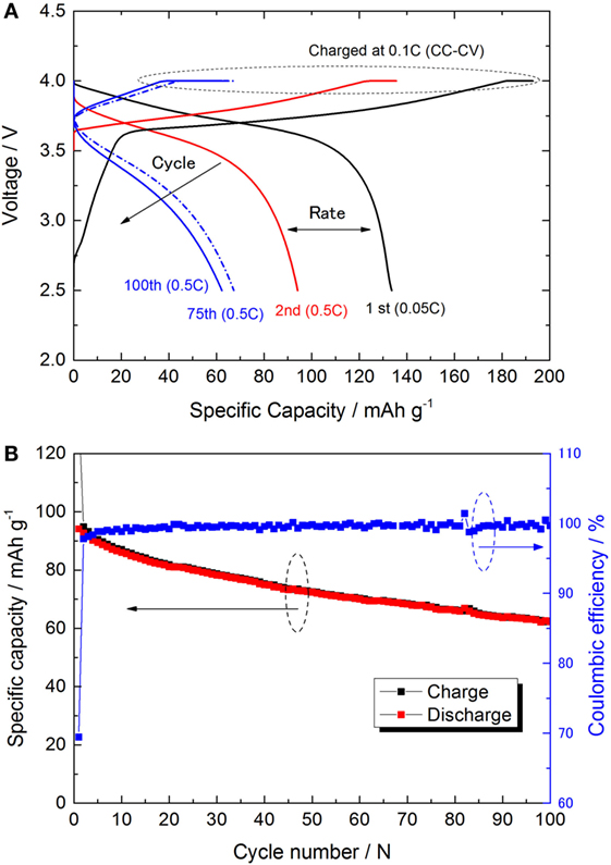
Figure 5. (A) Charge/discharge curves of NCA-cell for 1st, 10th, and 100th cycle at 25°C. The 0.1 C constant current–4.0 V constant voltage (CC–CV) mode was adopted for all the charge sequences. First discharge was done at 0.05 C to check the full capacity. (B) Charge/discharge capacities and the coulombic efficiency are plotted versus the cycle (within the 2nd cycle to 100th cycle).
Li/LiI–Li3PS4/C–S Cell (S Cell)
The discharge profiles and capacity attenuation during 100 cycles for the Li/LiI–Li3PS4/S (S cell) is shown in Figures 6A,B. On account of the expected poor rate capability of the S cell, the discharge rate was fixed at 0.15 C (0.25 mA cm−2) with the charge/discharge cut off potentials between 3.1 and 1.3 V (constant current charge/discharge). In Figure 6A, the discharge profiles including 1st, 10th, and 100th are shown at the same discharge rate. The initial cell capacity was only about 1300 mAh (the value calculated using the net sulfur weight), lower than what is expected for a Li–S cell of this type. The specific capacity increased with the cycle and achieved a maximum value of 1688 mAh (calculated using the net sulfur weight) at the 10th cycle.
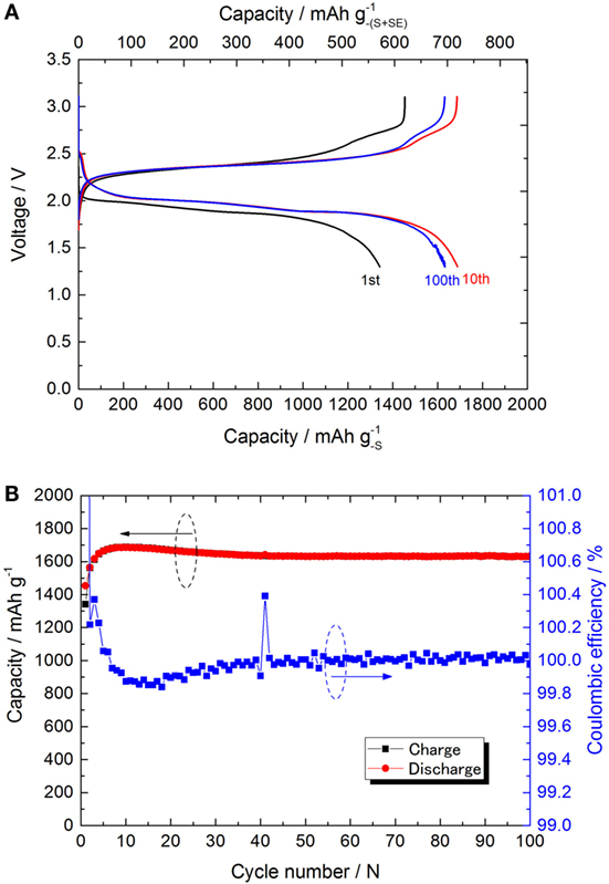
Figure 6. (A) Charge/discharge curves of S-cell for 1st, 10th, and 100th cycle at 25°C. All the charge/discharge was done at 0.15 C (0.25 mA cm−2) constant current with the cutoff potential of 3.1 and 1.3 V. (B) Charge/discharge capacities and the coulombic efficiency are plotted versus the cycle.
After the 10th cycle, the specific capacity gradually decreased to 1622 mAh by 100th cycle. The coulombic efficiency reached beyond 99.9% after the 30th cycle. From the maximum capacity obtained at the 10th cycle, the specific capacity decreased only 4% in the last 90 cycles. Also, it is clear that no redox shuttle was observed. This result is consistent with our previous report on the all-solid-state Li–S cell (Yamada et al., 2015). Unfortunately, the cycle performance was lower than the expectation. Nevertheless, in this paper, we changed the SE and the carbon support used in the cathode. Both the material change positively influenced the cell performance. The results are summarized and compared with the former NCA cell in Table 2.
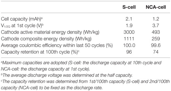
Table 2. Summary of the cell characteristics.
Li/LiI–Li3PS4/C–LiI–Li3PS4 (E Cell)
Because of the strange charge plateau above 2.5 V, the possibility of a reversible redox reaction of the electrolyte was investigated. Recently, the reversible reaction of Li3PS4 and “sulfur-rich lithium polysulfidophosphates” has been suggested (Lin et al., 2013; Hakari et al., 2015). Reactivity of the carbon–electrolyte (C–SE) composite was investigated using a similar cell configuration to the S-cell, but it did not contain sulfur in the cathode composite. The galvanostatic charge/discharge profile and the capacity attenuation are plotted in Figures 7A,B. The redox capacity calculated using the weight of the electrolyte in the cathode composite was 261 mAh at 10th cycle. The charge/discharge capacities were quite stable during the cycle (the coulombic efficiency was always nearly equal to 100%). Although the actual reaction scheme is unclear, two potential plateaus were clearly observed in the discharge profile.
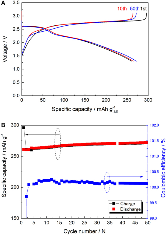
Figure 7. (A) Charge/discharge curves of E-cell for 1st, 10th, and 50th cycle at 25°C. All the charge/discharge was operated by the same condition of S-cell. (B) Charge/discharge capacities and the coulombic efficiency are plotted versus the cycle.
To examine the condition of the electrolyte in the C–SE composite, we measured Raman spectroscopy of our sample. However, after the ball milling, the Raman shift related to the electrolyte (420 cm−1, anion structure) was not observable. Other observed peaks were assigned to D/G bands of graphite (1570–1360 cm−1). DSC was performed (Figure 8) and the results are summarized in Table 3. There was a significant difference between the profiles of Li3PS4 and LiI–Li3PS4. LiI–Li3PS4 exhibited a large peak at 160.9°C. This exothermic peak might be related to the reorientation and crystallization of LiI. In the scan, the glass transition appeared just before the crystallization of LiI. The heat flow decreases slightly in the SE and C–SE samples. Furthermore, the other peaks related to Li3PS4 (crystallizing and transformation to the thio-LISICON phase) showed high temperature shifts. The peak pattern of the C–SE composite was unchanged after ball milling with activated carbon. However, the sharp peak shifted to high temperature in comparison with LiI–Li3PS4. The reason for this high temperature shift is obscure. In the C–S–SE sample, the peak pattern was completely changed by the ball milling. The sulfur (S8) generally does not show any exothermic peak, and only endothermic melting peaks were observed before 300°C. However, the C–S–SE composite showed only a small endothermic peak around 107°C and two exothermic peaks. The presence of excess sulfur certainly changes the chemical environment and must be promoting alternate chemical reactions. Unfortunately, it was still not clear whether the materials were changed by the heating during the DSC or by the mechanical milling.
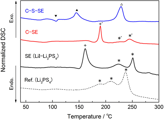
Figure 8. DSC chart for the electrolytes and composites at the first heating. The heat flow was normalized by the sample weight. DSC scan rate was 2°C min−1.
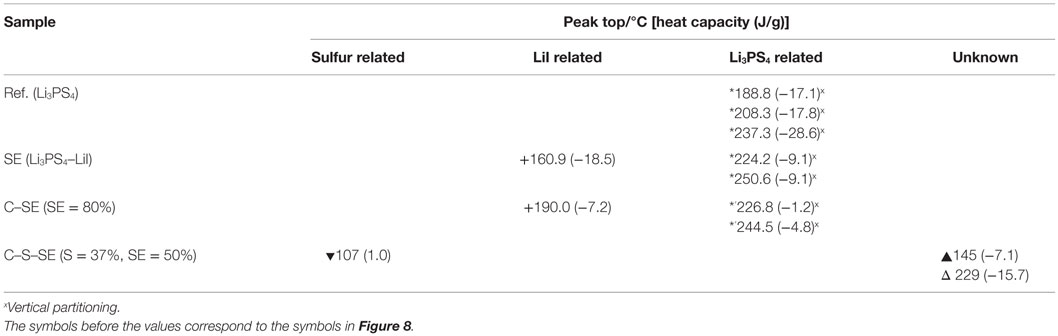
Table 3. Summary of the DSC analysis of the samples.
Discussion
Characteristic of LiI–Li3PS4
In this paper, we have demonstrated two types of lithium metal secondary cells using a solid-state electrolyte based on an amorphous LiI–Li3PS4. This electrolyte consists of 48 mol% ortho-Li3PS4, and the 52 mol% of LiI. Although LiI is an ionic conductive material (3.2 μS cm−1) (Rao et al., 1978), it is impossible to explain the improvement of ionic conductivity by the addition of LiI to Li3PS4, because of the poorer conductivity of LiI than that of Li3PS4. We assumed that the carrier number did not significantly change upon 52 mol% substitution by LiI compared to amorphous Li3PS4. The PS4 anion actually has a symmetrical tetrahedron structure, and substitution with LiI replaces this highly symmetric spherical anion in the framework. This substitution influences the probability of the ion exchange between anions and Li+ in the mixed electrolytes and increases the total ionic conductivity. However, the details of the phenomenon are still unclear, requiring further investigation. The LiI–Li3PS4 showed a high ionic conductivity, and this improved the cell performance, especially for the S-cell in comparison with our previous study (Ito et al., 2014). Unfortunately, LiI–Li3PS4 is unstable at high potentials (>2.7 V) probably due to oxidation of I−. In the NCA cell, the capacity fade in the cycle test is much larger compared to previous results although the anode is different. On the other hand, the S cell showed very stable cycles (even though the utilization of the anode is deeper in the S cell); the electrolyte is at least as stable against the Li/Li+ redox reaction. Although LiI–Li3PS4 may not be applicable to a 4 V system, it could be used for a metal lithium secondary battery with a high coulombic efficiency.
At this point, one may wonder whether the electrolyte material in the separate layer plays any role on the charge–discharge capacities. Hakari et al. (2015) have already demonstrated that the cathode composite without sufficient electronic conductivity does not allow any observable redox reactions. In our system, the electrical conductivity is given to the cathode composite by ball milling the SE with carbon to form complexes. Therefore, the SE in the separator region has no contribution in the capacity of the battery.
Exact Reactions in S Cell
The charge/discharge curves nearly emulated the theoretical redox capacity of sulfur. However, as described above, the charge/discharge capacities must be based on the summation of redox capacities of sulfur and SE, because the electrolyte shows reversible redox capacity in the same potential range 3.1–1.3 V versus Li/Li+. The cathode composite consists of 50 wt% (SE) and 37 wt% (sulfur). Considering the reversible capacity of the electrolyte, the net capacity of sulfur was estimated. For estimating the each value, dQ/dV profiles of S- and E-cell were examined and are presented in Figure 9. The main peak in region I (around 2.37 V) including a shoulder peak around 2.19 V represents the majority of the reaction in S-cell. Region II (around 2.75 V) is not generally observed in a typical Li–S cell. In the dQ/dV of the S-cell, the areas assigned in regions I and II were separated by Gaussian peak fitting (R2 > 0.998). The peak area of region II in the S-cell was about 25% of the total integrated area between 1.8 and 3.0 V. If it is assumed that the extra capacity originated from the reaction of the electrolyte at 2.75 V, the net sulfur redox capacity was about 75% of the apparent sulfur specific capacity (1600 mAh ) and was equal to 1200 mAh . For the E-cell, the peak could be separated in two peaks. One of them gives the same potential with region II. The second peak (region III) appeared at 2.65 V. The ratio of the peak areas for region II:III is 61:39. We have calculated and estimated the reaction based on the electrolyte composition. There was only one possibility that the summation of the redox capacity of LiI and Li3PS4 (higher than two electrons reaction) can provide the capacity of 250 mA g−1 for the SE.
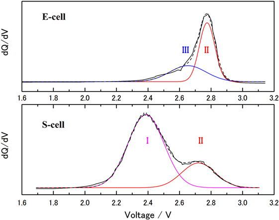
Figure 9. dQ/dV plot of the charge process for S-cell (bottom) and E-cell (upper). Gaussian peak fitting was performed onto the dQ/dV data with R2 > 0.998. Each peak consists of I: main red-ox reaction of sulfur, II: red-ox capacity with poly-condensation of Li3PS4, and III: red-ox capacity of LiI.
Although there are some unclear points (e.g., the exact formation of the anions in the cathode composite), LiI and two electron redox of Li3PS4 (3 ≧ x ≧ 2) were suitable for considering the reversible capacity of the LiI–Li3PS4, which was used in this study. Because of the unusual DSC peaks observed in the C–S–SE composite, carbon and sulfur might also contribute to the highly complicated active material. Although further investigation is required to clarify this redox system, it is clear that the solid-state electrolyte, LiI–Li3PS4, has scope for use in real cell reactions.
Conclusion
A sulfide-based SE, amorphous LiI–Li3PS4, was prepared by mechanical milling. The ionic conductivity was determined to be 1.2 mS cm−1 at 25°C with an activation energy of 29.1 kJ mol−1. We have demonstrated the successful fabrication of two types of lithium secondary cells using LiI–Li3PS4. In the NCA-cell, the cell performance improved in comparison to the Li3PS4 adopted cell in our previous study, except for the cycle ability. Due to its poor electrochemical stability of LiI–Li3PS4, the cycle performance was unsatisfactory in the 4-V system. On the contrary, the cycle performance was significantly improved in the S-cell using the same electrolyte compared to our previous study. The high coulombic efficiency above 99.9% during charge–discharge cycle test was verified in the S-cell. This indicates that the cell can basically operate 1000 cycles without reserve lithium capacity in terms of the figure of merit.
Interestingly, the C–SE composite electrochemically reacted and clearly showed a reversible capacity in the potential range of 3.1–1.3 V versus Li/Li+. Although the exact reaction needs to be clarified, the stable capacity was about 260 mAh g−1. Also, a cooperative reaction between sulfur, LiI, and Li3PS4 was observed in the C–S–SE composite. The coulombic efficiency was extremely high, even though some complex reaction was expected. Also, no evidence for a polysulfide redox shuttle was observed within 100 cycles. These facts indicate that the solid-state electrolyte and its adopted system is one of the most promising approaches for producing high-capacity lithium secondary batteries.
Author Contributions
YA and SI proposed the idea and strategy for the experimental work. SI, SF, RO, and TY designed the experiments and performed the synthesis and characterization of the samples in addition to the electrochemical measurements. The experimental data were analyzed and the manuscript was written by YA and TW. The entire project was coordinated by YP and SD.
Conflict of Interest Statement
The authors declare that the research was conducted in the absence of any commercial or financial relationships that could be construed as a potential conflict of interest.
Acknowledgments
This work is financially supported by Samsung Electronics. The authors acknowledge Prof. Machida (Konan University) for valuable discussion on the solid electrolyte and also express their sincere gratitude to Prof. Price (Western Sydney University) for improving the manuscript.
References
Bates, J. B., Dudney, N. J., Gruzalski, G. R., Zuhr, R. A., Choudhury, A., Luck, C. F., et al. (1993). This volume contains the Proceedings of the 6th International Meeting on Lithium Batteries Fabrication and characterization of amorphous lithium electrolyte thin films and rechargeable thin-film batteries. J. Power Sources 43, 103–110. doi: 10.1016/0378-7753(93)80106-Y
Hakari, T., Nagao, M., Hayashi, A., and Tatsumisago, M. (2015). All-solid-state lithium batteries with Li3PS4 glass as active material. J. Power Sources 293, 721–725. doi:10.1016/j.jpowsour.2015.05.073
Ito, S., Fujiki, S., Yamada, T., Aihara, Y., Park, Y., Kim, T. Y., et al. (2014). A rocking chair type all-solid-state lithium ion battery adopting Li2O-ZrO2 coated LiNi0.8Co0.15Al0.05O2 and a sulfide based electrolyte. J. Power Sources 248, 943–950. doi:10.1016/j.jpowsour.2013.10.005
Kamaya, N., Homma, K., Yamakawa, Y., Hirayama, M., Kanno, R., Yonemura, M., et al. (2011). A lithium superionic conductor. Nat. Mater. 10, 682–686. doi:10.1038/nmat3066
Lin, Z., Liu, Z., Fu, W., Dudney, N. J., and Liang, C. (2013). Lithium polysulfidophosphates: a family of lithium-conducting sulfur-rich compounds for lithium-sulfur batteries. Angew. Chem. Int. Ed. 52, 7460–7463. doi:10.1002/anie.201300680
Mercier, R., Malugani, J.-P., Fahys, B., and Robert, G. (1981). Proceedings of the International Conference on Fast Ionic Transport in Solids Superionic conduction in Li2S-P2S5-LiI glasses. Solid State Ionics 5, 663–666. doi:10.1016/0167-2738(81)90341-6
Nagata, H., and Chikusa, Y. (2014). A lithium sulfur battery with high power density. J. Power Sources 264, 206–210. doi:10.1016/j.jpowsour.2014.04.106
Ogawa, M., Kanda, R., Yoshida, K., Uemura, T., and Harada, K. (2012). High-capacity thin film lithium batteries with sulfide solid electrolytes. J. Power Sources 205, 487–490. doi:10.1016/j.jpowsour.2012.01.086
Ohtomo, T., Hayashi, A., Tatsumisago, M., and Kawamoto, K. (2013). All-solid-state batteries with Li2O-Li2S-P2S5 glass electrolytes synthesized by two-step mechanical milling. J. Sol. St. Electrochem. 17, 2551–2557. doi:10.1007/s10008-013-2149-5
Rangasamy, E., Liu, Z., Gobet, M., Pilar, K., Sahu, G., Zhou, W., et al. (2015). An iodide-based Li7P2S8I superionic conductor. J. Am. Chem. Soc. 137, 1384–1387. doi:10.1021/ja508723m
Rao, B. M. L., Silbernagel, B. G., and Jacobson, A. J. (1978). Evaluation of solid electrolytes for high temperature lithium batteries: a preliminary study. J. Power Sources 3, 59–66. doi:10.1016/0378-7753(78)80005-6
Scrosati, B., and Garche, J. (2010). Lithium batteries: status, prospects and future. J. Power Sources 195, 2419–2430. doi:10.1016/j.jpowsour.2009.11.048
Tatsumisago, M., Hama, S., Hayashi, A., Morimoto, H., and Minami, T. (2002). New lithium ion conducting glass-ceramics prepared from mechanochemical Li2S-P2S5 glasses. Solid State Ionics 15, 635–640. doi:10.1016/S0167-2738(02)00509-X
Weppner, W. (1981). Proceedings of the International Conference on Fast Ionic Transport in Solids Trends in new materials for solid electrolytes and electrodes. Solid State Ionics 5, 3–8. doi:10.1016/0167-2738(81)90186-7
Keywords: solid-state battery, solid electrolyte, lithium–sulfur batteries, lithium secondary batteries, sulfide electrolyte, catholyte
Citation: Aihara Y, Ito S, Omoda R, Yamada T, Fujiki S, Watanabe T, Park Y and Doo S (2016) The Electrochemical Characteristics and Applicability of an Amorphous Sulfide-Based Solid Ion Conductor for the Next-Generation Solid-State Lithium Secondary Batteries. Front. Energy Res. 4:18. doi: 10.3389/fenrg.2016.00018
Received: 01 February 2016; Accepted: 18 April 2016;
Published: 13 May 2016
Edited by:
Fuminori Mizuno, Toyota Research Institute of North America, USACopyright: © 2016 Aihara, Ito, Omoda, Yamada, Fujiki, Watanabe, Park and Doo. This is an open-access article distributed under the terms of the Creative Commons Attribution License (CC BY). The use, distribution or reproduction in other forums is permitted, provided the original author(s) or licensor are credited and that the original publication in this journal is cited, in accordance with accepted academic practice. No use, distribution or reproduction is permitted which does not comply with these terms.
*Correspondence: Yuichi Aihara, yuichi.aihara@samsung.com