A Review of the Emerging Field of Underwater Mass Spectrometry
 Emily J. Chua1*
  William Savidge2
  R. Timothy Short3
  Andres M. Cardenas-Valencia3
  Robinson W. Fulweiler1,4
- 1Department of Earth and Environment, Boston University, Boston, MA, USA
- 2Skidaway Institute of Oceanography, University of Georgia, Savannah, GA, USA
- 3Sensing and Domain Awareness Laboratory, SRI International, St. Petersburg, FL, USA
- 4Department of Biology, Boston University, Boston, MA, USA
Mass spectrometers are versatile sensor systems, owing to their high sensitivity and ability to simultaneously measure multiple chemical species. Over the last two decades, traditional laboratory-based membrane inlet mass spectrometers have been adapted for underwater use. Underwater mass spectrometry (UMS) has drastically improved our capability to monitor a broad suite of gaseous compounds (e.g., dissolved atmospheric gases, light hydrocarbons, and volatile organic compounds) in the aquatic environment. Here we provide an overview of the progress made in the field of UMS since its inception in the 1990s to the present. In particular, we discuss the approaches undertaken by various research groups in developing in situ mass spectrometers. We also provide examples to illustrate how underwater mass spectrometers have been used in the field. Finally, we present future trends in the field of in situ mass spectrometry. Most of these efforts are aimed at improving the quality and spatial and temporal scales of chemical measurements in the ocean. By providing up-to-date information on UMS, this review offers guidance for researchers interested in adapting this technology as well as goals for future progress in the field.
Introduction
The oceans comprise the largest ecosystem on Earth and play a key role in regulating our climate, yet they remain largely understudied. In particular, our knowledge of ocean biogeochemical cycles is hindered by our limited capacity for sustained measurements. Additional challenges arise since analytes of interest to scientists studying both natural processes and anthropogenic impacts on the ocean exist in a variety of states (e.g., volatile, nonvolatile, and complexed) with concentrations spanning 15 orders of magnitude (from a minimum of nearly 10−15 M; Johnson et al., 1992). Furthermore, chemical variability is temporally dynamic and can occur over spatial distances of <1 mm to over tens of thousands of kilometers (Johnson et al., 1992). Discrete sampling rarely captures this range of variation in ocean properties. Consequently, there is an acute need for in situ sensors that can measure a variety of key chemical species [e.g., oxygen, nutrients, biogenic gases, and dissolved inorganic carbon (DIC)] on spatial and temporal scales that match the scales of the processes being investigated. Ideally, these sensors should have a large dynamic concentration range, excellent detection limits, quick response time, high stability, and resistance to fouling (Moore et al., 2009; Bell et al., 2012).
Mass spectrometry (MS) is regarded as one of the most versatile analytical methods currently available and is well suited to meet many of these demands. MS provides elemental, structural, and isotopic information on a wide range of chemical species, quantifies known compounds, and can identify unknown compounds (Maher et al., 2015). Coupling the analytical power of MS to the inherent advantages of in situ sampling is a logical and compelling step forward in the study of ocean chemistry. Such an undertaking is no trivial task, since conventional mass spectrometers are typically large bench-top instruments.
The field of underwater mass spectrometry (UMS) has evolved to address this research need and to date can quantify gaseous compounds in the ocean. To the best of our knowledge, all current underwater mass spectrometers are based on membrane inlet mass spectrometry (MIMS) technology. In MIMS, samples can be obtained directly from the environment without any intervening manual sample collection or manipulation. The sampling interface is a hydrophobic semi-permeable membrane. A vacuum is applied to the instrument side of the membrane, allowing gases and small volatile organic molecules to pass directly from the external environment into the mass spectrometer. Because the instrument samples continuously, very high sample throughput rates are possible. Additionally, prolonged in situ deployments potentially allow for more sophisticated statistical analyses of environmental signals (e.g., Mills and Fones, 2012). UMS has already been put to practical use. For example, these systems have been placed on mobile platforms to produce two- and three-dimensional underwater maps of chemical distributions (e.g., Wenner et al., 2004; Camilli et al., 2010; Gentz and Schlüter, 2012). Other UMS systems have been developed to target understudied areas of ocean chemistry, such as in situ isotope ratios (Camilli and Duryea, 2009) and porewater composition (Bell et al., 2012).
The purpose of this review is to describe the current status, recent advancements, and potential future trends in the field of UMS, focusing in particular on underwater MIMS technology. We provide a summary of the successful UMS systems developed and deployed by various research groups, including details on detection limits, power requirements, overall robustness, and the effect of physical factors on instrument response. We also highlight common trends between platforms and discuss promising areas of growth.
Underwater Mass Spectrometry (UMS)
UMS vs. Contemporary Ocean Sensors
In the ocean, many chemical species of interest are present as dissolved gases and volatile compounds. Conventional ex situ water sampling techniques (e.g., via Rosette sampler followed by analysis via gas chromatography) require the manual collection, storage, and transport of samples to the laboratory and thus are typically labor-intensive and time-consuming. Worse, sampling artifacts are prevalent due to the physical and chemical changes such as degassing and biological degradation that may occur during transport (Camilli and Hemond, 2004). For example, pressure and temperature have a pronounced effect on methane solubility, and so upon retrieval of methane-saturated water samples from the deep ocean, methane rapidly outgasses to the atmosphere (Wankel et al., 2010). As an additional challenge, point sources such as seeps (both natural and anthropogenic) have high spatial and temporal heterogeneity, and this patchiness requires the ability to sample at high resolution in both space and time.
Many in situ techniques such as oxygen optodes and tin oxide (SnO2) sensors have been developed to overcome the limitations associated with off-site sampling (Table 1). In recent years, several groups have produced methane sensors with impressively low detection limits (at the nM level) using innovative techniques involving surface plasmon resonance (Boulart et al., 2013) and a highly-sensitive waveguide Mach-Zehnder interferometer (Dullo et al., 2015; Lindecrantz, 2016). These various sensors have helped advance our understanding of the ocean, but have their own drawbacks. For one, they are commonly limited to detecting one or a few gas species at a time, meaning that multiple sensors are required to survey a broad spectrum of gases at once (Table 1). Furthermore, some single-parameter measurement techniques such as SnO2 sensors suffer from a lack of selectivity. For example, the METS methane sensor responds to any kind of gas that can be oxidized, and so all gases that pass through the membrane (e.g., dissolved oxygen) can interfere with methane measurements (Lawrence, 2006; Boulart et al., 2010). Sensitivities are typically about 1 ppm (Camilli and Hemond, 2004) and response times are often on the order of minutes (Table 1). Volatile organic compounds (VOCs) such as toluene, benzene, and dimethylsulfide (DMS) may be detected via IR spectroscopy, but this method is restricted to the surface ocean and coastal waters (Table 1).
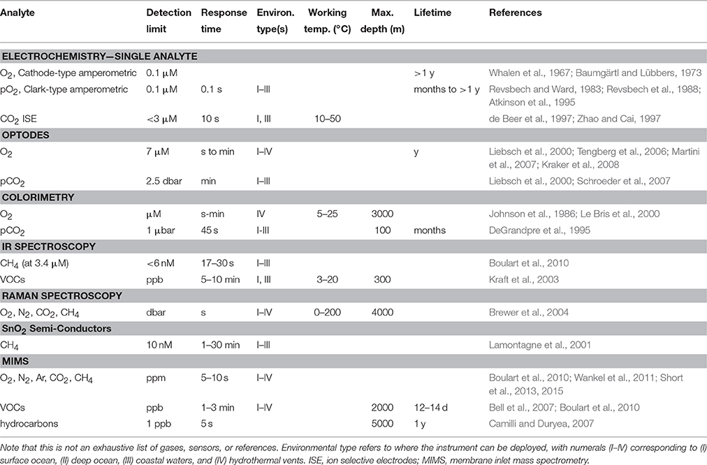
Table 1. Examples of current in situ techniques for measuring dissolved gases and volatile organic compounds (VOCs) in the aquatic environment.
With UMS, a range of species can be analyzed using a single system. This capability alone sets it apart from other in situ techniques. UMS systems can detect many dissolved gases at the ppm level and VOCs at the ppb level within a matter of seconds or minutes (Table 1). Deployment of UMS systems on mobile platforms such as autonomous underwater vehicles (AUVs) and remotely operated vehicles (ROVs) is already a reality (Figure 1). Such a configuration allows for continuous three-dimensional measurements of a variety of gases and other volatile species in real time, as well as the potential for high-resolution mapping. Using UMS, one can also track the dynamics of biogeochemical changes (Wankel et al., 2010). For example, dissolved O2/Ar ratios in the surface ocean are indicative of net community production (NCP), and changes in this ratio have been used to track alterations in NCP in the eastern equatorial Pacific (Kaiser et al., 2005). The sophistication of the measurements enabled by UMS makes it a valuable in situ technique to pursue.
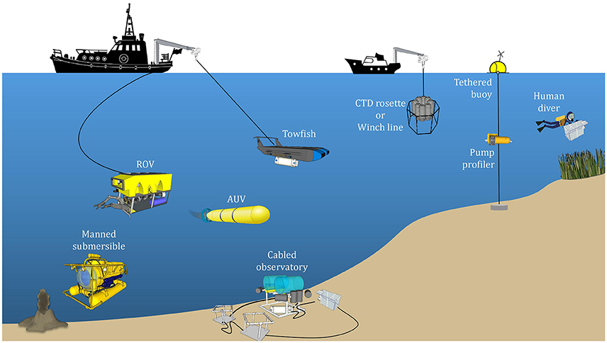
Figure 1. Schematic of the various platforms on which underwater mass spectrometers can be deployed. The choice of platform depends on the length of sampling and the marine environment to be sampled, which may be broadly classified into the surface ocean, coastal waters, deep ocean, and seafloor exploration (e.g., hydrothermal vents). Images of the boats courtesy of openclipart.org. Images of the boat cranes and pulleys, remotely operated vehicle (ROV), manned submersible, cabled observatory, towfish, CTD rosette and winch line, tethered buoy, pump profiler, and human diver courtesy of 3D Warehouse (3dwarehouse.sketchup.com), copyright 2016 Trimble Navigation Limited. Images of the grass and volcano courtesy of the Integration and Application Network, University of Maryland Center for Environmental Science (ian.umces.edu/symbols/).
Membrane Inlet Mass Spectrometry (MIMS)
A primary consideration in applying mass spectrometry underwater is how dissolved analytes are introduced into the high vacuum of the mass spectrometer. The sample introduction method must be simple yet robust. MIMS, pioneered over six decades ago by Hoch and Kok (1963), is now the technique routinely employed in UMS systems. In MIMS, a volatile sample passes directly from the environment into the mass spectrometer through a selectively permeable membrane. MIMS requires minimal-to-no sample preparation and employs simple and robust inlets. It enables simultaneous measurement of multiple chemical species with unique mass-to-charge (m/z) ratios from a single sample. Analyte concentrations can be measured from the parts-per-hundred to parts-per-trillion levels on timescales of a few seconds to minutes (Johnson et al., 2000). The membrane interface significantly reduces the gas load on high-vacuum systems (Wenner et al., 2004), and the ability for rapid, in situ measurements eliminates some sampling and all storage artifacts (Hemond and Camilli, 2002).
Performance of Membrane Materials
Membranes act as the physical barrier between the sample stream and the vacuum of the mass spectrometer. They are typically ~0.1 mm thick and made of silicone polymers (Johnson et al., 2000). Polydimethylsiloxane (PDMS) is the most frequently-used membrane material in UMS (Table 2) because it has a high permeability for dissolved gases and VOCs, but a very low permeability for water and salts (Wenner et al., 2004). It has been shown, however, that the permeability of certain PDMS membranes is strongly dependent on hydrostatic pressure since PDMS is a flexible elastic polymer (Bell et al., 2007). Changes in hydrostatic pressure can cause the internal membrane space to expand or contract, altering the spacing through which gaseous analytes are able to permeate. This permeability response may be different under increasing or decreasing pressure, a phenomenon known as hysteresis.
Table 2. Membrane inlet mass spectrometry (MIMS) and sampling interface specifications for current underwater mass spectrometry (UMS) systems for in situ measurements of dissolved gases and volatile organic compounds (VOCs).
Underwater MIMS researchers have recently begun to evaluate alternative membrane materials that do not exhibit hysteresis in gas permeation under pressure. Wankel et al. (2011) found Teflon amorphous fluoroplastics (AF), a more rigid material, to be resistant to pressure changes. During multiple laboratory calibrations in which they subjected Teflon AF membranes to large ranges of hydrostatic pressure, relative changes in ion intensity always remained <10%, consistent with another study by Pinnau and Toy (1996). Teflon AF has the additional benefits of excellent chemical resistance and high permeability to a range of gases (e.g., He, H2, N2, and O2; Pinnau and Toy, 1996). As another alternative, Miranda et al. (2011) developed polysiloxane nano-composite (PNC) membranes created by coating a thin polysiloxane film to the surface of an anodic aluminum oxide substrate. They found that these membranes minimize film compression and hysteresis effects. Subsequent laboratory tests showed that PNC membranes have a much higher mechanical strength than PDMS membranes, exhibit little deviation in gas permeation at elevated hydrostatic pressure, and are substantially less affected by hysteresis.
Physical Configuration
Membranes may take on different physical geometries within the mass spectrometer and must be properly supported (i.e., provided with a porous solid backing; Figure 2). Otherwise, they will rupture from hydrostatic pressure, flood the vacuum system, and destroy the instrument. Many UMS systems employ cylindrical capillaries which are located within, or mounted on, a porous sintered rod (Table 2). As sample water flows past the tubular-shaped membrane, the flow of gas permeating through the membrane may be inside out (in the former case; Figure 2A), or outside in (in the latter case; Figure 2B). Another approach is to use a flat plate geometry supported by a porous frit (Figure 2C). Sample fluid flows directly across the flat membrane, which preferentially permits gaseous analytes to permeate through.
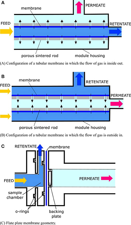
Figure 2. The flow of gas through the membrane (dark blue) is driven by differential pressure in the filtration modules. The “permeate” (also known as the “filtrate”) is the part of the liquid that passes through the membrane. The “retentate” (also called the “concentrate”) is the part of the liquid that does not pass through the membrane. In the case of membrane inlet mass spectrometry (MIMS), the permeate is the gas sample, which is to be delivered to the mass spectrometer, while the retentate is the “waste” water, which is to be exhausted from the module housing. In (A,B), the membrane is supported by a hollow sintered tube. Another common configuration is a sintered rod. Permeate flow through the membrane and conduits of the rod is represented by black arrows. In (C), the membrane is supported by a porous frit, and sample fluid impinges directly onto the membrane.
To improve sensitivity as well as lower detection limits by enhancing the flux of analytes into the vacuum system, it is tempting to increase the surface area and decrease the thickness of the membrane interface. These modifications, however, also increase the introduction of water vapor into the system. An upsurge of water vapor in the vacuum system may interfere with peaks of interest (e.g., methane) in the mass spectrum and may overload the ion source. It will also result in higher vacuum pumping demands on the system. Through a typically empirical process and for each system, one must choose a membrane configuration that provides an optimum balance between the introduction of analytes and water vapor.
Membrane Permeability
According to Fick's first law, a simple linear relationship exists between analyte flux and partial pressure or fugacity gradient (Bell et al., 2007). However, membrane permeability can change when a polymer undergoes compression, swelling, competitive sorption, or changes in geometry (Fujita, 1961). Significant swelling and competitive sorption are not expected when sampling water. Proper membrane support can prevent significant changes in system geometry. Thus, for aqueous samples, the primary influences on membrane behavior are temperature, hydrodynamics at the sample/membrane interface, and pressure.
Temperature
Decreasing the temperature causes the permeability to decrease. This can be seen from the Arrhenius relation (LaPack et al., 1990), in which the permeability, P at temperature, T is given by
where P0 is the initial permeability at some initial temperature, T0, Ep is the permeation activation energy, and R is the universal gas constant (8.314 J mol−1 K−1). A simple solution to avoiding temperature effects is to ensure that the membrane inlet maintains a constant temperature (Bell et al., 2007), for example by heating sample water to a preset temperature.
Hydrodynamics
At low flow rates, fluid turbulence is insufficient to disrupt boundary layer growth at the sample/membrane interface and as a result, this region of reduced mixing can limit the rate of gas transport to the membrane surface. When the rate of gas transport through the membrane exceeds the rate of transport to the membrane, the analyte can become depleted at the membrane-fluid interface. This effect lowers the observed MIMS response. Increasing sample flow rate through restrictive geometries can mitigate this issue by reducing boundary layer thickness at the inlet (Bell et al., 2011). Higher sample flow rates, however, increase the power needed to heat the sample water. A balance between these competing effects must be established to optimize instrument performance.
Hydrostatic pressure
Pressure variations alter membrane permeation, causing changes in the magnitude of ion intensity independent of actual analyte concentration. In a laboratory experiment involving a PDMS membrane, Bell et al. (2007) measured MIMS ion currents for a number of dissolved gases and VOCs over a range of hydrostatic pressures (0–20 MPa) at constant temperature and salinity (Figure 3). For light atmospheric gases as well as H2S and DMS, ion current decreased with increased pressure due to a decline in membrane permeability (Figures 3A–G). In contrast, for larger nonpolar permeants (i.e., the VOCs chloroform and toluene), ion current had little change or increased at higher pressure (Figures 3H,I). In addition, the flux of chemicals into the mass spectrometer through the PDMS membrane depended on whether the membrane was subjected to increasing or decreasing pressure. The resulting hysteresis in the membrane response can produce significant uncertainties in measurements. To correct for changes in gas diffusion with pressure, Bell et al. (2007) developed a semi-empirical model to describe the relationship between pressure and membrane permeability. For small permeants, the permeability at a given pressure is a function of three variables: the fraction of an analyte's permeability that is independent of pressure (specific to each permeant), a term related to membrane compressibility (approximately constant for different permeants), and the given pressure. For large permeants (e.g., VOCs), a molar volume correction term must be included which takes into account the difference between a gas partial molar volume in the membrane and liquid phase, as well as the temperature. Bell et al. (2007) applied these models to gas profiles collected in the Gulf of Mexico down to 500 m depth (in which the membrane inlet was kept at a constant temperature and the salinity was essentially constant over the depths profiled) and compared the resulting profiles to those determined with an independently deployed CTD and oxygen sensor. Good agreement between the pressure-corrected UMS oxygen data and oxygen sensor measurements demonstrated that pressure and hysteresis effects can be accounted for quantitatively in the upper 500 m. As UMS continues to be taken to greater depths, Bell et al. (2007) stress that their pressure calibration procedure should likewise be extended.
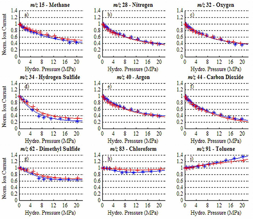
Figure 3. Ion current dependency on hydrostatic pressure for a range of dissolved gases and VOCs at 35°C: (a) methane, (b) nitrogen, (c) oxygen, (d) hydrogen sulfide, (e) argon, (f) carbon dioxide, (g) dimethyl sulfide, (h) chloroform, (i) toluene. Blue (*) data were obtained as hydrostatic pressure was increased and red (+) data as pressure was decreased. Reprinted with permission from Bell et al. (2007). Copyright 2007 American Chemical Society.
Following Bell et al.'s (2007) approach, Wankel et al. (2010) conducted pressure calibrations for their PDMS membranes using methane dissolved in seawater over a range of in situ pressures. They used these results to develop an empirical correction as described by Bell et al. (2007). Although, Wankel et al.'s (2010) calibration corrected for implicit changes in membrane behavior for fluids sampled at ~2300 m, they noted that the dataset was collected at a relatively constant depth, and so effects caused by differential pressure or temperature were negligible.
Time Delays
Since polymeric membranes effectively act as a diffusion layer to chemicals permeating into the mass analyzer, the resulting flux through the membrane is not instantaneous but rather a function of time. For PDMS membranes, this delayed time response typically ranges from about 10 s for light stable gases to several min for higher molecular weight VOCs. Consequently, during deployments of UMS systems the timing and time resolution of measurements are affected. For deployments on moving platforms (e.g., ROVs and AUVs), time response delays translate into a problem of geolocation (matching changes in MS signals with the location of the UMS system) and spatial resolution. In addition, if the UMS system transits a narrow band of high concentration analytes (e.g., in a seep plume), the flux of analytes through the membrane does not have time to reach steady-state conditions, making calculations of analyte concentrations difficult. Short et al. (2006) and Janfelt et al. (2007) discuss these issues in more detail and offer solutions to calculate analyte concentrations under these conditions. Despite recent advances in UMS data processing, more work is needed to enable the in situ validation of these algorithms, implement them in real time, and accurately represent complex chemical concentration profiles in the water.
Field-Portable Mass Analyzers
In situ mass spectrometry analysis is only feasible if the requisite instrumentation is field-portable, and so the mass analyzer must be miniaturized (Badman and Cooks, 2000; Ouyang and Cooks, 2009; Snyder et al., 2015). Magnetic sector, time-of-flight, linear quadrupole, ion trap, and cycloidal mass analyzers are the types of mass analyzers that have been miniaturized successfully.
Most UMS systems employ linear quadrupole mass filters (e.g., Short et al., 1999; McMurtry et al., 2005; Schlüter and Gentz, 2008; Wankel et al., 2010) which are robust, compact, and relatively inexpensive (McMurtry et al., 2005). The power requirements for quadrupole mass filters contribute significantly to the overall system's power consumption, as they must operate using rather high direct current (DC) and radio frequency (RF) voltages applied to the four rods of the analyzer.
Cycloidal mass analyzers have been incorporated into UMS systems by Hemond and Camilli (2002), Camilli and Hemond (2004), Camilli and Duryea (2007), and Hemond et al. (2008). Crossed electric and magnetic fields are used to impart trajectories to the sample ions, which allows for perfect direction and velocity focusing, resulting in a relatively compact analyzer. No RF generator is required, only modest DC voltages at low current are needed, and a permanent magnet may be used to generate a magnetic field, further minimizing power consumption (Camilli and Hemond, 2004).
Ion traps have also been used in UMS systems, and have a wider mass range than linear quadrupoles or small cycloidal analyzers (650 amu vs. a few hundred amu; McMurtry et al., 2005). However, the membrane inlet typically limits the range of m/z of compounds introduced into the mass spectrometer to <300 amu, so the full range of the ion trap cannot be utilized. Ion traps are highly sensitive, with detection limits up to 20 times better than some quadrupole mass filters (Short et al., 2001), which is especially useful in environmental and trace monitoring. Ion traps can operate at even higher pressures than linear quadrupoles, and they can perform multiple stages of mass spectrometry with no modifications (Badman and Cooks, 2000). Conventional size ion traps require high RF fields, however, and have much higher power requirements than linear quadrupoles, adversely affecting deployment length (McMurtry et al., 2005).
Design Hurdles and Solutions
Traditional, laboratory-based MIMS has been adapted for shipboard operation by continuous pumping of seawater past a membrane (Tortell, 2005). While this approach allows for continuous underway surveys of volatiles dissolved in seawater, sampling is restricted to shallow depths. To meet the demands of aquatic sampling, many in situ mass spectrometers are miniaturized versions of their laboratory-based counterparts fitted within a robust protective “pressure housing” capable of withstanding high hydrostatic pressures. The overall layout of UMS systems is generally quite similar (Figure 4). By and large, UMS systems are designed to be modular, which allows for easier reconfiguration of different components. Sample introduction from the outside environment to the instrument is accomplished via a membrane inlet typically using a PDMS membrane (Table 2), and signals are obtained with a mass analyzer of choice (Table 3). In order to maintain the high vacuum required for analysis, a roughing pump-turbomolecular pump combination is typically used. Mass ranges are typically 1–200 amu (Table 3), allowing for the quantification of major gases in the ocean (Table 4). Detection limits can be on the ppb level (Table 3), allowing for measurement at trace levels. More recent platforms are capable of deep sea measurements (>2000 m; Table 4). These in situ instruments have been deployed on a wide variety of platforms, including winch lines, sampling Rosette frames, tethered buoys, unmanned submersibles such as AUVs and ROVs, and even by human divers (Figure 1).
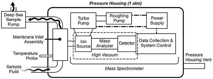
Figure 4. General layout of a generic underwater mass spectrometry (UMS) system. Sample fluid is pumped past the membrane inlet assembly which extracts gaseous analyte. The gas sample then enters the mass spectrometer where sample ionization and detection can take place. The MS signal is digitized, analyzed, and stored by an onboard computer. A roughing pump-turbo pump combination maintains the high vacuum within the pressure housing. Power is supplied through either a battery or an external power source.
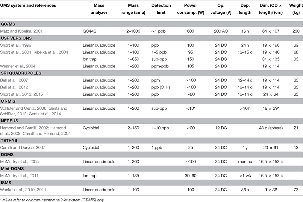
Table 3. Operational specifications for current underwater mass spectrometry (UMS) systems for in situ measurements of dissolved gases and volatile organic compounds (VOCs).
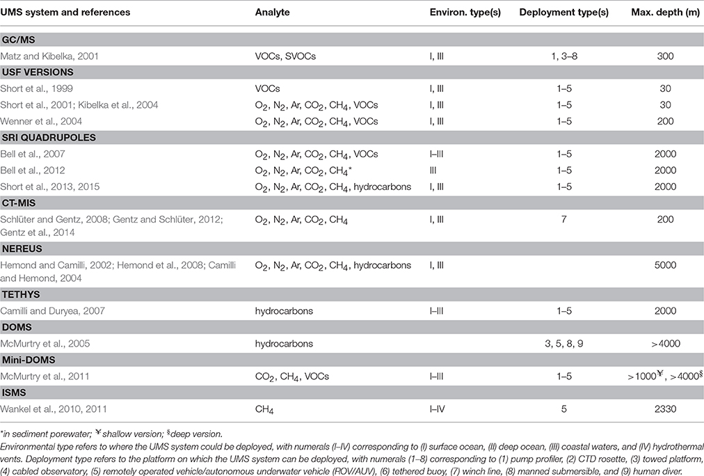
Table 4. Sampling specifications for underwater mass spectrometry (UMS) systems for in situ measurements of dissolved gases and volatile organic compounds (VOCs).
Hydrostatic Pressure and Vacuum Systems
Truly in situ mass spectrometers must operate underwater, where the hydrostatic pressure increases about 105 Pa every 10 m. To add to the challenge, certain components of the mass spectrometer (i.e., the ion source, mass analyzer, and detector) only function in a high vacuum (<10−5 Torr). Achieving this places severe demands on the vacuum pumps since analytes must be transported from the external marine environment, which is highly pressurized at great depths, into the vacuum system of the instrument. Accordingly, the success of a UMS system depends largely on the efficiency of its pumping system.
Establishing and maintaining a high vacuum is possible with mechanical, throughput vacuum pumps. This process involves two stages: a roughing pump (usually a diaphragm pump) first brings the pressure down to about 10−1 Torr, and then a turbomolecular (turbo) pump further drives the pressure down to 10−5–10−7 Torr (McMurtry et al., 2005). Turbo pumps can create a much higher vacuum range but cannot exhaust directly to atmospheric pressure. The exhaust from the throughput pumping system can either be vented directly into the UMS system pressure housing (which is initially at 1 atmosphere), or routed to a separate vessel (which is possibly initially evacuated) within the pressure housing. Exhausting within the pressure housing and including some desiccant materials in the pressure housing to keep humidity relatively low have enabled the deployment of UMS systems for about 2 weeks, since the pressure increase from vacuum pump exhaust over this time period does not build up sufficiently to degrade vacuum pump performance (Short et al., 2011). Over longer deployments, pressure build-up from vacuum exhaust will ultimately degrade pumping performance.
Most UMS systems have traditionally employed this roughing pump-turbo pump combination. Some research groups (Hemond and Camilli, 2002; McMurtry et al., 2012) have experimented with alternate entrainment and trapping pumping system. Ion pumps such as sputter-ion pumps use gettering or a chemical and ionization interaction to produce a vacuum. Under high-vacuum conditions, a surface can hold large quantities of gas compared to the amount of gas present (Schulz, 1999). Placing a getter (i.e., a deposit of reactive material, such as titanium) inside the vacuum allows for the maintenance of a vacuum, since gas molecules striking the getter material combine with it chemically or by absorption. When ions strike and are buried inside the cathode they eject (sputter) some of the getter material coating the cathode. It is necessary to periodically clean and re-apply fresh getter material, and so ion pumps have a finite lifetime of 400 h while operating at 10−5 Torr and 40,000 h while operating at 10−7 Torr (Schulz, 1999). The vacuum housing must also be pre-pumped to high vacuum before starting these types of pumps. Diode ion pumps and non-evaporable getter (NEG) ion pumps are examples of sputter-ion pumps that have been employed in UMS systems.
Power Requirements
The length of deployment for a given UMS system is often dependent on its power needs and the type of power available. Instruments cabled to shore power can theoretically operate indefinitely and are only limited by other aspects of their systems. Similarly, instruments attached to cabled ROVs may be constrained by the operational limits of the ROV itself, but not by the power demands of the UMS system. Many UMS deployments, however, have been powered by internal or external battery packs, and the capacity of the battery bank effectively determines the endurance of the instrument. McMurtry et al. (2005) experimented with a fuel cell power source, but this technique still employs a finite power source. In a field deployment, Bell et al. (2012) successfully extended the endurance of their battery-powered UMS system from a 12-h battery charge to a 54-h continuous operational deployment by incorporating a renewable battery system, which required a manual exchange of batteries with the buoy-cabled UMS system twice daily.
There are many trade-offs between instrument performance and power consumption. Further miniaturization and simplification of UMS components will lower overall power demands. On the other hand, refining systems to make better and more sophisticated measurements, such as controlling more sampling parameters and environmental conditions, usually increases the power consumption of systems. For instance, there is a growing demand for acidifying samples in-line to convert carbonate and bicarbonate pools into CO2, or for cryotrapping water vapor in the vacuum behind the membrane to improve detection limits and signal stability, both of which will increase power needs. Some systems work around increased power demand issues by temporarily turning off when not in sample mode. For example, the Deep Ocean Mass Spectrometer (DOMS) samples for brief periods and then switches to “sleep” mode, during which time power requirements are very low (McMurtry et al., 2005, 2011). Deployments of several months to a year using battery power are theoretically possible using this technique.
Fouling
Biofouling is a concern whenever and wherever oceanographic instrumentation is deployed. With UMS, the areas of concern are the membrane as well as any other plumbing that is upstream of the inlet membrane, particularly the sample lines. Bacterial films on internal surfaces can produce or consume gases independently of the environment being sampled, and direct fouling of the membrane will change its permeation characteristics. Larger organisms may quickly grow over and occlude sampling ports. Physical fouling, which can occur in environments with high sediment loads, may also present a risk of clogging sampling inlets (e.g., Martini et al., 2007). Clogging can reduce the sample flow rate past the membrane, causing boundary layer effects and hence degrading the quality of measurements. Fouling is a major challenge in coastal waters due to the high rates of productivity and abundance of particulate matter (Moore et al., 2009).
No system exists that can absolutely guarantee an absence of biofouling—however, a liberal use of copper (tubing, tapes, meshes, and frits) on exposed surfaces will greatly reduce the problem. Periodic introductions of small amounts of acid can also mitigate biofouling within sample lines (Bell, personal communication). To our knowledge, the effects of microbial colonization of sampling interfaces in UMS have not been examined directly.
Sampling Environment
All UMS instruments consume gases, and most versions pump water past the sampling membranes. Thus, while the underwater environment can be harsh on the instrument, deploying the instrument can also disturb the sampling environment. In environments where gas transport and renewal of the sampled volume is limited (e.g., strong pycnoclines, microbial mats, porewaters, sea ice) the act of sampling has the potential to generate artifacts if sample pumping rates change the natural rates of supply of substrates. For example, microbial rate processes including substrate consumption can be very sensitive to changes in local fluid flux (e.g., Huettel et al., 2014). In such environments, adopting adaptive sampling strategies that are sensitive and responsive to intrinsic gas or fluid renewal rates may alleviate sampling artifacts.
UMS System Calibration
In order to determine in situ analyte concentrations, UMS systems must be calibrated for the specific compounds that they will measure in the field. One should also verify that the system's response is linear within the range that it is expected to encounter in the field. If the actual concentrations in the field exceed the range used in the pre-deployment calibration then the membrane could possibly become saturated, which would likely lead to inaccurate results. The exact calibration procedure will vary depending on the system. Here, we present a generic protocol based on those described by various authors (Bell et al., 2007; Schlüter and Gentz, 2008; Wankel et al., 2011; Camilli et al., 2015).
To establish gas and VOC sensitivities and baselines, a calibration is run both before and after a deployment using equilibrated gas and VOC seawater standards. For dissolved gases, seawater is equilibrated for more than an hour with gas mixtures containing certified mole fractions of the gases of interest. The salinity and temperature of the solution must be known in order to calculate exact gas concentrations (Weiss, 1970, 1974; Wiesenburg and Guinasso, 1979; Garcia and Gordon, 1992; Hamme and Emerson, 2004). For calibration of VOCs, initial standards are created by dissolving each VOC in a solvent (e.g., methanol) and then subsequent standards are created via serial dilutions of the stock solution in water. Concentrations are chosen to create signals that are at least an order of magnitude above baseline values for each ion (Bell et al., 2007). Baseline values are determined by reducing the sample flow rate to zero, allowing the aqueous sample in contact with the membrane to degas completely. The calibrated solutions are then delivered past the membrane inlet of the UMS instrument at the same flow rate and temperature as will be used in the field, and the steady-state MS response of the characteristic m/z value for each analyte is recorded for each concentration. All signal intensities are baseline-subtracted to account for electronic noise. Linear least-squares regression provides MIMS calibration coefficients for each analyte which can be applied to field UMS data to convert measured ion intensities to analyte concentration.
Field data must also be corrected for changing environmental factors such as hydrostatic pressure, temperature, and salinity, each of which can affect the performance of a UMS instrument and subsequently its measured response. Bell et al. (2012) describe a method to conduct this correction when reasonably accurate argon concentration profiles can be calculated from CTD temperature and salinity data, as is the case in many environments. This method involves first forcing the measured argon (m/z 40) concentration profile to fit the calculated argon profile, and then normalizing the other measured gas concentration profiles using the corrected argon profile. Accordingly, this technique is commonly referred to as the “argon correction.”
Existing UMS Systems
Groups at the Technical University Hamburg-Harburg (Gereit et al., 1998; Matz and Kibelka, 2001), the University of South Florida's Center of Ocean Technology (COT; Short et al., 1999), and MIT (Hemond and Camilli, 2002) developed the first UMS systems starting in the mid- to late-1990s (Figure 5). This line of development was motivated chiefly by the enormous potential of UMS instruments to provide high resolution, real-time chemical data with high sensitivity and specificity for a very broad range of gaseous compounds in the ocean. To our knowledge, each of these groups initiated their UMS development independently. One of the early UMS systems pioneered by Short et al. (1999) was assembled largely from commercially-available components and coupled to a novel membrane sample introduction system (Table 2). Initially, it was deployed on an AUV (Table 4). The UMS system consumed ~100 W of power and deployments were limited 30 m depth for a few hours before the battery was exhausted. Less than two decades later, UMS systems have been developed (Figure 5) that can be deployed to depths of >4000 m, while consuming less power and operating for days at a time (Tables 3, 4).
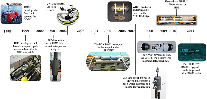
Figure 5. Timeline depicting the development of successful underwater mass spectrometer systems by various groups. Dates refer to the time of publication, not when the development commenced.
1TUHH, Technische Universität Hamburg-Harburg. Reprinted with permission from Matz and Kibelka (2001). Copyright 2001 Technische Universität Hamburg-Harburg (https://www.creativecommons.org/licenses/by-nc-sa/3.0/us/).
2, 3USF, University of South Florida. Photos courtesy of R.T. Short (SRI).
4MIT, Massachusetts Institute of Technology. Reprinted with permission from Camilli and Hemond (2004). Copyright 2004 Elsevier B.V.
5, 6UH SOEST, University of Hawaii School of Ocean and Earth Science and Technology. Photos courtesy of G.M. McMurtry (University of Hawaii).
7WHOI, Woods Hole Oceanographic Institution. Reprinted with permission from Camilli and Duryea (2007). Copyright 2007 MTS.
8SRI, SRI International. Reprinted with permission from Bell et al. (2007). Copyright 2007 American Chemical Society.
9AWI, Alfred Wegener Institute. Photo courtesy of M. Schlüter (AWI).
10MBARI, Monterey Bay Aquarium Research Institute. Photo courtesy of P. Girguis (Harvard University).
The initial emphasis of UMS deployments was on the detection and quantification of dissolved gases (e.g., O2, N2, and CH4,) and higher molecular weight VOCs (Table 4; Table S1). After the Deepwater Horizon incident in the Gulf of Mexico in 2010, which was the largest accidental marine oil spill in history, light hydrocarbons such as alkanes (including CH4) became prime targets. Nonetheless, quantification of dissolved gases remains important for marine science applications. The focus of the various research teams has largely been on the growth of UMS technology rather than on extensive field work, and so the total number of UMS deployments is still quite limited (Table S1). However, the rate of field applications and published reports appears to be increasing. This trend suggests that the engineering of UMS systems is progressing to the point to which such systems are becoming routinely useful as field instruments.
Below we present the successful UMS systems which have been developed. For each, we discuss the motivation behind their inception, an overview of their technical layout, and some of their applications to make measurements in the natural environment.
Gas Chromatography/Mass Spectrometry (GC/MS) System
The southeastern North Sea is heavily traversed by tankers and container ships containing large amounts of hazardous chemicals, and accidents may contaminate the marine environment (Matz and Kibelka, 2001). Chemicals with a low solubility in water and a higher density than water can form puddles on the sea floor and become long-term point sources, with adverse effects on fisheries and the environment. The detection of chemical pollutants via optical methods is more difficult than in the case of oil spills due to the chemicals' transparency, which is higher than that of oil (Gereit et al., 1998). To tackle this problem, scientists at the University of Hamburg-Harburg developed the membrane introduction GC/MS system with the goal of combating chemical pollution and clean-up operations (Gereit et al., 1998; Matz and Kibelka, 2001).
This system coupled the rapid separations achievable with a gas chromatograph with the detection capabilities of a mass spectrometer. At the heart of the system was a mobile mass spectrometer which was extremely heavy and consumed large amounts of power, and so was deployable via ROV but not AUV (Table 3). The sampling step of the GC/MS system took 3 min and commenced with an impellor pump sucking seawater through a heated membrane probe. VOCs permeated through the membrane while semi-volatile organic compounds (SVOCs) dissolved and were enriched in the membrane. A carrier gas stream carried volatile compounds into the transfer capillary. When sampling was finished, water was removed from the tubing system with nitrogen gas. Heating the membrane probe to 220°C caused the enriched SVOCs to thermally desorb and then be flushed onto the GC column by the carrier gas (Matz and Kibelka, 2001). Following sampling, GC/MS analysis took place. A complete analysis cycle, which included enrichment, desorption, injection, chromatography, and cleaning of the probe, took 7 min to complete (Matz and Kibelka, 2001). While the GC/MS system remains unmatched in analytical capability, its weight, power demands, and complexity, in particular with respect to in-water sampling, have limited further development of this technology.
The GC/MS system was test-deployed on a large ROV in the North Sea in a series of three cruises and successfully detected halogenated solvents. Further validation occurred aboard the “pollution control vessel” Mellum in the German Bight (Matz and Kibelka, 2001). Since 2000, the GC/MS system has been put to use by the Wasser- und Schifffahrtsamt (Waterways and Shipping Office), a regional German agency, to aid in clean-up missions of chemical dumping sites in the North and Baltic Seas (Table S1).
USF and SRI Systems
Scientists at the University of South Florida (USF) were among the first to acknowledge the trend toward automated or robotic sensing in the ocean. The main catalyst for unmanned operation was the harsh sampling and analysis environment posed by the ocean (Short et al., 1999). Another motivating factor was a desire for higher spatial and temporal resolution when collecting data, since traditional water-sample collection for laboratory analysis required the use of costly research vessels (both in terms of money and manpower), severely limiting sampling density.
The first version of the UMS system developed by Short, Fries, Byrne, and other colleagues at the USF was developed primarily to detect VOCs in water (Short et al., 1999). It used an Inficon Transpector quadrupole mass analyzer (100-amu mass range) interfaced with an unsupported PDMS capillary membrane of flow-through design. Peristaltic pumps introduced fixed volumes of preheated samples into the MIMS probe at low flow rates (Table 2). The system was initially tested in the laboratory to evaluate the instrument's detection limits of VOCs, with reproducibility of MIMS analyses typically better than 5% relative standard deviation (Table 4).
Over the next 8 years, the USF research group evaluated a number of technical developments to improve detection limits, power consumption and deployment range. The group experimented with an ion trap mass analyzer (Short et al., 2001; Fries et al., 2004), which had the advantage of lower detection limits for VOCs and an extended mass range (Table 3). Unfortunately, space-charge interferences from water vapor meant that compounds <40 amu (e.g., H2, O2, N2, CH4, and ethane) could not be resolved, limiting its applicability for many routine environmental analyses.
The performance characteristics of the USF linear quadrupole and ion trap systems were evaluated in a variety of shallow water, proof-of-concept field tests (Kibelka et al., 2004; Table S1). The quadrupole system was deployed in sewage influent, with all instrument subsystems functioning properly until the intake filter and membrane capillary clogged after 30 h. It was also used to investigate gases in a shallow (<30 m) submarine seep in the Gulf of Mexico, and the membrane interface was subsequently redesigned to allow for measurements at depths >200 m (Kibelka et al., 2004). The ion trap system was deployed in a marina in the Port of St. Petersburg and ran continuously for 72 h on a power tether. It monitored VOCs emitted by boats within the marina. Following this work, a suite of dissolved gases and VOCs in Bayboro Harbor (St. Petersburg, FL) and Lake Maggiore (St. Petersburg, FL) were measured and mapped with a 200-amu linear quadrupole system deployed on a remotely guided surface vehicle (Wenner et al., 2004). The instrument transmitted data via Ethernet link in real time to create high-resolution maps of chemical distributions in the saltwater and freshwater environments.
In 2007, researchers that transferred from USF to SRI International (SRI) continued developments and deployments of UMS systems. Since the Deepwater Horizon incident in 2010, a major focus of SRI's UMS development and deployments has been on the detection and mapping of light hydrocarbons (methane, ethane, propane, and butane) from natural hydrocarbon seeps and leaking oil and gas underwater assets (Short et al., 2011, 2013, 2015; Choyekh et al., 2015). The current generation of SRI instruments has a heated PDMS membrane supported by a sintered Hastelloy C rod (Bell et al., 2007), a more efficient linear quadrupole mass analyzer, and more compact vacuum pumps (Short et al., 2011, 2013, 2015). These improvements have doubled the range of masses that can be detected, increased the maximum operating depth to 2000 m, and decreased the power consumption by ~25% (Tables 3, 4).
As an initial test, the SRI UMS system was used to generate high-resolution, vertical profiles of dissolved gases in the Gulf of Mexico. Results showed good agreement between the UMS measurements and those obtained from a conventional CTD and oxygen sensor (Bell et al., 2007). In another mission, the UMS instrument was coupled to a sediment sampling probe and deployed on the Georgia continental shelf to measure dissolved gas profiles within sediment porewater (Bell et al., 2012; Table S1). This work constituted the first use of an underwater MIMS system to investigate dissolved gases in sediment porewater.
More recent efforts from the SRI group have focused on obtaining in situ measurements of total DIC and carbon (Bell et al., 2011; Cardenas-Valencia et al., 2013). DIC is a CO2 system variable which, along with alkalinity, controls seawater pH, carbonate saturation state, and CO2 fugacity. Presently rising atmospheric CO2 levels are leading to ocean acidification (Hennige et al., 2014). Increasing amounts of atmospheric CO2 are projected to decrease ocean pH by another 0.3–0.4 units by the end of the century as well as alter seawater carbonate chemistry (Caldeira and Wickett, 2003). This situation has stimulated much interest in tracking ocean DIC and carbon.
DIC can be measured by acidifying seawater to a pH below 3. At this value, virtually all DIC is present in the form of , where [] = [CO2] + [H2CO3] and [CO2]/[H2CO3] is ~850 over a wide range of temperatures (Soli and Byrne, 2002). , and hence DIC, can be measured using mass spectrometry. Bell et al. (2011) injected hydrochloric acid into their MIMS assembly via a syringe pump and found the MIMS response to be linearly dependent on DIC over a wide range of DIC concentrations. Ion current uncertainties were about 1% at m/z 44 (CO2) for an average DIC concentration of 2000 μmol. MIMS CO2 fugacity measurements were accurate to within 0.2% of certified reference standard values, but given that the standard deviation was 1.5%, the instrumental precision was too low for many carbon system measurements which require standard deviations lower than 1%. In order to eliminate the need for strong acids and associated mechanical pumps and reagent reservoirs in DIC measurements, Cardenas-Valencia et al. (2013) explored the feasibility of using in situ electrolysis to acidify samples during field measurements. Calibration curves obtained with this novel reagentless technique were similar to those obtained with the in-line strong acid addition technique. The electrolytic technique substantially reduced power requirements for in-line acidification, providing a further benefit during long-term deployments.
Cryotrap Membrane Inlet System (CT-MIS)
Much research on greenhouse gases in the aquatic environment is aimed at the detection and quantification of trace gases such as CO2, nitrous oxide (N2O), or DMS. Methane release from gassy sediments, hydrocarbon reserves, pipelines, or through dissociation of gas hydrates is also of interest since these spatially small discharge sites can be major drivers for the marine methane cycle. CH4 concentrations range from <4 nmol/L for surface waters of the open ocean to >1000 nmol/L in coastal regions or estuaries (e.g., Holmes et al., 2000; Middelburg et al., 2002). Although various techniques exist to localize discharge sites and analyze trace gases in aquatic environments, they do not permit high-resolution sampling and often introduce artifacts. In contrast, MIMS allows for the quantification of a multitude of gases within seconds.
A team at the Alfred Wegener Institute (AWI) for Polar and Marine Research decided to exploit the fast response time of MIMS by applying a UMS system (based on the USF quadrupole design) to map methane discharge sites in aquatic environments (Schlüter and Gentz, 2008). However, in initial field trials in the bottom waters of the Baltic Sea in which CO2 and O2 were successfully measured, no methane was detected by the UMS system (nor by a solid-state CH4 or optical CH4 sensor also included in the instrument package), suggesting that the CH4 concentrations were below the detection limits of all of the analyzers. Calibration of the UMS instrument revealed that its detection limit was >100 nmol/L, insufficient for detailed studies of CH4 concentrations. Schlüter and Gentz (2008) determined that the high background intensities observed were due to high amounts of water vapor (detected at m/z 18) permeating through the PDMS membrane, which were affecting the intensities detected at m/z 15 (methane). Thus, in order to enable lower detection limits they designed a novel “cool-trap” system.
The cool-trap consisted of a stainless steel capillary inserted into the vacuum section of the mass spectrometer, which was cooled down to −90°C to −80°C by liquid ethanol, in turn cooled down by liquid nitrogen or a thermostatic bath. The trap was cold enough to strip water vapor from the gas stream at pressures <10−5 Torr. The cool-trap reduced drift in the signals and minimized interferences caused by water vapor, lowering the detection limit of the UMS system to <16 nmol/L (Table 4) and enabling the investigation of CH4 concentrations in surface waters of coastal regions and lakes (Schlüter and Gentz, 2008). The cool-trap further served as a security system: in the event of a membrane rupture, the seawater flowing through the membrane capillary was instantly frozen within the cool-trap, preventing a complete flushing of the system with seawater.
Deployment of the cool-trap and UMS system occurred on board a research vessel in the Lake Constance (Schlüter and Gentz, 2008). Methane measurements revealed high spatial heterogeneity in the lake, with CH4 concentrations in surface water varying between 50 and 600 nmol/L within short distances. At a depth of 70 m, high CH4 concentrations of >1100 nmol/L were measured.
The same group later developed a Sterling pump-based cryotrap membrane inlet system, the CT-MIS (Gentz and Schlüter, 2012). Cryotraps applied in laboratories had successfully lessened interferences due to a high amount of water vapor entering the sensor system, and considerably improved the detection limits for e.g., VOCs, CH4, and DMS (Desmarais, 1978; Mendes et al., 1996; Damm et al., 2008). To adapt a cryotrap for use underwater, Gentz and Schlüter (2012) had to address the issues of size, waste-heat production, robustness, and energy consumption. The resulting CT-MIS was self-contained and could be coupled to different mass spectrometers. It operated at −85°C and trapped water vapor before it entered the analytical line, reducing water in the line by >98%. The mechanically robust cooling system was of low weight and size, produced modest amounts of waste heat, and had low power consumption (Table 3). Coupling the CT-MIS to a version of the USF quadrupole mass spectrometer allowed the system to measure CH4 concentrations down to 16 nmol/L, providing the ability for improved computation of mass budgets and enhanced localization of natural or anthropogenic point sources (Gentz and Schlüter, 2012).
The CT-MIS/UMS platform was deployed to investigate methane in the water column around gas seeps in the North Sea and to measure gas fluxes across the sediment-water interface in the Baltic Sea (Gentz and Schlüter, 2012; Table S1). This team used measurements made in situ around a pockmark to create a three-dimensional map of methane concentrations (Figure 6). Methane concentrations <100 nmol/L were observed for ~52% of the area surveyed. Consequently, without the application of the CT-MIS, methane would only have been detected within less than half of the study area. In another mission, Gentz et al. (2014) used the combined system to conduct a detailed study of methane seeps at the West Spitsbergen continental margin (Table S1). They found that during winter, the methane-enriched bottom water might potentially be an additional source of methane to the atmosphere.
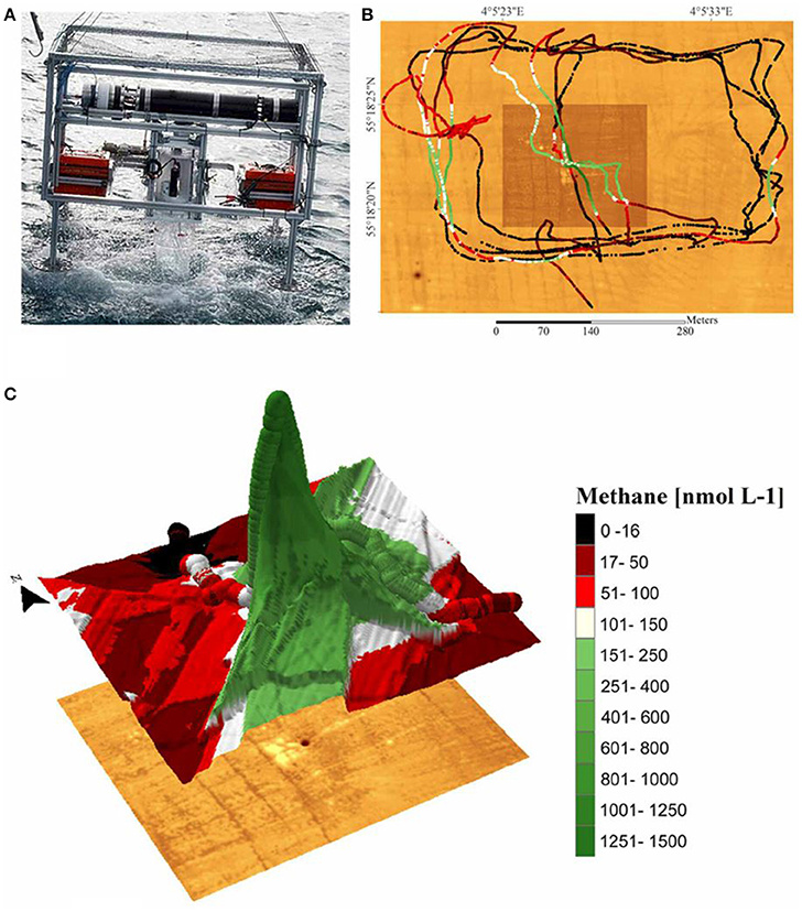
Figure 6. In situ methane measurements from hydrocarbon seeps associated with a pockmark structure (i.e., a crater in the seabed formed by the release of gases) in the North Sea. (A) Instrument frame on which the cryotrap membrane inlet system (CT-MIS) was coupled to the underwater mass spectrometer and deployed off a research vessel. (B) High resolution bathymetric map (brown underlay) and measured methane concentrations (colored lines). Before deployment, the bathymetry was derived by multibeam (a type of sonar system) survey and the pockmark was found to be <5 m in diameter. Subsequently, the CT-MIS was deployed at water depths of 10, 14, 24, and 34 m. When the deployment frame had reached its respective depth, the research vessel moved slowly around and across the site of gas seepage and gas concentrations were measured continuously every 1.8 s. The detection limit of the CT-MIS/underwater mass spectrometer for methane was 16 nmol/L. (C) Methane concentrations measured at 24 m water depth. Steep methane concentration gradients of >1200 nmol L−1 were detected close to the pockmark. Reprinted by permission from Gentz and Schlüter (2012), copyright 2012.
NEREUS and TETHYS
Engineers at MIT were also pioneers of the movement toward sensor development for exploration and analysis of the sub-surface aquatic environment. Motivated by the fact that the spatial and temporal resolution of conventional sampling devices, both ex situ (e.g., Weiss equilibrator) and in situ (e.g., O2 probes), is often lower than required to test hypotheses regarding environmental processes, Camilli and Hemond (2004) developed the UMS platform NEREUS. It was based on a back-packable, battery-powered mass spectrometer developed by Hemond (1991) and could be operated aboard an AUV, on a mooring, or on a winch line. NEREUS was unique as it used a cycloidal mass analyzer, whose double-focusing characteristic of crossed electric and magnetic fields allowed for a high mass resolution while maintaining a small physical size. It also had the lowest power needs of the UMS systems surveyed (Table 3), since the cycloidal mass analyzer used a fixed magnetic field maintained with a permanent magnet. A diode ion pump was used to maintain a high vacuum, instead of the usual high-power roughing pump-turbo pump combination, further lowering power consumption. A later version of NEREUS (Hemond et al., 2008) integrated safety features into the platform, including a solenoid valve which isolated the mass spectrometer in the event of a vacuum loss. In contrast to the cylindrical design of all of the other UMS systems surveyed, NEREUS was enclosed in a glass pressure sphere (Table 3).
During sampling, NEREUS was connected via a flexible stainless steel tube to an AUV, directly exposing the membrane inlet to the flow of water past the hull. The UMS system was tested in various laboratory and field settings including in a eutrophic urban lake during stratified conditions (Hemond et al., 2008). Dissolved gas profiles showed the expected features of a eutrophic stratified lake, and results were essentially in agreement with those obtained using a complementary set of chemical sensors attached to the AUV's hull.
Following the success of NEREUS, scientists at Woods Hole Oceanographic Institution (WHOI) and Monitor Instruments Co. developed the TETHYS mass spectrometer, whose design was partly based on its predecessor (Camilli and Duryea, 2007). This development was stimulated by a number of recent oil spills which had been hard to remediate due to inadequate sensing technology. While techniques existed to accurately identify oil spills through surface slick detection, state-of-the-art techniques for identifying subsurface contamination each had their limitations, and in general were slow, labor-intensive, and expensive (Camilli and Duryea, 2007). TETHYS was designed to fill this research niche and efficiently characterize hydrocarbons in subsurface marine environments.
The TETHYS system was optimized for endurance, depth, detection of low molecular weight chemicals, long-term accuracy, and overall reliability (Tables 3, 4). It was also rugged, compact, self-contained, and low-powered, and was deployable on a variety of platforms including moorings and AUVs (Tables 3, 4). Like NEREUS, it used a cycloidal mass analyzer. Unlike previous UMS systems, which used commercially-available quadrupole analyzers and pumping systems, TETHYS employed components designed specifically for underwater application. It had no moving parts, and thus was not affected by mechanical vibration. With detection limits of ~1 ppb and a ~5 s response time for light hydrocarbons, TETHYS enabled high spatial and temporal resolution measurements (Camilli and Duryea, 2007).
TETHYS has been deployed dozens of times on scientific expeditions since 2006 and is in routine use for offshore oil platform and pipeline leak and detection operations. For surveys of broad areas, TETHYS is typically set up in towfish configuration and towed along grid transects. Measurements gathered are used to construct geo-referenced maps of hydrocarbons. For smaller survey areas, slower-moving ROVs or submersibles act as the deployment vehicle, allowing for higher spatial resolution mapping of hydrocarbon sources near the seafloor or manmade structures. Using this approach, TETHYS has successfully located underwater broken pipelines and leaking oil platforms in the aftermath of hurricanes Katrina and Rita in the Gulf of Mexico (Camilli and Duryea, 2007; Table S1).
Perhaps the most famous example of a UMS system in action is the Deepwater Horizon oil spill response mission. During the June 2010 expedition, the TETHYS mass spectrometer was deployed on the Sentry AUV in order to survey and sample the oil plume (Table S1). Methane concentrations were measured in situ by TETHYS, and data revealed a continuous plume extending 30 km from the wellhead source and to a depth of 1100 m. Because TETHYS concurrently measured dissolved oxygen and argon as well as hydrocarbons, Camilli et al. (2010) were able to infer that the presence of elevated hydrocarbons was not associated with lowered oxygen concentrations, suggesting that hydrocarbons were not being significantly metabolized with the plume. Over two dives, Sentry spent 47.4 h deployed and covered over 170 km (Kinsey et al., 2011).
The most recent scientific mission of TETHYS involved surveying newly discovered shallow subsea pools in the South Aegean Sea, Greece, which accumulate CO2 emissions from sub-seafloor geologic reservoirs (Camilli et al., 2015; Figure 7; Table S1). The UMS system was used to analyze dissolved gases from pool fluid samples. Studying naturally-occurring seafloor pools such as these may help pinpoint potential volcanic activity, as well as aid in understanding CO2 leakage and benthic accumulations from subsea carbon capture and storage sites. Such work is crucial to understand the potential risks of storing CO2 within sub-seafloor geologic formations, which has emerged as a potential mechanism for reducing CO2 emissions and lessening the impacts of ocean acidification (Pires et al., 2011; Doelle and Lukaweski, 2012).
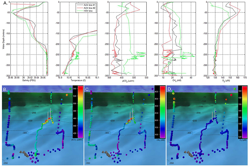
Figure 7. Water column profile data recorded by a TETHYS mass spectrometer during autonomous underwater vehicle (AUV) and human occupied submersible vehicle (HOV) survey operations. (A) Water column profiles of salinity, temperature, carbon dioxide partial pressure (pCO2), dissolved methane, and dissolved oxygen. Initial surveys were made during two AUV reconnaissance dives which indicated temperature, carbon dioxide, and methane anomalies between 230 and 270 m depth. Based on these signals, an HOV was deployed for closer inspection of the water column chemical anomalies. (B–D) Respectively, the pCO2, methane, and dissolved oxygen distributions recorded by the same AUV and HOV dives as in (A), but presented in geo-referenced format. Colored circles indicate dissolved chemical concentrations (color bar key located in upper right). Chemical measurements are shown as viewed from the Santorini caldera's North Basin, above the center of inflation, looking northeast toward the Kolumbo volcano. Gray pyramid-shaped icons indicate locations of hydrothermal vent mounds identified within the North Basin during prior ROV dive operations; white vertical lines indicate the uppermost and lowermost locations of the Kallisti Limnes CO2 subsea pools on the caldera wall. The dark blue color field with gray grid in the upper portion of (B–D) indicates the sea surface. Reprinted by permission from Camilli et al. (2015), copyright 2015 (http://creativecommons.org/licenses/by/4.0/).
Deep Ocean Mass Spectrometer (DOMS) and Mini-DOMS
Work by engineers at the University of Hawaii's School of Ocean and Earth Science and Technology (SOEST) was also motivated by the challenge of monitoring hydrocarbon seeps in the deep ocean (McMurtry et al., 2005). This is no easy task as seeps may be small, isolated, intermittent, and in hard-to-access areas. While seeps potentially represent a large source of gases and VOCs, they are poorly quantified (McMurtry et al., 2005). The SOEST team recognized that the development of a deep-sea instrument capable of prolonged deployments would greatly aid research requiring long-term monitoring of the environment.
McMurtry et al. (2005) designed and constructed an initial field prototype, the DOMS, which was based on a linear quadrupole mass analyzer. The ambitious goals of this group were to produce a platform that could operate for long periods of times (months to a year) with relatively low power consumption, while sampling at low-temperature (2–4°C) hydrothermal vents and cold seeps on the ocean floor (down to depths of 4000 m). To address the first two goals, it employed two modes of operation including a “sleep” mode, which reduced power needs and extended operation. In order to cope with the high pressures of the deep sea, the pressure housing was constructed of titanium alloys which are corrosion-proof over long-term deployments. Precautions against both fast and slow leaks were taken through the use of a valving system and a pressure-switch circuit/solenoid valve, respectively. The DOMS prototype was pressure-tested to 4000 m and survived a 4 month-long test deployment at 1000 m depth off the Costa Rica Pacific margin, a methane gas-rich cold seep area (McMurtry et al., 2011).
Recently, the University of Hawaii collaborated with Pace Tech and Brooks Automation to create the Mini-DOMS series, an improved version of the DOMS prototype (McMurtry et al., 2011, 2012). It has not yet been tested in the field. A key upgrade from the DOMS was the use of a new auto resonant ion trap (ART) mass analyzer. The ART analyzer allowed for a reduction in size and power (by 80%, down to 15 W) and an analysis speed that was 15 times faster, as well as improved vacuum systems. The new high vacuum system was based on a NEG ion pump assembly, whose lower power needs permitted longer-term sampling over traditional turbo pumps (Table 3; McMurtry et al., 2012). Currently under development is a heated, internal tubular membrane assembly which is claimed to improve sensitivity by 20-fold over present approaches (McMurtry et al., 2012). A suite of Mini-DOMS was successfully deployed in a 48-h pool test and field testing results are forthcoming.
In Situ Mass Spectrometer (ISMS)
The most recent published efforts to accurately measure methane concentration and flux using UMS came from researchers at Harvard University and the Monterey Bay Aquarium Research Institute (MBARI) (Wankel et al., 2010; Monterey Bay Aquarium Research Institute, 2016). Methane seeps and associated gas hydrates occur along many continental margins (Judd, 2003), and the destabilization of hydrates is sensitive to increases in temperature. Projected increases in mean global temperatures may trigger a release of methane into the ocean and atmosphere, potentially leading to a catastrophic greenhouse effect (Howarth, 2014). Due to limitations in methods and technology, it has been difficult to accurately constrain modern fluxes of methane from the deep sea into surface waters and eventually the atmosphere (Wankel et al., 2010).
The Harvard University and MBARI scientists developed a UMS system to better constrain biogeochemical fluxes and cycling and ultimately quantify the influence of biotic and abiotic processes on the methane cycle. The resulting ISMS consisted of three primary subsystems: a high pressure membrane inlet with a small-volume seawater pumping system, a linear quadrupole mass analyzer with an oil-less vacuum pumping system, and an underwater housing. A solenoid valve protected the mass spectrometer and pumps. Enclosing the power and communication channels in an underwater cable enabled real-time monitoring of chemical analytes during ROV operations, facilitating site selection and adaptive sampling.
The first mission for the ISMS involved a deployment on an ROV to make direct measurements of methane concentrations in a brine pool located in the Gulf of Mexico at a depth of over 2300 m (Wankel et al., 2010; Table S1). To sample the brine pool without disturbing the brine-seawater interface, the ISMS sample inlet was positioned and held in place by the ROV manipulator until the ISMS response reached steady state. These results allowed for the first accurate estimates of the diffusive flux from a brine pool with the overall finding that brine pools are considerable point sources of deep sea methane, which may have a significant impact on the global marine methane cycle (Wankel et al., 2010).
In a second mission, the ISMS measured CO2, CH4, and H2 from both diffuse and focused (high discharge) hydrothermal vents along the Juan de Fuca ridge (Wankel et al., 2011; Table S1). Prior geochemical vent studies had concentrated mostly on focused, high-temperature hydrothermal vents which are generally considered inhospitable for microbial life (Wankel et al., 2011). Relatively little is known about the extent to which microbial communities influence geochemical fluxes from cooler, more diffuse flows (Wankel et al., 2011). The Juan de Fuca deployment provided one of the first direct broad-scale constraints on the role of diffuse flows in the geochemical flux to the ocean. The ISMS was configured to sample vents in situ by using a titanium sampling wand connected via tubing to the membrane inlet. A submersible pumping system controlled the flow of sample water through the tubing. Results from these in situ measurements were used to create time-series of volatile (CO2, CH4, and H2) concentrations in the hydrothermal vent field (Figure 8). Total diffuse CH4 flux was approximately equal to the flux from focused flows, while CO2 fluxes were ~50% higher and H2 fluxes were ~50% lower from the diffuse flows. Wankel et al. (2011) attributed the loss of hydrogen to subsurface microbial consumption and, in light of this influence, concluded that geochemical flux from diffuse vents can actually exceed that emanating from hot, focused vents.
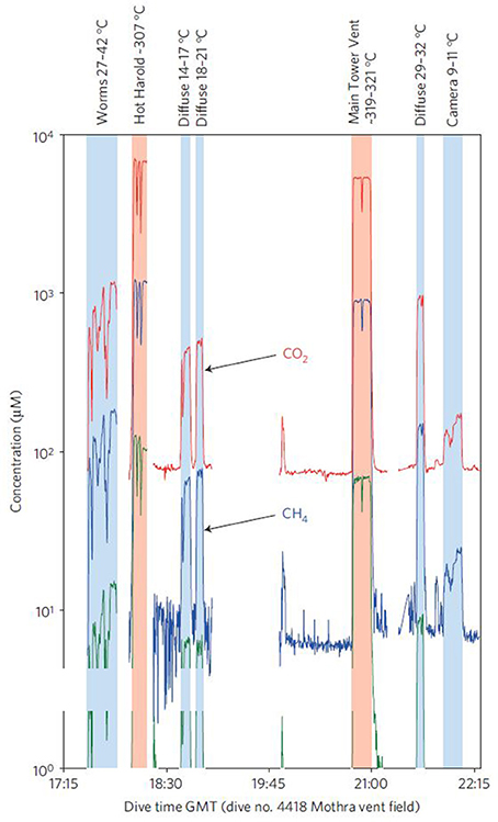
Figure 8. Time-series of selected volatile concentrations from a survey of the Faulty Towers vent structure in the Mothra hydrothermal vent field on the Juan de Fuca ridge as measured by the in situ mass spectrometer (ISMS) during a dive on 14 July 2008. Measurements were made by placing a sampling wand into environments and fluids of interest and continuously pumping sample fluids past the membrane inlet of the ISMS. ISMS ion intensities were related to concentrations by first correcting for small changes in inlet temperatures, and then converting the thermally-corrected signal intensities to analyte concentrations based on empirically-derived calibrations. The concentrations shown are for molecular H2 (m/z 2), CH4 (m/z 15), and CO2(aq) (m/z 44). For reference, the ambient sea water chemical composition is 31 μM CO2(aq), and 1 nM CH4 and H2. Reprinted by permission from Macmillan Publishers Ltd, (Wankel et al., 2011), copyright 2011.
Future Trends
Technological Innovations
A great deal of progress has been made in the field of UMS, but it has not yet reached its full potential. Two competing trends in terms of technological improvements are apparent. One is to simplify system components and reduce power needs. The other is to increase the complexity and sensitivity of measurements. Achieving these goals will greatly extend deployment endurance for routine monitoring missions, as well as allowing for specialized systems for sampling difficult environments (e.g., sediment porewaters, hydrothermal vent fluids, and seeps). Although, these goals are in direct conflict, both are desirable and their realization will require innovative solutions.
Technical improvements in hardware will simplify the instrument, leading to reduced power consumption and lower overall size. Lowering power consumption significantly below that of NEREUS is likely difficult as the hot filament used for sample ionization consumes almost half of the power budget (Hemond and Camilli, 2002). An alternative approach would be to use cold electron sources, which can operate at ambient temperatures and require less energy than other electron field emission methods. Miniaturizing UMS instruments further could lessen vacuum requirements, reducing power needs. Conceivably, such micro-UMS systems could be deployed for short periods of time and then retrieved (Busch, 2011).
Hardware development will also enable more sophisticated measurements including additional sensitivity, more rapid response time, and expanded mass range. Detection of additional trace analytes could extend pollution- or metabolite-sensing capabilities. Mass analyzers using an electron-multiplier detector as opposed to a Faraday cup detector may allow for higher sensitivities since the former provides a larger amount of nearly noise-free gain (i.e., MS signals are amplified, allowing for an increase in the signal-to-noise ratio; Hemond and Camilli, 2002). However, Faraday cups offer superior long-term gain stability (Camilli and Duryea, 2009) and better signal stability for UMS instruments on deployment platforms with significant vibration. Improved low-power vacuum pumps allow for increased analyte inflow and would also enhance sensitivity (Hemond and Camilli, 2002). Extending the mass range of mass analyzers by refining sample introduction and ionization methods would enable the detection of higher molecular weight (>200 amu) chemicals such as polychlorinated biphenyls (PCBs), which are environmentally-toxic pollutants. To accomplish this, sample introduction techniques other than membrane interfaces must be explored since in MIMS, the permeability of membranes to larger species becomes very low (Mills and Fones, 2012). In conventional MS, a number of ionization methods such as chemical ionization, desorption ionization, electrospray ionization (ESI), and ambient ionization are commonly used. The development of ESI was a particularly significant advance in the field of MS as it increased the molecular weight range by orders of magnitude, broadening the variety of compounds that can be ionized (Fenn, 2003). However, ESI has not yet been successfully integrated into UMS systems.
A new type of GC/MS instrument employing a miniature sector-field Mattauch-Herzog mass spectrometer (MHMS) is currently under development (Kibelka et al., 2011). This platform, the IonCam, couples an IonCCD ion detector array to the MHMS. The MHMS is double-focusing, offering enhanced mass resolving power. Initial experimental work found that the IonCCD can efficiently suppress artifacts related to secondary electron emission in the mass spectra observed by the MHMS (Hadjar et al., 2011). The IonCam system focuses ions of equal m/z simultaneously in a focal plane, allowing the observation of many chemical processes in real time. Analyzing these sequences of mass spectrometric frames as a “movie” provides insight into the dynamics of various processes (Kibelka et al., 2011). The IonCam has the potential to be packaged into an underwater system for applications in the ocean.
Recent work from Russell et al. (2016) focused on applying spatial coding techniques to magnetic sector MS in order to reduce the dichotomy between resolution and sensitivity inherent to MS. Although such techniques were proposed for use in MS in 1970 (Eckhardt and Gross, 1970), they have only recently been demonstrated (Chen et al., 2015; Russell et al., 2015). Specifically, these principles were applied to magnetic sector MS in order to minimize the losses in signal intensity which often accompany MS miniaturization efforts. Over 10 × increases in signal intensity were achieved, with no loss in mass resolution (Chen et al., 2015; Russell et al., 2015). Russell et al. (2016) demonstrated that spatially coded apertures are compatible with a MHMS, hinting at possible applications to the IonCam system.
Further exploratory analysis of membrane materials is required in order to improve the performance of underwater MIMS. A primary issue lies in resolving the confounding impacts of both temperature and pressure. While Bell et al. (2007) and Wankel et al. (2010) have conducted pressure calibrations for PDMS membranes over a limited depth range, it remains to be determined exactly how temperature and pressure interactions affect analyte diffusion across the various membrane types available (Moore et al., 2009). Recent studies have demonstrated that Teflon AF and PNC membranes show superior performance in some areas compared to PDMS (Miranda et al., 2011; Wankel et al., 2011). Future work should involve further investigating and exploiting these alternative materials via a comprehensive comparative analysis of their performance.
While conventional capillary hollow fiber membranes are well-suited for the analysis of non-polar analytes of low molecular weight (i.e., VOCs), MIMS analysis of semi-volatile compounds of higher molecular weight (i.e., SVOCs) is limited by relatively high detection limits and slow permeation of the compounds through the membrane (Thompson et al., 2006). For example, the detection limit for the SVOC guaiacol is typically >1 ppb with a response time of ≥20 min (Nelson et al., 2004). In comparison, the detection limit for the VOC toluene is two orders of magnitude lower with a response time of <1 min. Cyro-focusing (e.g., Bocchini et al., 2001) and thermally-assisted desorption (e.g., Riter et al., 2001) techniques have been used to enhance MIMS detection of these analytes. Cryo-focusing involves placing the membrane within a chemical trap (filled with an adsorbent), which is first cooled to concentrate the permeate in the trap and then heated to cause a rapid release of analytes. Similarly, thermally-assisted strategies involve externally heating the entire membrane interface to thermally desorb SVOCs from the membrane. The Applied Environmental Research Laboratories (AERL) group (Vancouver Island University, BC, Canada) developed and patented an internally heated MIMS interface for the rapid and sensitive on-line measurement of VOCs and SVOCs (Thompson et al., 2006; Krogh and Gill, 2009). This interface improved detection limits to pptr levels and shortened signal response times to 54–76 s for the environmentally-relevant SVOCs guaiacol, fluorine, biphenyl, trichloroanisole, and naphthalene, without compromising sensitivity for the representative VOC toluene (Thompson et al., 2006). Previous strategies that involved externally heating the entire membrane interface resulted in significant losses of analyte desorbed from the exterior of the membrane, since the outside of the membrane heated up first (Thompson et al., 2006). The AERL set-up involved an internal heater which consisted of a coaxial resistive heating wire passing through the center of a hollow fiber membrane. It heated the inner surface of the membrane before the outer surface, causing sample to preferentially desorb into the analyzer rather than into the waste stream. Applying a temperature gradient opposite to the analyte concentration gradient resulted in a greater mass transfer from the sample to the MS, with Thompson et al.'s (2006) system displaying typical sensitivities for SVOCs in water at the pptr level.
SRI has recently researched the implementation of Vancouver Island University's thermally-assisted MIMS interface (TAMI) technique into its own MIMS probe (Cardenas-Valencia, 2014). They successfully obtained mass spectra that showed that it may be possible to quantify polycyclic aromatic hydrocarbons (PAHS) in situ. This technique reduced the introduction time of the SVOCs naphthalene and pyrene into the vacuum system by ~60% and increased the detection sensitivity by 30–40%. While this work has so far been limited to bench top experiments, it demonstrates the feasibility of deploying the probe for the quantification of SVOCs.
Extending UMS analysis capabilities to detect non-volatile trace organics in seawater may become a reality with the development of underwater liquid chromatography/mass spectrometry (LC/MS). In LC/MS, a liquid chromatograph system is equipped with a mass spectrometer detector. This technique combines the physical separation of components using LC with the mass analysis capabilities of MS, and is used in many industrial fields. Although, MS can differentiate between many mixed chemicals on the basis of mass, chromatography is useful for two reasons. For one, many biologically-interesting chemicals exist as isomers, which have exactly the same mass and cannot be differentiated by a mass detector. Chromatography separates isomers before analysis. In addition, during the ionization process of a mixture of chemicals, ion suppression may occur in which the chemicals interact with each other and some may not be properly ionized. This affects the amount of charged ions reaching the detector from the suppressed chemical, reducing its signal. Pre-purifying the ionization mixture via chromatography mitigates this issue. Since LC provides limited information about the identity of a component, MS is subsequently used to quantify the masses of all the components present in a particular peak. Beckler et al. (2014) developed a technique coupling UV detection to anion chromatography to measure most seawater anions in a single step. This group is currently developing an underwater liquid chromatograph suitable for deployments on manned or unmanned underwater vehicles (e.g., submarines, gliders, and AUVs) for the in situ analysis of anions in marine water columns and sediment porewaters. Adapting this underwater liquid chromatograph for use with a mass spectrometer would extend UMS beyond its current limitation to dissolved gas and volatile organic analysis, representing a large step forward.
New Applications
As UMS becomes more widespread, so do its potential applications. An important limitation is that current UMS systems are not available for use by large groups of users. While a handful of systems capable of measuring different compounds in various environments have been developed, they are still individually custom-built. Current UMS instruments typically require a trained scientist to operate, so making systems more “turn-key” with automated start-up, operation, and calibration software would help to broaden their use significantly. Another large step forward would be to make UMS instruments mass-producible and thus more accessible for other research groups interested in making similar measurements. For example, designing systems so they can be readily constructed from off-the-shelf components would aid in dispersing UMS technology throughout the wider research community. This is the approach taken by our group, which is currently developing a novel in situ porewater sampler coupled to a UMS instrument for high-resolution gas measurements in permeable sands (http://www.fulweilerlab.com/porewater-mims-project.html).
In terms of future areas of development, several groups including ours and the ones who developed the Mini-DOMS (McMurtry et al., 2012) and the ISMS (Wankel et al., 2013) have stated their interest in producing in situ MIMS probes to make measurements within the porewaters of coastal marine sediments. Permeable sands cover around 70% of continental shelves (Emery, 1968) and recent studies have revealed them to be efficient filter systems which are important sites of biogeochemical activity, overturning the conventional view of these sands as “geochemical deserts” due to their low standing stocks of reactants and organic matter (Boudreau et al., 2001). There is a fundamental lack of understanding of critical biogeochemical processes on the continental shelf owing to a shortage of good data (Fennel et al., 2006), which is a casualty of the limitations of conventional sampling methodology. Using UMS to generate potentially long-duration and wide-coverage observations would provide important insights into biogeochemical cycling. Bell et al. (2012) have already developed a first generation porewater sampler which was deployed on the continental shelf in the South Atlantic Bight in 2008. Wankel et al. (2013) investigated the methane isotope content of porewater fluids by removing push cores and inserting a sample wand into the vacant hole. Future porewater sampling systems must be refined to operate in situ (with no core recovery), to not interfere with the advection field (by not having any enclosure artifacts), to have extended sampling endurance (in order to capture transient events), and to have the capacity to adaptively alter sampling regimes to accommodate changes in environmental forcing.
Real-time in situ isotopic analysis is another area of recent interest. The ability to measure in situ stable isotopes ratios would provide further insight into the processes driving fluxes (Wankel et al., 2013). Presently, isotope ratio mass spectrometry (IRMS) is the standard method for isotopic analyses in the laboratory. However, its associated infrastructure (e.g., a very high mass resolution instrument, or a pre-separation stage) has made its use in the field difficult. Some work in extending MIMS capabilities to isotope ratio measurements is emerging. The TETHYS instrument has already been used to produce time-series of stable isotope ratios in an embayment in Woods Hole, MA (Camilli and Duryea, 2009; Table S1). Over a 300-h deployment, TETHYS tracked fifteen m/z values to produce time-series of dissolved gas and isotope ratios, including N2 stable isotopes (14−15N2:14−14N2 at m/z 29:28) and CO2 stable isotopes (13CO2:12CO2 at m/z 45:44). These data revealed that N2 and CO2 isotope ratio periodicity occurred at an interval of exactly 24 h, suggesting that the solar diurnal periodicity is the factor controlling the gases' variability.
The desire to improve spatial and temporal coverage continues to drive progress. UMS technology has advanced to the point that instruments have been successfully deployed on tethered systems, human occupied submersibles, and underwater vehicles (Figure 1). A possible next step to extend sampling coverage would be to integrate UMS systems into existing sensor networks, such as the four Global Arrays implemented by the Ocean Observatories Initiative (OOI; http://oceanobservatories.org/). These vast networks of cabled arrays, moorings, profilers, AUVs, and gliders provide an integrated system to collect data on coastal, regional, and global scales. Given that the current number of UMS deployments is still quite limited (Table S1), coupling UMS instruments to this infrastructure would be a large push forward. A significant development occurred recently with the collaboration of the Girguis group at Harvard University and the OOI to deploy UMS systems off Washington and Oregon. One such UMS system has already been in operation for about a year at Hydrate Ridge, a gas hydrate ridge 100 km offshore of Oregon (Girguis, personal communication). Extending sampling coverage is also potentially feasible by installing porewater UMS systems on seafloor vehicles, such as MBARI's Benthic Rovers which creep along the ocean floor and can autonomously make measurements for months at a time (http://www3.mbari.org/news/news_releases/2009/rover/rover-release.html). Travelling UMS arrays would be able to sample vertically in the water column and in ocean sediments while covering large swaths of area horizontally. Similar to arrays of sensors that are already deployed globally, such as the thousands of Argo floats which profile the upper ocean, or the Tropical Atmosphere Ocean (TAO) moorings which are located throughout the entire tropical Pacific Ocean, arrays of mobile underwater mass spectrometers may conceivably populate the world's oceans in the near future.
Author Contributions
EC led the review and the design and development of the manuscript. RF helped design and coordinate the review. RF, TS, AC, and WS contributed to the development of the manuscript and provided feedback on all components of the manuscript. Note that all authors are participants in a collaborative project which led to the creation of this manuscript. Despite the fact that TS and AC are employed by SRI International, every effort has been made to objectively review UMS technology.
Conflict of Interest Statement
The authors declare that the research was conducted in the absence of any commercial or financial relationships that could be construed as a potential conflict of interest.
Acknowledgments
We gratefully acknowledge the National Science Foundation, which provided funding for this work through grants to RF (OCE-1435690), TS and AC (OCE-1436040), and WS (OCE-1435605) in Ocean Technology and Interdisciplinary Coordination. We are also thankful to Boston University, Fulbright Canada, and the Natural Sciences and Engineering Research Council of Canada, who provided additional funding to EC. We greatly appreciate the help of Gottfried Kibelka for supplying difficult-to-find information and for his words of advice.
Supplementary Material
The Supplementary Material for this article can be found online at: https://www.frontiersin.org/article/10.3389/fmars.2016.00209/full#supplementary-material
Abbreviations
ART, autoresonant ion trap; AUV, autonomous underwater vehicle; CTD, conductivity, temperature, depth; DC, direct current; DIC, dissolved inorganic carbon; GC/MS, gas chromatography/mass spectrometry; IRMS, isotope ratio mass spectrometry; ISMS, in situ mass spectrometer; LC/MS, liquid chromatography/mass spectrometry; MHMS, Mattauch-Herzog mass spectrometer; MIMS, membrane inlet mass spectrometry; MS, mass spectrometry; m/z, mass-to-charge ratio; NEG, non-evaporable getter; NCP, net community production; PDMS, polydimethylsiloxane; RF, radio frequency; ROV, remotely-operated vehicle; SVOC, semi-volatile organic compound; TAMI, thermally-assisted MIMS interface; UMS, underwater mass spectrometry; VOC, volatile organic compound.
References
Atkinson, M. J., Thomas, F. I. M., Larson, N., Terrill, E., Morita, K., and Liu, C. C. (1995). A microhole potentionstatic oxygen sensor for oceanic CTDs. Deep-Sea Res. Part I -Oceanogr. Res. Pap. 42, 761–771. doi: 10.1016/0967-0637(95)00019-3
Badman, E. R., and Cooks, R. G. (2000). Miniature mass analyzers. J. Mass Spectrom. 35, 659–671. doi: 10.1002/1096-9888(200006)35:6<659::AID-JMS5>3.0.CO;2-V
Baumgärtl, H., and Lübbers, D. W. (1973). “Platinum needle electrodes for polarographic measurement of oxygen and hydrogen,” in Oxygen Supply, eds M. Kessler, D. F. Bruley, L. C. Clark, D. W. Lübbers, A. Silver, and J. Sträuss (Munchen: Urban and Schwarzenberg), 130–136.
Beckler, J. S., Nuzzio, D. B., and Taillefert, M. (2014). Development of single-step liquid chromatography methods with ultraviolet detection for the measurement of inorganic anions in marine waters. Limnol. Oceanogr. Methods 12, 563–576. doi: 10.4319/lom.2014.12.563
Bell, R. J., Savidge, W. B., Toler, S. K., Byrne, R. H., and Short, R. T. (2012). In situ determination of porewater gases by underwater flow-through membrane inlet mass spectrometry. Limnol. Oceanogr. Methods 10, 117–128. doi: 10.4319/lom.2012.10.117
Bell, R. J., Short, R. T., and Byrne, R. H. (2011). In situ determination of total dissolved inorganic carbon by underwater membrane introduction mass spectrometry. Limnol. Oceanogr. Methods 9, 164–175. doi: 10.4319/lom.2011.9.164
Bell, R. J., Short, R. T., Van Amerom, F. H. W., and Byrne, R. H. (2007). Calibration of an in situ membrane inlet mass spectrometer for measurements of dissolved gases and volatile organics in seawater. Environ. Sci. Technol. 41, 8123–8128. doi: 10.1021/es070905d
Bocchini, P., Pozzi, R., Andalo, C., and Galletti, G. C. (2001). Experimental upgrades of membrane introduction mass spectrometry for water and air analysis. Anal. Chem. 73, 3824–3827. doi: 10.1021/ac010249e
Boudreau, B. P., Huettel, M., Forster, S., Jahnke, R. A., McLachlan, A., Middelburg, J. J., et al. (2001). Permeable marine sediments: overturning an old paradigm. EOS 82, 135–136. doi: 10.1029/EO082i011p00133-01
Boulart, C., Connelly, D. P., and Mowlem, M. C. (2010). Sensors and technologies for in situ dissolved methane measurements and their evaluation using Technology Readiness Levels. Trends Anal. Chem. 29, 186–195. doi: 10.1016/j.trac.2009.12.001
Boulart, C., Prien, R., Chavagnac, V., and Dutasta, J. P. (2013). Sensing dissolved methane in aquatic environments: an experiment in the central Baltic Sea using surface plasmon resonance. Environ. Sci. Technol. 47, 8582–8590. doi: 10.1021/es4011916
Brewer, P. G., Malby, G., Pasteris, J. D., White, S. N., Peltzer, E. T., Wopenka, B., et al. (2004). Development of a laser Raman spectrometer for deep-ocean science. Deep-Sea Res. Part I-Oceanogr. Res. Pap. 51, 739–753. doi: 10.1016/j.dsr.2003.11.005
Caldeira, K., and Wickett, M. E. (2003). Anthropogenic carbon and ocean pH. Nature 425:365. doi: 10.1038/425365a
Camilli, R., and Duryea, A. (2007). Characterizing marine hydrocarbons with in-situ mass spectrometry. Proc. MTS/IEEE Oceans 2007, 1–7. doi: 10.1109/oceans.2007.4449412
Camilli, R., and Duryea, A. (2009). Characterizing spatial and temporal variability of dissolved gases in aquatic environments with in situ mass spectrometry. Environ. Sci. Technol. 43, 5014–5021. doi: 10.1021/es803717d
Camilli, R., and Hemond, H. F. (2004). NEREUS/Kemonaut, a mobile autonomous underwater mass spectrometer. Trends Anal. Chem. 23, 307–313. doi: 10.1016/S0165-9936(04)00408-X
Camilli, R., Nomikou, P., Escartin, J., Ridao, P., Mallios, A., Kilias, S. P., et al. (2015). The Kallisti Limnes, carbon-dioxide accumulating subsea pools. Sci. Rep. 5. doi: 10.1038/srep12152
Camilli, R., Reddy, C. M., Yoerger, D. R., Van Mooy, B. A. S., Jakuba, M. V., Kinsey, J. C., et al. (2010). Tracking hydrocarbon plume transport and biodegradation at Deepwater Horizon. Science 330, 201–204. doi: 10.1126/science.1195223
Cardenas-Valencia, A. M. (2014). “Underwater mass spectrometer,” in Presentation at the Fifth International Dialogue on Underwater Munitions (Halifax, NS). Available online at: http://www.underwatermunitions.org/pdf/DRAFT_AGENDA_5TH%20IDUM.pdf
Cardenas-Valencia, A. M., Adornato, L. R., Bell, R. J., Byrne, R. H., and Short, R. T. (2013). Evaluation of reagentless pH modification for in situ ocean analysis: determination of dissolved inorganic carbon using mass spectrometry. Rapid Commun. Mass Spectrom. 27, 635–642. doi: 10.1002/rcm.6487
Chen, E. X., Russell, Z. E., Amsden, J. J., Wolter, S. D., Danell, R. M., Parker, C. B., et al. (2015). Order of magnitude signal gain in magnetic sector mass spectrometry via aperture coding. J. Am. Soc. Mass Spectrom. 26, 1633–1640. doi: 10.1007/s13361-015-1178-y
Choyekh, M., Kato, N., Short, T., Ukita, M., Yamaguchi, Y., Senga, H., et al. (2015). Vertical water column survey in the Gulf of Mexico using autonomous underwater vehicle SOTAB-I. Mar. Technol. Soc. J. 49, 88–101. doi: 10.4031/MTSJ.49.3.8
Damm, E., Kiene, R. P., Schwarz, J., Falck, E., and Dieckmann, G. (2008). Methane cycling in Arctic shelf water and its relationship with phytoplankton biomass and DMSP. Mar. Chem. 109, 45–59. doi: 10.1016/j.marchem.2007.12.003
de Beer, D., Glud, A., Epping, E., and Kuhl, M. (1997). A fast-responding CO2 microelectrode for profiling sediments, microbial mats, and biofilms. Limnol. Oceanogr. 42, 1590–1600. doi: 10.4319/lo.1997.42.7.1590
DeGrandpre, M. D., Hammar, T. R., Smith, S. P., and Sayles, F. L. (1995). In-situ measurements of seawater pCO2. Limnol. Oceanogr. 40, 969–975. doi: 10.4319/lo.1995.40.5.0969
Desmarais, D. J. (1978). Variable-temperature cryogenic trap for separation of gas-mixtures. Anal. Chem. 50, 1405–1406. doi: 10.1021/ac50031a056
Doelle, M., and Lukaweski, E. (2012). Carbon capture and storage in the CDM: finding its place among climate mitigation options? Clim. Law 3, 49–69. doi: 10.3233/CL-2012-056
Dullo, F., Lindecrantz, S., Jágerská, J., and Hellesø, O. G. (2015). Sensitive on-chip methane detection with a cryptophane-A cladded Mach-Zehnder interferometer. Opt. Express 23, 31564–31573. doi: 10.1364/OE.23.031564
Eckhardt, C. J., and Gross, M. L. (1970). A proposed technique for signal multiplexing in mass spectrometry. Int. J. Mass Spectrom. Ion Phys. 5, 223–227. doi: 10.1016/0020-7381(70)80017-1
Emery, K. O. (1968). Relict sediments on continental shelves of the world. Am. Assoc. Petrol. Geol. 52, 445–464.
Fenn, J. B. (2003). Electrospray wings for molecular elephants (Nobel Lecture). Angew. Chem. Int. Ed. Engl. 42, 38–71. doi: 10.1002/anie.200300605
Fennel, K., Wilkin, J., Levin, J., Moisan, J., O'reilly, J., and Haidvogel, D. (2006). Nitrogen cycling in the Middle Atlantic Bight: results from a three-dimensional model and implications for the North Atlantic nitrogen budget. Global Biogeochem. Cycles 20. doi: 10.1029/2005GB002456
Fries, D. P., Short, R. T., and Byrne, R. H. (2004). Portable Underwater Mass Spectrometer. U.S. Patent Publication No. US6727498 B2.
Fujita, H. (1961). Diffusion in polymer-diluent systems. Algebra Univ. 3, 1–47. doi: 10.1007/bfb0050514
Garcia, H. E., and Gordon, L. I. (1992). Oxygen solubility in seawater: better fitting equations. Limnol. Oceanogr. 37, 1307–1312. doi: 10.4319/lo.1992.37.6.1307
Gentz, T., Damm, E., Schneider von Deimling, J., Mau, S., McGinnis, D. F., and Schlüter, M. (2014). A water column study of methane around gas flares located at the West Spitsbergen continental margin. Cont. Shelf. Res. 72, 107–118. doi: 10.1016/j.csr.2013.07.013
Gentz, T., and Schlüter, M. (2012). Underwater cryotrap-membrane inlet system (CT- MIS) for improved in situ analysis of gases. Limnol. Oceanogr. Methods 10, 317–328. doi: 10.4319/lom.2012.10.317
Gereit, F., Hauptmann, P., Matz, G., Mellert, V., and Reuter, R. (1998). An ROV-based sensor system for maritime pollution control. Oceanol. Int. 98 55–69.
Hadjar, O., Schlathölter, T., Davila, S., Catledge, S. A., Kuhn, K., Kassan, S., et al. (2011). IonCCD detector for miniature sector-field mass spectrometer: investigation of peak shape and detector surface artifacts induced by keV ion detection. J. Am. Soc. Mass Spectrom. 22, 1872–1884. doi: 10.1007/s13361-011-0213-x
Hamme, R. C., and Emerson, S. R. (2004). The solubility of neon, nitrogen and argon in distilled water and seawater. Deep Sea Res. Part I 51, 1517–1528. doi: 10.1016/j.dsr.2004.06.009
Hemond, H. (1991). A backpack-portable mass spectrometer for measurement of volatile compounds in the environment. Rev. Sci. Instrum. 62, 1420–1425. doi: 10.1063/1.1142461
Hemond, H., and Camilli, R. (2002). NEREUS: engineering concept for an underwater mass spectrometer. Trends Anal. Chem. 21, 526–533. doi: 10.1016/S0165-9936(02)00113-9
Hemond, H. F., Mueller, A. V., and Hemond, M. (2008). Field testing of lake water chemistry with a portable and an AUV-based mass spectrometer. J. Am. Soc. Mass Spectrom. 19, 1403–1410. doi: 10.1016/j.jasms.2008.04.019
Hennige, S. J., Wicks, L. C., Kamenos, N. A., Bakker, D. C. E., Findlay, H. S., Dumousseaud, C., et al. (2014). Short-term metabolic and growth responses of the cold-water coral Lophelia pertusa to ocean acidification. Deep Sea Res. Part II Top. Stud. Oceanogr. 99, 27–35. doi: 10.1016/j.dsr2.2013.07.005
Hoch, G., and Kok, B. (1963). A mass spectrometer inlet system for sampling gases dissolved in liquid phases. Arch. Biochem. Biophys. 101, 160–170. doi: 10.1016/0003-9861(63)90546-0
Holmes, M. F., Sansone Rust, T., and Popp, P. (2000). Methane production, consumption, and air-sea exchange in the open ocean: an evaluation based on carbon isotopic ratios. Global Biogeochem. Cycles 14, 1–10. doi: 10.1029/1999GB001209
Howarth, R. W. (2014). A bridge to nowhere: methane emissions and the greenhouse gas footprint of natural gas. Energy Sci. Eng. 2, 47–60. doi: 10.1002/ese3.35
Huettel, M., Berg, P., and Kostka, J. E. (2014). Benthic exchange and biogeochemical cycling in permeable sediments. Annu. Rev. Mar. Sci. 6, 23–51. doi: 10.1146/annurev-marine-051413-012706
Janfelt, C., Lauritsen, F. R., Toler, S. K., Bell, R. J., and Short, R. T. (2007). Method for quantification of chemicals in a pollution plume using a moving membrane-based sensor exemplified by mass spectrometry. Anal. Chem. 79, 5336–5342. doi: 10.1021/ac070408f
Johnson, K. S., Beehler, C. L., Sakamotoarnold, C. M., and Childress, J. J. (1986). In situ measurements of chemical distributions in a deep-sea hydrothermal vent field. Science 231, 1139–1141. doi: 10.1126/science.231.4742.1139
Johnson, K. S., Coale, K. H., and Jannasch, H. W. (1992). Analytical chemistry in oceanography. Am. Chem. Soc. 64, 1065–1075.
Johnson, R. C., Cooks, R. G., Allen, T. M., Cisper, M. E., and Hemberger, P. H. (2000). Membrane introduction mass spectrometry: trends and applications. Mass Spec. Rev. 19, 1–37. doi: 10.1002/(SICI)1098-2787(2000)19:1<1::AID-MAS1>3.0.CO;2-Y
Judd, A. G. (2003). The global importance and context of methane escape from the seabed. Geo-Mar. Lett. 23, 147–154. doi: 10.1007/s00367-003-0136-z
Kaiser, J., Reuer, M. K., Barnett, B., and Bender, B. L. (2005). Marine productivity estimates from continuous O2/Ar ratio measurements by membrane inlet mass spectrometry. Geophys. Res. Lett. 32, L19605. doi: 10.1029/2005GL023459
Kibelka, G. P. G., Hadjar, O., Kassan, S., and Cameron, C. (2011). “Transportable sector-field MS with ion detector array,” in Poster Session Presented at 8th Workshop on Harsh-Environment Mass Spectrometry (St. Pete Beach, FL).
Kibelka, G. P. G., Short, R. T., Toler, S. K., Edkins, J. E., and Byrne, R. H. (2004). Field-deployed underwater mass spectrometers for investigations of transient chemical systems. Talanta 64, 961–969. doi: 10.1016/j.talanta.2004.04.028
Kinsey, J. C., Yoerger, D. R., Jakuba, M. V., Camilli, R., Fisher, C. R., and German, C. R. (2011). “Assessing the deepwater horizon oil spill with the Sentry autonomous underwater vehicle,” in Proceedings of the 2011 IEEE/RSJ International Conference on Intelligent Robots and Systems (IROS) (San Francisco, CA), 261–267.
Kraft, M., Jakusch, M., Karlowatz, M., Katzir, A., and Mizaikoff, B. (2003). New frontiers for mid-infrared sensors: towards deep sea monitoring with a submarine FT-IR sensor system. Appl. Spectrosc. 57, 591–599. doi: 10.1366/000370203322005256
Kraker, E., Haase, A., Lamprecht, B., Jakopic, G., Konrad, C., and Kostler, S. (2008). Integrated organic electronic based optochemical sensors using polarization filters. Appl. Phys. Lett. 92, 033302. doi: 10.1063/1.2837410
Krogh, E. T., and Gill, C. G. (2009). Thermally Assisted Membrane Introduction Mass Spectrometry (MIMS) Interface and Method of Use Thereof. U.S. Patent Publication No. US-2007-0181799-A1.
Lamontagne, R. A., Rose-Pehrsson, S. L., Grabowski, K. E., and Knies, D. L. (2001). Response of METS Sensor to Methane Concentrations Found on the Texas-Louisiana Shelf in the Gulf of Mexico. Naval Research Laboratory Memorandum Report NRL-MR-6110–01-8584, Washington, DC.
LaPack, M. A., Tou, J. C., and Enke, C. G. (1990). Membrane mass spectrometry for the direct trace analysis of volatile organic compounds in air and water. Anal. Chem. 62, 1265–1271. doi: 10.1021/ac00212a013
Lawrence, N. S. (2006). Analytical detection methodologies for methane and related hydrocarbons. Talanta 69, 385–392. doi: 10.1016/j.talanta.2005.10.005
Le Bris, N., Sarradin, P. M., Birot, D., and Alayse-Danet, A. M. (2000). A new chemical analyzer for in situ measurement of nitrate and total sulfide over hydrothermal vent biological communities. Mar. Chem. 72, 1–15. doi: 10.1016/S0304-4203(00)00057-8
Liebsch, G., Klimant, I., Frank, B., Holst, G., and Wolfbeis, O. S. (2000). Luminescence lifetime imaging of oxygen, pH, and carbon dioxide distribution using optical sensors. Appl. Spectrosc. 54, 548–559. doi: 10.1366/0003702001949726
Lindecrantz, S. M. (2016). Waveguide Mach-Zehnder Interferometer for Measurement of Methane Dissolved in Water. Dissertation/Doctoral thesis, University of Tromsø, Tromsø.
Maher, S., Jjunju, F. P. M., and Taylor, S. (2015). Colloquium: 100 years of mass spectrometry: perspectives and future trends. Rev. Mod. Phys. 87, 113–135. doi: 10.1103/RevModPhys.87.113
Martini, M., Butman, B., and Mickelson, M. J. (2007). Long-term performance of Aanderaa optodes and Sea-Bird SBE-43 dissolved-oxygen sensors bottom mounted at 32 m in Massachusetts Bay. J. Atmos. Ocean. Technol. 24, 1924–1935. doi: 10.1175/JTECH2078.1
Matz, G., and Kibelka, G. (2001). Detection of Chemicals in the Sea. Hannover: Hamburg-Harburg Arbeitsbereich Meßtechnik, Techn. Univ.
McMurtry, G., Kolotyrkina, I. Y., Brucker, G., and Rathbone, J. (2011). “New generation underwater mass spectrometers for dissolved gases and volatile organic compound detection and in situ monitoring in the oceans,” in Proc. MTS/IEEE Oceans (Kona) 11, 1–4.
McMurtry, G., Kolotyrkina, I. Y., Lee, J. S., and Kim, K. H. (2012). “Underwater mass spectrometers for in situ monitoring of dissolved gases and volatile organic compounds in deep ocean and coastal environments,” in Proc. MTS/IEEE Oceans 2012 (Virginia Beach, VA), 1–6.
McMurtry, G., Wiltshire, J. C., and Bossuyt, A. (2005). “Hydrocarbon seep monitoring using in situ deep sea mass spectrometry,” in Oceans 2005 - Europe (Brest), 1, 395–400.
Mendes, M. A., Pimpim, R. S., Kotiaho, T., Barone, J. S., and Eberlin, M. N. (1996). The construction of a membrane probe and its application towards the analysis of volatile organic compounds in water via the MIMS and MIMS/MS techniques. Quim Nova 19, 480–485.
Middelburg, J. J., Nieuwhenhuize, J., Iversen, N., Hogh, N., DeWilde, H., Helder, W., et al. (2002). Methane distribution in European tidal estuaries. Biogeochemistry 59, 95–119. doi: 10.1023/A:1015515130419
Mills, G., and Fones, G. (2012). A review of in situ methods and sensors for monitoring the marine environment. Sensor Rev. 32, 17–28. doi: 10.1108/02602281211197116
Miranda, L. D., Bell, R. J., Short, R. T., van Amerom, F. H. W., and Byrne, R. H. (2011). The influence of hydrostatic pressure on gas diffusion in polymer and nano-composite membranes: application to membrane inlet mass spectrometry J. Membr. Sci. 385, 49–56. doi: 10.1016/j.memsci.2011.09.009
Monterey Bay Aquarium Research Institute (2016). New Robot Travels Across the Seafloor to Monitor the Impact of Climate Change on Deep-Sea Ecosystems. Available online at: http://www3.mbari.org/news/news_releases/2009/rover/rover-release.html (Accessed January 19, 2016).
Moore, T. S., Mullaugh, K. M., Holyoke, R. R., Madison, A. S., Yücel, M., and Luther, G. W. III. (2009). Marine chemical technology and sensors for marine waters: potentials and limits. Annu. Rev. Mar. Sci. 1, 19–115. doi: 10.1146/annurev.marine.010908.163817
Nelson, J. H. L., Thompson, A. J., Friesen, D. A., Krogh, E. T., Dills, R. L., Simpson, C. D., et al. (2004). “Real-time monitoring of urban air for wood-smoke and vehicle emission tracer molecules by membrane introduction tandem mass spectrometry (MIMS-MS/MS),” in 52nd American Society for Mass Spectrometry Conference (Nashville, TN).
Ouyang, Z., and Cooks, R. G. (2009). Miniature mass spectrometers. Annu. Rev. Anal. Chem 2, 187–214. doi: 10.1146/annurev-anchem-060908-155229
Pinnau, I., and Toy, L. G. (1996). Gas and vapor transport properties of amorphous perfluorinated copolymer membranes based on 2,2-bistrifluoromethyl-4,5-difluoro-1,3-dioxole/tetrafluoroethylene. J. Membr. Sci. 109, 125–133. doi: 10.1016/0376-7388(95)00193-X
Pires, J., Martins, F., Alvim-Ferraz, M., and Simoes, M. (2011). Recent developments on carbon capture and storage: an overview. Chem. Eng. Res. Des. 89, 1446–1460. doi: 10.1016/j.cherd.2011.01.028
Revsbech, N. P., Nielsen, L. P., Christensen, P. B., and Sorensen, J. (1988). Combined oxygen and nitrous-oxide microsensor for denitrification studies. Appl. Environ. Microbiol. 54, 2245–2249.
Revsbech, N. P., and Ward, D. M. (1983). Oxygen microelectrode that is insensitive to medium chemical-composition—use in an acid microbial mat dominated by cyanidium-caldarium. Appl. Environ. Microbiol. 45, 755–759.
Riter, L. S., Takáts, Z., Charles, L., and Cooks, R. G. (2001). High surface area membrane introduction mass spectrometry for analysis of volatile and semi-volatile organic compounds in air. Rapid Commun. Mass Spectrom. 15, 1520–1524. doi: 10.1002/rcm.401
Russell, Z. E., Chen, E. X., Amsden, J. J., Wolter, S. D., Danell, R. M., Parker, C. B., et al. (2015). Two-dimensional aperture coding for magnetic sector mass spectrometry. J. Am. Soc. Mass Spectrom. 26, 248–256. doi: 10.1007/s13361-014-1051-4
Russell, Z. E., DiDona, S. T., Amsden, J. J., Parker, C. B., Kibelka, G., Gehm, M. E., et al. (2016). Compatibility of spatially coded apertures with a miniature Mattauch-Herzog mass spectrograph. J. Am. Soc. Mass Spectrom. 27, 578–584. doi: 10.1007/s13361-015-1323-7
Schlüter, M., and Gentz, T. (2008). Application of membrane inlet mass spectrometry for online and in situ analysis of methane in aquatic environments. J. Am. Soc. Mass. Spectrom. 19, 1395–1402. doi: 10.1016/j.jasms.2008.07.021
Schroeder, C. R., Neurauter, G., and Klimant, I. (2007). Luminescent dual sensor for time-resolved imaging of pCO2 and pO2 in aquatic systems. Microchim. Acta 158, 205–218. doi: 10.1007/s00604-006-0696-5
Short, R. T., Fries, D. P., Kerr, M. L., Lembke, C. E., Toler, S. K., Wenner, P. G., et al. (2001). Underwater mass spectrometers for in-situ chemical analysis of the hydrosphere. J. Am. Soc. Mass Spectrom. 12, 676–682. doi: 10.1016/S1044-0305(01)00246-X
Short, R. T., Fries, D. P., Koler, S. K., Lembke, C. E., and Byrne, R. H. (1999). Development of an underwater mass-spectrometry system for in situ chemical analysis. Meas. Sci. Technol. 10, 1195–1201. doi: 10.1088/0957-0233/10/12/311
Short, R. T., Toler, S. K., Bell, R. J., and Byrne, R. H. (2011). “Underwater membrane introduction mass spectrometers: recent developments and deployments,” in Presentation at the 8th HEMS Workshop (St. Pete Beach, FL). Available online at: http://www.hems-workshop.org/8thWS/Presentations/Tuesday/3_Short.pdf
Short, R. T., Toler, S. K., Bell, R. J., Cardenas-Valencia, A. M., Dholakia, J., and Untiedt, S. (2013). “In situ membrane introduction mass spectrometry for subsea characterization of light hydrocarbons,” in Presentation at the 9th HEMS Workshop (St. Pete Beach, FL), 15–18. Available online at: http://www.hems-workshop.org/9thWS/Presentations/Short.pdf
Short, R. T., Toler, S. K., Cardenas-Valencia, A. M., Untiedt, S., Cullins, C., Ryder, M., et al (2015). “In-water mass spectrometry for characterization of light hydrocarbon seeps and leaks,” in Presentation at the 10th HEMS Workshop (Baltimore, MD), 13–16. Available online at: http://www.hems-workshop.org/10thWS/Talks/Short.pdf
Short, R. T., Toler, S. K., Kibelka, G. P. G., Rueda Roa, D. T., Bell, R. J., and Byrne, R. H. (2006). Detection and quantification of chemical plumes using a portable underwater membrane introduction mass spectrometer. Trends Anal. Chem. 25, 637–646 doi: 10.1016/j.trac.2006.05.002
Snyder, D. T., Pulliam, C. J., Ouyang, Z., and Cooks, R. J. (2015). Miniature and fieldable mass spectrometers: recent advances. Anal. Chem. 88, 2–29. doi: 10.1021/acs.analchem.5b03070
Soli, A. L., and Byrne, R. H. (2002). CO2 system hydration and dehydration kinetics and the equilibrium CO2/H2CO3 ratio in aqueous NaCl solution. Mar. Chem. 78, 65–73. doi: 10.1016/S0304-4203(02)00010-5
Tengberg, A., Hovdenes, J., Andersson, H. J., Brocandel, O., Diaz, R., Hebert, D., et al. (2006). Evaluation of a lifetime-based optode to measure oxygen in aquatic systems. Limnol. Oceanogr. Methods 4, 7–17. doi: 10.4319/lom.2006.4.7
Thompson, A. J., Creba, A. S., Ferguson, R. M., Krogh, E. T., and Gill, C. G. (2006). A coaxially heated membrane introduction mass spectrometry interface for the rapid and sensitive on-line measurement of volatile and semi-volatile organic contaminants in air and water at parts-per-trillion levels. Rapid Commun. Mass Spectrom. 20, 2000–2008. doi: 10.1002/rcm.2551
Tortell, P. D. (2005). Dissolved gas measurements in oceanic waters made by membrane inlet mass spectrometry. Limnol. Oceanogr. Methods 3, 24–37. doi: 10.4319/lom.2005.3.24
Wankel, S. D., Germanovich, L. N., Lilley, M. D., Genc, G., diPerna, C. J., Bradley, A. S., et al. (2011). Influence of subsurface biosphere on geochemical fluxes from diffuse hydrothermal fluids. Nat. Geosci. 4, 461–468. doi: 10.1038/ngeo1183
Wankel, S. D., Huang, Y. W., Gupta, M., Provencal, R., Leen, J. B., Fahrland, A., et al. (2013). Characterizing the distribution of methane sources and cycling in the deep sea via in situ stable isotope analysis. Environ. Sci. Technol. 47, 1478–1486. doi: 10.1021/es303661w
Wankel, S. D., Joye, S. B., Samarkin, V. A., Shah, S. R., Friederich, G., Melas-Kyriazi, J., et al. (2010). New constraints on methane fluxes and rates of anaerobic methane oxidation in a Gulf of Mexico brine pool via in situ mass spectrometry. Deep Sea Res. II 57, 2022–2029. doi: 10.1016/j.dsr2.2010.05.009
Weiss, R. (1970). The solubility of nitrogen, oxygen and argon in water and seawater. Deep Sea Res. 17, 721–735. doi: 10.1016/0011-7471(70)90037-9
Weiss, R. (1974). Carbon dioxide in water and seawater: the solubility of a non-ideal gas. Mar. Chem. 2, 203–215. doi: 10.1016/0304-4203(74)90015-2
Wenner, P. G., Bell, R. J., van Ameron, F. H. W., Toler, S. K., Edkins, J. E., Hall, M. L., et al. (2004). Environmental chemical mapping using and underwater mass spectrometer. Trends Anal. Chem. 23, 288–295. doi: 10.1016/S0165-9936(04)00404-2
Whalen, W. J., Riley, J., and Nair, P. (1967). A microelectrode for measuring intracellular pO2. J. Appl. Phys. 23, 798–801.
Wiesenburg, D. A., and Guinasso, N. L. (1979). Equilibrium solubilities of methane, carbon monoxide, and hydrogen in water and sea water. J. Chem. Eng. Data 24, 356–360. doi: 10.1021/je60083a006
Keywords: mass spectrometry, in situ instrumentation, ocean observation, biogeochemistry, environmental monitoring, dissolved gases, volatile organic compounds
Citation: Chua EJ, Savidge W, Short RT, Cardenas-Valencia AM and Fulweiler RW (2016) A Review of the Emerging Field of Underwater Mass Spectrometry. Front. Mar. Sci. 3:209. doi: 10.3389/fmars.2016.00209
Received: 22 April 2016; Accepted: 07 October 2016;
Published: 04 November 2016.
Edited by:
Catherine Jeandel, Centre National de la Recherche Scientifique, FranceReviewed by:
Valérie Chavagnac, Geosciences Environnement Toulouse, FranceLars-Eric Heimbürger, Mediterranean Institute of Oceanography, France
Copyright © 2016 Chua, Savidge, Short, Cardenas-Valencia and Fulweiler. This is an open-access article distributed under the terms of the Creative Commons Attribution License (CC BY). The use, distribution or reproduction in other forums is permitted, provided the original author(s) or licensor are credited and that the original publication in this journal is cited, in accordance with accepted academic practice. No use, distribution or reproduction is permitted which does not comply with these terms.
*Correspondence: Emily J. Chua, ejchua@bu.edu