Atomistic model of metal nanocrystals with line defects: contribution to diffraction line profile
 Alberto Leonardi
 Paolo Scardi
- Department of Civil, Environmental and Mechanical Engineering, University of Trento, Trento, Italy
Molecular Dynamics (MD) was used to simulate cylindrical Pd and Ir domains with ideal dislocations parallel to the axis. Results show significant discrepancies with respect to predictions of traditional continuum mechanics. When MD atomistic models are used to generate powder diffraction patterns, strong deviations are observed from the usual paradigm of a small crystal perturbed by the strain field of lattice defects. The Krivoglaz–Wilkens model for dislocation effects of diffraction line profiles seems correct for the screw dislocation case if most parameters are known or strongly constrained. Nevertheless the practical implementation of the model, i.e., a free refinement of all microstructural parameters, leads to instability. Possible effects of the experimental practice based on Line Profile Analysis are discussed.
Introduction
Line broadening has been used since the dawn of X-ray diffraction (XRD) to study the microstructure of crystalline phases. Besides the most basic information on the size and shape of crystalline domains, which in the simplest form is provided by the well-known Scherrer formula (Scherrer, 1918; Klug and Leroy, 1974), lattice defects have also been extensively studied [e.g., see (Warren, 1990; Krivoglaz, 1996; Snyder et al., 1999; Mittemeijer and Scardi, 2004)].
Analytical techniques to extract information from diffraction line profiles range from simple integral-breadth methods [see Scardi et al. (2004) for a recent review], including accurate studies of isolated peak tails (Wilson, 1955; Groma, 1998; Groma and Székely, 2000) to more complex Fourier analysis (Warren and Averbach, 1950; Warren, 1990), underlying the most recent Whole Powder Pattern Modeling (WPPM) approach (Scardi and Leoni, 2002; Scardi, 2008). All methods for studying dislocations rely on the early studies by Wilson, Krivoglaz, and Wilkens (Wilson, 1955; Wilkens, 1970a,b; Krivoglaz et al., 1983). The last author, in particular, provided an analytical expression for the Fourier Transform (FT) of the diffraction line profile of crystalline domains containing dislocations (Wilkens, 1970a,b)
where L is the Fourier length (distance between scattering centers) and s the scattering vector (s = 2 sin(θ)/λ). Main parameters are the average dislocation density (ρ) Burgers vector modulus (b) and effective outer cut-off radius (Re), which is related to the extension of the effects of the dislocation strain field and, more generally, to dislocation interaction. The f * is a smooth function of L/Re obtained by Wilkens in a heuristic way, to grant integrability of Eq. 1 (Wilkens, 1970b). The anisotropy of the elastic medium and of the dislocation strain field, which depends on the specific dislocation type (e.g., edge or screw) and slip system, is accounted for by the anisotropy or contrast factor Chkl. For powder diffraction, an average is used for all equivalent components of a diffraction line profile, which depends on crystal symmetry, and more specifically on the Laue group; given the elastic tensor components, Cij and Sij, the average contrast factor, , can be calculated for any desired crystalline phase and slip system {hkl} [e.g., see Martinez-Garcia et al. (2009).
The Krivoglaz–Wilkens approach, using Eq. 1 or similar approximations, is useful and easily implemented in the experimental data analysis; it has been extensively used in materials science (e.g., see work by Klimanek and Kuzel (1988), Kuzel and Klimanek (1988), Kuzel and Klimanek (1989), Ungar et al. (1998), Ungar (2008), Scardi and Leoni (2002), Scardi et al. (2007)] even if, as a matter of fact, it has never been fully validated. A few studies (Kamminga and Delhez, 2000; Kaganer and Sabelfeld, 2011;Kaganer and Sabelfeld, 2014) have tested Eq. 1 against numerical simulations, but the latter were based on the same continuum mechanics expressions for the dislocation strain field underlying Eq. 1, and in any case referred to rather idealized microstructures. An experimental validation, e.g., by Transmission Electron Microscopy (TEM) is not straightforward: quantitative TEM evidence is hard to obtain when the dislocation density is in the range of interest to powder diffraction (typically, above 1014 m−2), especially after extensive plastic deformation and in small domains.
A useful and quite different point of view can be provided by Molecular Dynamics (MD). MD simulations can realistically describe nanocrystalline domains and clusters with the detail of atomistic models, which can be used to generate powder diffraction patterns from known, designed microstructures (Bulatov et al., 1998; Jacobsen and Schiotz, 2002; Yamakov et al., 2002; Yamakov et al., 2004; Li et al., 2010). The present work is a first step toward this direction, to shed some light on the validity of Eq. 1 and analytical methods relying on it, and the more general meaning of diffraction from defected polycrystalline materials.
In the present paper, the strain field in cylindrical nanocrystals containing screw or edge dislocations is first discussed, moving from the traditional continuous mechanics (stress–strain) description to atomistic simulations; strain effects on XRD patterns from simulated single-crystals and powders are then discussed in terms of broadening of the line profiles. In the last section, a state-of-the-art powder diffraction analysis is employed to investigate the simulated patterns, to assess validity of the Krivoglaz–Wilkens approach also considering the additional effects of surface relaxation.
Materials and Methods
Pd and Ir nanocrystals containing line defects were simulated by MD using the LAMMPS code [Large-scale Atomic/Molecular Massively Parallel Simulator – (Plimpton, 1995)], implementing geometrical conditions similar to those underlying the derivation of Eq. 1, i.e., straight dislocation lines in cylindrical regions. First step was the generation of isolated edge or screw dislocations in bulk microstructures, followed by a stabilization of defect-containing microstructures by the Embedded Atom Method (Daw and Baskes, 1984; Foiles et al., 1986; Sheng et al., 2011). Figure 1 illustrates geometrical details of the generation process. The starting model of microstructure with screw dislocation was obtained by shifting the atomic coordinates of a perfect single crystal by along the [hh0] cylinder axis; to generate edge dislocations, instead, two (110) half-planes were removed along the cylinder axis. Periodic Boundary Conditions (PBCs) for the screw dislocation line were applied along the [hh0] axis (Figure 1C), whereas they were applied both along the dislocation axis and along for the edge dislocation (Figure 1A). The initial microstructures were equilibrated for 1ns using the Langevin thermostat at 300 K combined with a constant Number of atom, Volume, and Energy (constant NVE) integration with 1fs time step. Next to the equilibration, a time trajectory was generated recording sequences of 100 microstructures at 1ps time intervals.
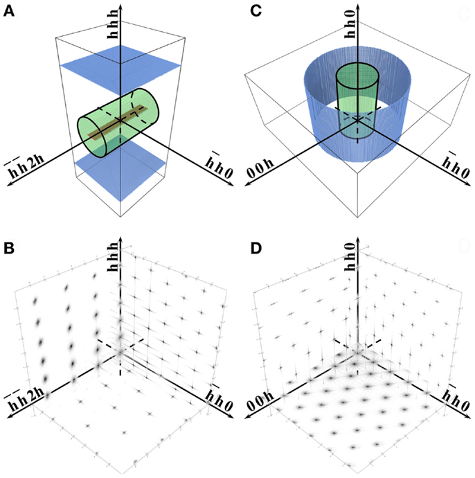
Figure 1. Schematic description of cylindrical nanocrystals with edge (A) and screw (C) dislocations embedded in corresponding parallelepiped volumes treated by Molecular Dynamics [30 × 30 × 46 nm for (A) and 40 × 40 × 28.7 nm for (B)]. Surfaces in color are left free during MD equilibration, whereas PBCs are applied to the other surfaces: along and in (A), and along [hh0] in (C). Corresponding reciprocal space cross-sections of diffracted intensity are shown below: (B) for cylinder in (A), and (D) for cylinder in (C).
A time-average of the arrangement in space of the atomic positions was computed along the time trajectory, so to cancel the thermal effects out (Leonardi et al., 2011); this Time Averaged Microstructure (TAM) was then used to calculate powder diffraction patterns by the Debye scattering equation (DSE) (Debye, 1915; Gelisio et al., 2010), using the atomic coordinates in the cylindrical regions shown in Figure 1 (black line wireframe). As in the Krivoglaz–Wilkens approach, dislocations were always straight lines running parallel to the cylinder axis. Effects related to the position of the dislocation line were also considered, randomly displacing the cylinder region of interest and then considering corresponding powder patterns and averages. For comparison, similar procedures were carried out for the same cylindrical regions without any line defect. To assess the role of domain size and surface, few other regions were also considered for different domain shapes (cube and sphere) and for smaller systems. In particular a D = 20 nm, H = 28.7 nm cylindrical domain was generated, both as a smaller version of that shown in Figure 1C (D = 40 nm, H = 28.7 nm), and carved out from it.
Results
Figure 2 shows the isotropic (volumetric) and deviatoric strain fields for Pd bulk nanocrystals containing edge or screw dislocations. As expected, the edge case gives compressive/tensile (Figure 2A) and deviatoric (Figure 2B) strains, whereas the screw dislocation gives a predominantly deviatoric strain (Figure 2D). In both cases, the dislocation line splits in partials, according to the known reaction: , a feature especially visible for the edge dislocation. The separation distance between edge partials (about 4 nm) is sensibly larger than predicted by simple considerations on surface energy of the faulted region between partials (~1 nm) (Hull and Bacon, 1965), but is well in agreement with other, more recent literature values (Hunter et al., 2011). Also the screw dislocation is not exactly as an ideal straight line, even though splitting and other deviations are less pronounced than in the edge case.
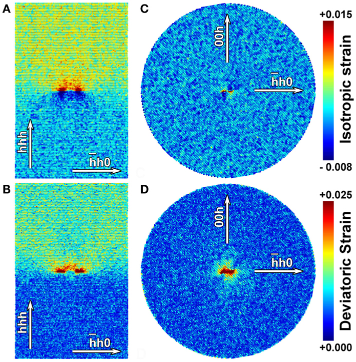
Figure 2. Isotropic (A,C) and deviatoric (B,D) strain fields in the systems of Figure 1. Cross-sections refer to Pd nanocrystals with edge (left column) and screw (right column) dislocation lines, respectively.
Extended dislocations have a complex effect on diffraction, well beyond a simple broadening of the diffraction line profiles. Figure 3 shows the XRD intensity distribution on three orthogonal cross-sections of the reciprocal space (RS) for cylindrical nanocrystals containing edge (Figure 3, De, Ee, and Fe) or screw (Figure 3, Ds, Es, and Fs) dislocations. It is also shown the intensity scattered by the corresponding perfect nanocrystal, i.e., the same cylinder with no line defect and atoms in perfect, ideal positions (Figure 3, Ae, Be, Ce and As, Bs, Cs for edge and screw, respectively). As expected, the strain field gives a growing effect with the distance from the RS origin. Depending on the Miller indices the intensity distribution around points is differently affected, and in some cases splits in two distinct regions. This feature is clearly observed in the edge case, along the direction, as an effect of the compressive and tensile strains, respectively above and below the dislocation slip plane (cf. Figures 1 and 2). Strain and faulted region in between the two partials affect in a rather complex way the distribution of intensity around all points in RS. Although mediated by the average over different orientations of the cylindrical domains, this complexity is expected to appear also in the corresponding powder patterns, as shown further below.
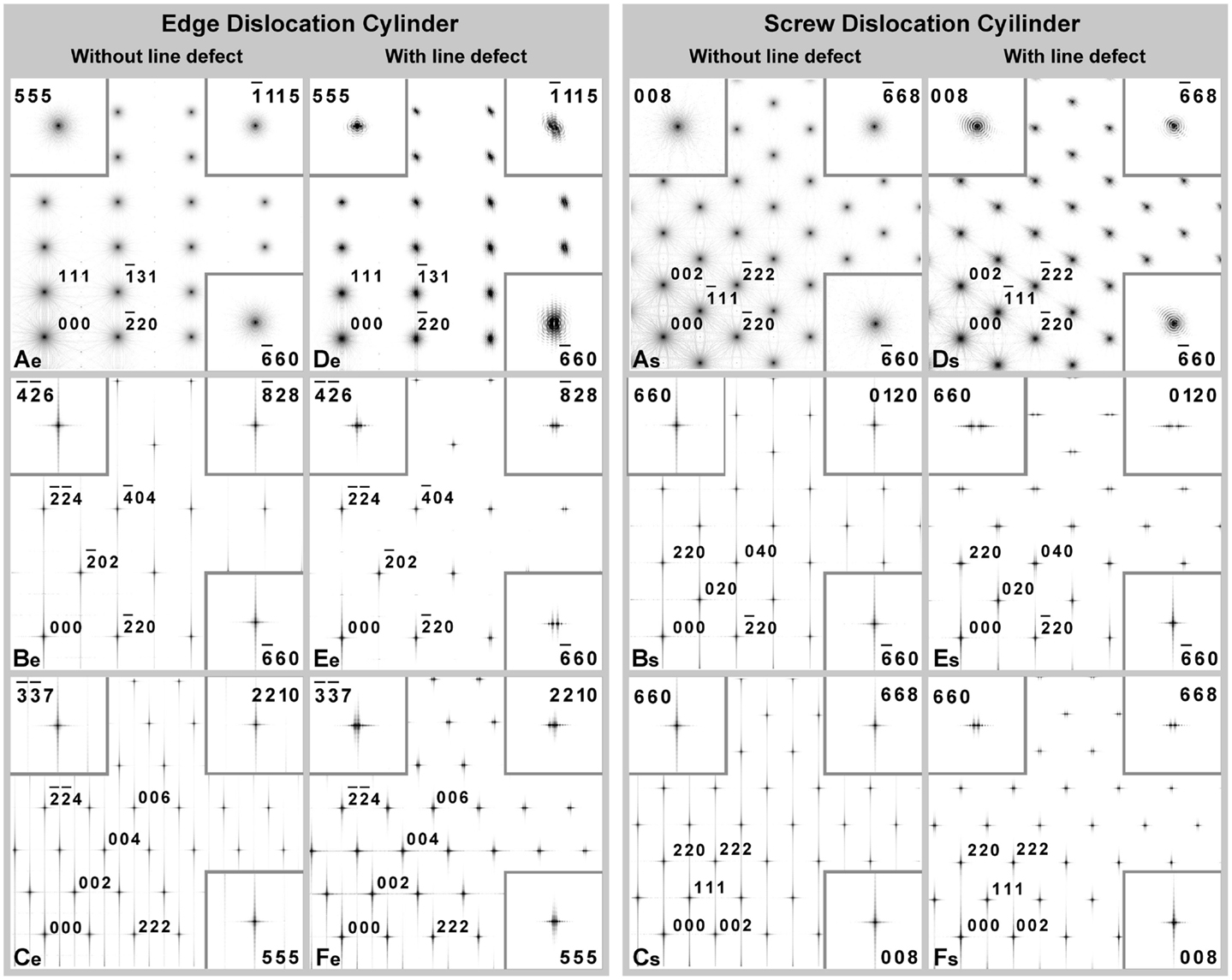
Figure 3. X-ray diffraction intensity distribution in reciprocal space. Three different cross-sections are shown for cylindrical Pd nanocrystals (D = H = 16 nm) with edge dislocation (De, Ee, and Fe) and screw dislocation (Ds, Es, and Fs). XRD intensity from corresponding cylinders without line defects are shown in (Ae, Be, and Ce) and (As, Bs, and Cs). Refer to Figure 1 for details on the cylindrical domains.
Another view-point on the atomic displacement effect of extended dislocations is provided by the Pair Distribution Function, shown in Figure 4. The same plot for perfect cylinders (i.e., domains with no line defects) gives an array of δ functions at all atom pair distances. These infinitely narrow bars, marked at the bottom of the plot of Figure 4, are broadened by the strain field of the dislocation lines, thus producing a sequence of distributions. Distribution widths for edge and screw cases are comparable, although the former gives additional peaks caused by the faulted region between the dislocation partials (Figures 1 and 2), which is responsible for a fraction of non-cubic sequence of atomic layer stacking. Effects on the diffraction pattern from a powder of dislocated cylindrical nanocrystals are therefore expected to be quite strong and different for the edge and screw dislocation cases.
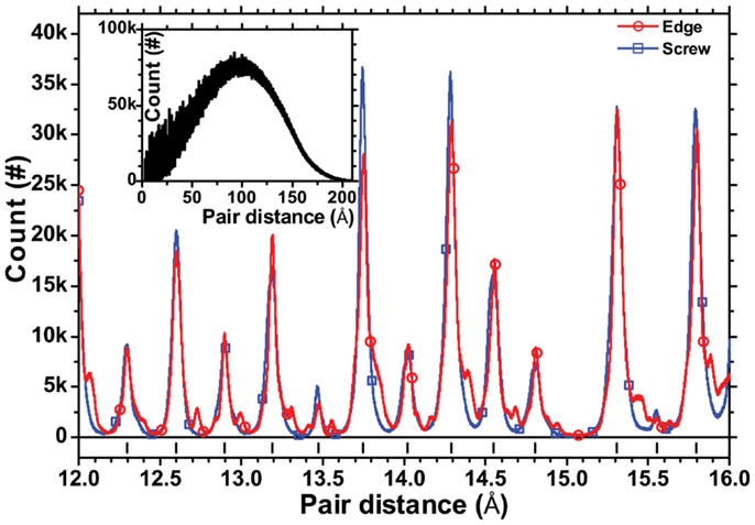
Figure 4. A selected range of the distribution function of atom pair distances in the Time Averaged Microstructure of cylindrical Pd nanocrystals (D = H = 16 nm) with edge (red circular dot) and screw (blue square dot) dislocation lines. The inset shows the trend across the whole range of distances.
Figure 5 shows the powder patterns simulated by the DSE from the TAM of cylindrical Pd nanocrystals (D = H = 16 nm) with edge or screw dislocations, and corresponding ideally perfect (“crystallographic”) nanocrystals. Despite the different orientation of the cylindrical nanocrystals (cf. Figure 1), the nanocrystal shape with equal height and diameter make the crystallographic powder patterns quite similar. Visible differences are caused by the dislocations. The screw case gives a predominant effect of broadening, whereas, the edge case gives broadening and shape effects, the latter caused by the non-cubic atomic layer stacking in the faulted region between edge partials. Such effects are stronger for Pd than Ir (Figure 6), as the separation between the partials, and therefore the extension of the stacking fault ribbon in the cylindrical microstructure, is larger for Pd than for Ir.
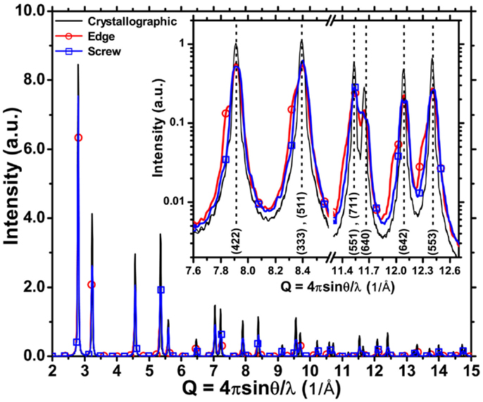
Figure 5. X-ray powder diffraction pattern simulated by DSE from the time averaged microstructure of cylindrical Pd nanocrystals (D = H = 16 nm) with edge (red circular dot), screw (blue square dot) dislocations, and from the corresponding ideally perfect (“crystallographic”) nanocrystals (black).
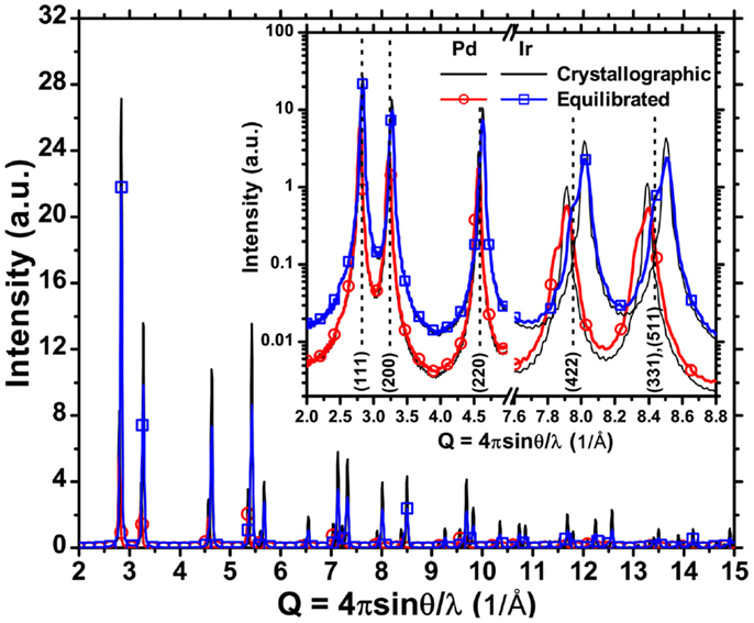
Figure 6. X-ray powder diffraction pattern simulated by DSE from the (“equilibrated”) TAM of cylindrical nanocrystals (D = H = 16 nm) with edge dislocations (line), and corresponding ideally perfect (“crystallographic”) nanocrystals (dash). Results are shown for Pd (red circular dot) and Ir (blue square dot), having respectively larger and smaller separation distance between partial dislocations.
Figure 7 shows the effect of position of the dislocation line. To be compatible with assumptions underlying Eq. 1, all dislocations were straight lines parallel to the cylinder axis. The position of the dislocation line has negligible effects in the case of screw dislocations, as a consequence of the mainly deviatoric strain field introduced in the TAM. Differences are quite strong for the edge dislocation case. Features originating from the more complex strain field of the edge type, and the stacking fault region associated to the two partials are always visible. It can only be noted that a pattern obtained by averaging those for different random positions of the edge line is quite similar to the pattern with the edge dislocation along the cylinder axis. However, even such average pattern is clearly affected by strong deviations from the pattern expected for an fcc metal phase.
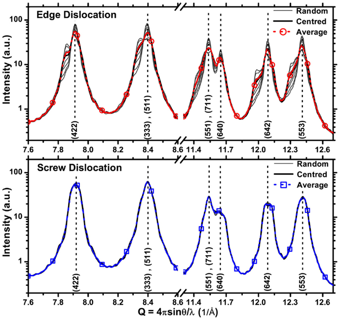
Figure 7. X-ray powder diffraction pattern simulated by DSE from the (“equilibrated”) TAM of cylindrical Pd nanocrystals (D = H = 16 nm) with edge (upper plot) and screw (lower plot) dislocation lines parallel to the cylinder axis, crossing the circular basis in different positions (center, random, and average).
Molecular Dynamics simulations can easily be extended to different nanocrystal sizes and shapes. Figure 8 shows the effect of changing the shape of the nanocrystal, following the same procedure described above for cylinders. Powder patterns from nanocrystals containing edge dislocations always show more complex details than the simple broadening provided by Eq. 1. The screw case seems qualitatively closer to the expected effects of Eq. 1, although some peaks present visible splitting [like the (642) line (Wilson, 1955) just above Q = 12 in Figure 8]. For the screw case in Figure 9, we also show the effect of changing the size of the cylindrical nanocrystal: largest effects are caused by changing the diameter, as can be easily explained considering that changing diameter acts on two dimensions, i.e., on the extension of the cylinder base.
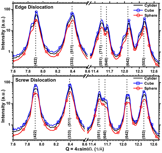
Figure 8. X-ray powder diffraction patterns simulated by DSE from the TAM of Pd nanocrystals containing edge (upper plot) and screw (lower plot) dislocation lines, with different shapes: cylinder (black), cube (blue square dot), and sphere (red circular dot).
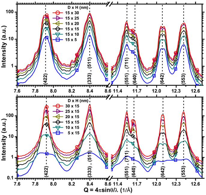
Figure 9. X-ray powder diffraction patterns simulated by DSE from the TAM of cylindrical Pd nanocrystals with screw dislocation lines, and different height H (upper plot) or diameter D (lower plot).
Discussion
The DSE powder patterns described so far can be considered as “experimental” diffraction data and analyzed by a state-of-the-art method, like WPPM (Scardi and Leoni, 2002; Scardi, 2008). Besides using Eq. 1 for refining the dislocation parameters (like ρ, Re, and ), WPPM can model nanocrystalline domains of virtually any size and shape (Leonardi et al., 2012), also considering the presence of stacking faults (Scardi and Leoni, 2002; Scardi, 2008) and other microstructural features responsible for line broadening effects (Scardi, 2008). For example, the complex effect of relaxation of the nanocrystal surface can be described by an additional “strain” profile component, with a corresponding FT given by
where accounts for strain anisotropy, referred to the Miller indices of the diffraction peak. Parameters a, b, c can be adjusted to model the strain field and anisotropy.
The FT of the overall diffraction line profile, A(L), can then be written as a product of all required FTs (Scardi, 2008):
where is the FT of the domain size effect, known in closed analytical form for a cylindrical shape (Langford and Louer, 1982). Therefore, in this specific case, besides refinable parameters of Eqs. 1 and 3 includes height (H) and base diameter (D) of the cylindrical domain, and adjustable parameters a, b, c of Eq. 2. If necessary, the effect of stacking faults in reasonably low concentration can be described by a component given by Warren’s theory for faulted fcc metal structures (Warren, 1990; Scardi, 2008).
Results of Figures 5–8 and relevant discussion point out the difficulty in modeling the pattern of a powder of cylindrical domains with edge dislocations. The traditional approach, underlying also Eq. 3, considers a perfect cylindrical fcc domain with defects; such a perturbation approach seems little convincing here, as it cannot account in any simple and accurate way for the faulted region between the two partials, with the corresponding hexagonal sequences, and the complex strain field, strongly dependent on split of the dislocation line in partials and their position inside the domain (cf. Figure 7). The screw dislocation case seems more “well-behaving,” i.e., closer to the assumptions of Krivoglaz–Wilkens theory, mostly involving a line broadening effect. Therefore, in the following we focus on the screw case only, analyzing the corresponding powder patterns by the WPPM approach as described by Eq. 3.
Figure 10 shows the modeling results for two different powders of cylindrical domains, respectively D = 40/H = 28.7 nm (Figures 10A–C) and D = 20/H = 28.7 nm (Figures 10D–F). The result for ideal cylindrical domains (Figures 10A,D), i.e., with Pd atoms positioned according to ideal fcc structure, no dislocations, and no surface relaxation, is very good, as expected in case of domain size broadening effects only (Leonardi et al., 2012). Small deviations between DSE pattern and WPPM are expected, owing to the different hypotheses underlying DSE and WPMM, as the former is based on an intrinsically discrete, atomistic model, whereas, the last considers crystalline domains as ideal solid models, i.e., cylinders with a smooth surface [details can be found in Beyerlein et al. (2011)].
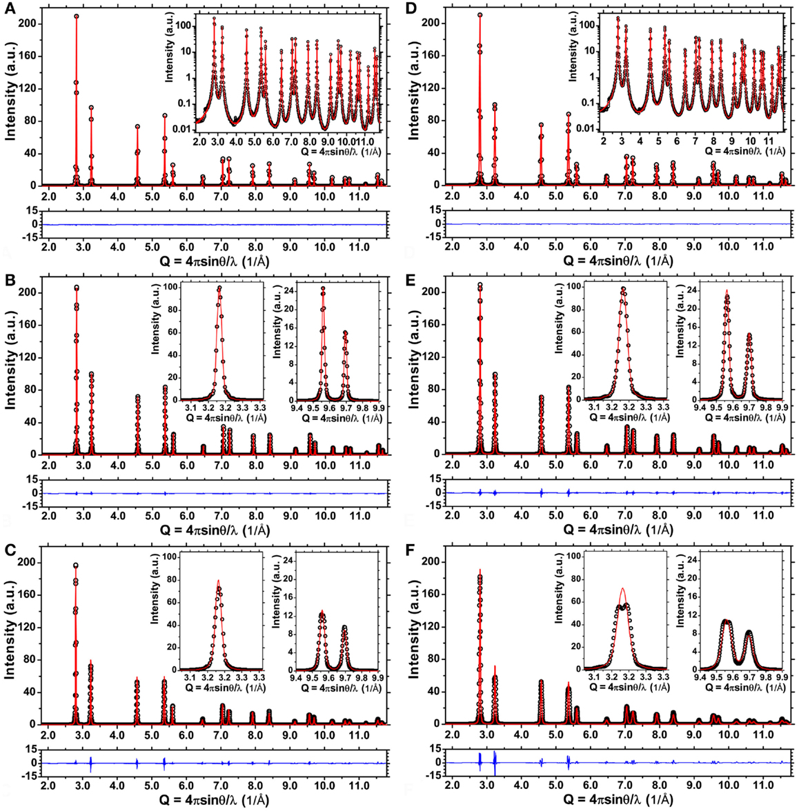
Figure 10. Debye scattering equation powder patterns (dot), WPPM result (line) and difference between the two (line, below) for Pd ideal cylindrical domains, D = 40 nm/H = 28.7 nm (Left) and D = 20 nm/H = 28.7 nm (Right): ideal cylindrical domain (A,D), same domain after equilibration (energy minimization) (B,E), and with screw dislocation along the axis after equilibration (C,F). Details are shown in the insets.
The modeling is still reasonably good when the atomistic model of the same cylindrical domain is equilibrated before, generating the pattern by the DSE (Figures 10B,E). Energy minimization leads to a strain broadening effect caused by the relaxation of the free surface, which adds to the size broadening effect from the finite cylindrical domain. The effect is well represented by the model of Eq. 2. The WPPM result, instead, is much less satisfactory for the cylindrical domain containing a screw dislocation along the axis, showing marked and systematic deviations from the DSE pattern (Figures 10C,F): peak width is reasonably matched but details of the peak profile shape are definitely not reproduced. More in particular, the model of Eq. 1 is unstable: even if the contrast factor is fixed to the expected value for a screw dislocation (for the primary slip system of Pd, {111}, ) when ρ and Re are both allowed to vary, the last diverges (>1012 nm). In the case of the smaller cylinder (D = 20/H = 28.7 nm), even the cylinder height, when freely refined, tends to wrong (smaller) values. Such instability and drift of the refinement toward wrong values is partly due to the intrinsic correlation between parameters – quite clearly, between ρ and Re – but is also a result of the complexity of the strain field, which is not fully captured by the model of Eq. 1.
The modeling improves if more parameters are fixed. Indeed, besides the contrast factor we can fix D and H to the model values (for the specific cylinder considered), and also set the dislocation density to the expected value, given by the ratio between dislocation length and cylinder volume: . This gives values of 0.796 × 10⁻¹⁵ m−2 and 3.183 × 10⁻¹⁵ m−2, respectively for D = 40/H = 28.7 nm and D = 20/H = 28.7 nm cylinders.
Then the only microstructural parameter to be refined, besides unit cell parameters, is the effective outer cut-off radius. This is how the refinements for the larger cylinder in Figures 10C,F were obtained. For a more robust convergence we refined together the patterns of both cylinders, without and with screw dislocation (Figures 10B,C, respectively), thus refining the same values of a, b, and c in Eq. 3, together with Re for the cylinder with screw dislocation. The same procedure was repeated for the smaller cylinder (Figures 10E,F).
Best value of Re for the D = 40/H = 28.7 nm cylinder is 41.3(1) nm, quite close to twice the cylinder radius. This value is in close agreement with Wilkens model of Eq. 1, where line defects are assumed to be inside the so-called “restrictedly random dislocations regions,” whose radius (Rp) is related to our definition of Re as Re ≈ 2Rp = D [see Wilkens (1970b) for definitions, and Armstrong et al. (2006) for a more recent review on the validity of Eq. 1 and relation between Re and physical lengths of crystalline domains containing dislocations].
For the smaller cylinder, D = 20/H = 28.7 nm, Re is proportionally larger, 26.0(1) nm, but still not far from the expected value of 2Rp. It is therefore verified the correctness of the hypotheses underlying the Krivoglaz–Wilkens model, although Eq. 1 can be unstable when trying to refine all parameters, especially those which correlate more strongly. The agreement with the model hypotheses increases with the domain size, and we can expect the model to be exact in the limit of very large diameters. Deviations in smaller domains are partly related to the non-ideality of dislocations, but also reflect the effect of the dislocation core region, which in the Krivoglaz–Wilkens model is excluded by an inner cut-off radius (Wilkens, 1970a,b).
Strain effects on the diffraction line profile analysis can be described by an r.m.s. strain (or microstrain) plot, originally proposed by Warren and Averbach (1950), Warren (1990). This plot, shown in Figure 11 for both models of cylindrical domains containing a screw dislocation, provides the r.m.s. strain (, the width of the strain distribution) over different distances L inside the crystalline domain, taken along the scattering vector direction; as a consequence, the microstrain depends on the crystallographic direction. Figure 11 shows trends along , and for both strain components, respectively due to the dislocation (line) and to the grain boundary relaxation (dash). Strain values increase for smaller domain sizes, following the corresponding increase in dislocation density [from Eq. 1, ], whereas the effect of the grain boundary strain decreases with increasing diameter.
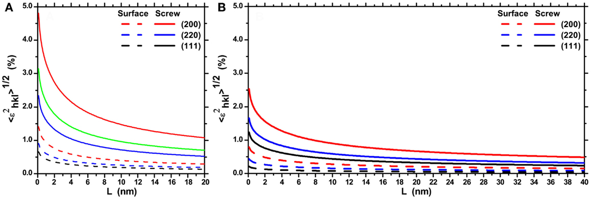
Figure 11. Plot of the r.m.s. strain as a function of the Fourier length, L, taken along the scattering vector direction inside the cylindrical domains: D = 20 nm/H = 28.7 nm (A) and D = 40 nm/H = 28.7 nm (B). Trends refer to the dislocation strain (screw, line) and surface relaxation strain (surface, dash) along different crystallographic directions.
To better assess the effect of the cylindrical grain boundary, we carved a D = 20 nm/H = 28.7 nm cylinder from the larger one containing a screw dislocation along its axis, and then generated the powder pattern by the DSE. The WPPM analysis was made considering only the strain effect from the dislocation, with same contrast factor, fixed domain size and dislocation density (3.183 × 10⁻¹⁵ m−2). The result gave Re = 26.4(1) nm, nearly the same value refined for the same cylinder with surface relaxation effect (Figures 10E,F), thus confirming that Re approaches the expected 2Rp value if all conditions of the Wilkens model are verified. Also in this case, however, the instability of Eq. (1) is confirmed, as a free refinement of all parameters gives diverging values of Re, a dislocation density much smaller than expected, and a wrong height of the cylindrical domain.
It is interesting to consider the results shown so far in terms of the main strain component in the studied systems. Figure 12 shows the deviatoric strain as a function of the radial distance from the cylinder axis, which is also the position of the screw dislocation line (cf. Figure 1C).
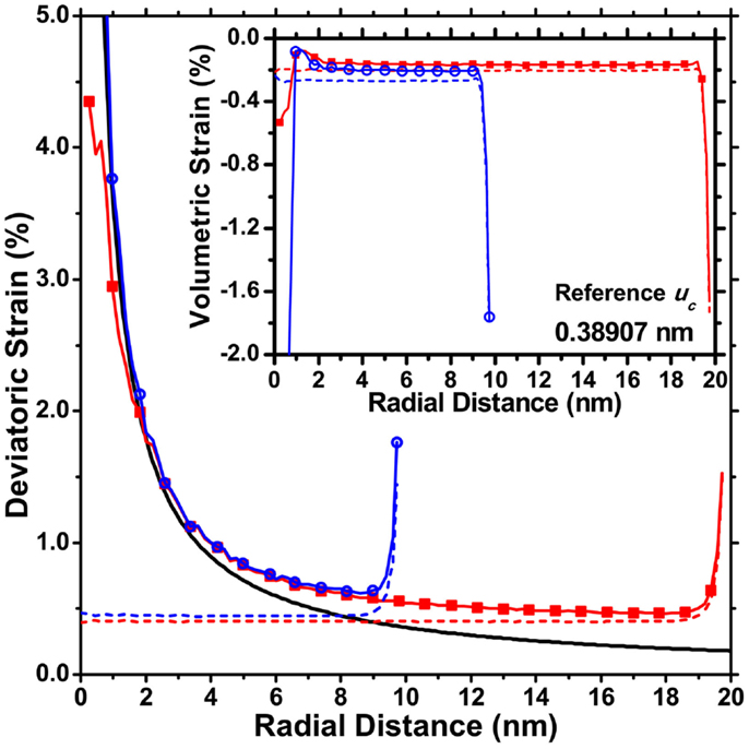
Figure 12. Deviatoric strain components as a function of the distance from the dislocation axis (cylinder axis), for an ideal screw dislocation (black line). It is also shown the trend obtained by MD for the D = 20 nm/H = 28.7 nm (blue circle) and D = 40 nm/H = 28.7 nm (red square) cylinders with dislocation and without dislocation, thus showing the effect of surface relaxation (dash lines). The inset shows the volumetric strain component.
The strain for an ideal dislocation (Hull and Bacon, 1965) is shown together with the values obtained from MD, for both cylindrical domains (D = 20 nm/H = 28.7 nm and D = 40 nm/H = 28.7 nm) with and without screw dislocation. Apart from the dislocation core region, where the continuum mechanics expression diverges while the MD values stay finite, it is quite evident that the MD trends for domains with screw dislocations result from a combination of the strain from the dislocation with that from the surface relaxation effect. The last steeply decays from the surface toward the inside the domain, and tends to decrease for increasing diameter of the cylindrical domain.
Conclusion
Differences between real dislocations and the idealized models of continuum mechanics, become significant when dislocations are confined in nanocrystalline domains. MD simulations show that the traditional continuum mechanics expressions for the strain field only approximately agree with the actual strain field. This was demonstrated for the simple case of straight dislocations in cylindrical Pd nanocrystal, a condition closely matching the hypotheses underlying the Krivoglaz–Wilkens theory on dislocation effects in diffraction. Discrepancies between theory and MD simulations are especially evident for edge dislocations, as an effect of the split into partials and the corresponding stacking faults in between, responsible for a region of non-hexagonal layer stacking. Under these conditions, the traditional perturbation approach, based on a cubic (fcc) Pd phase with deformation caused by lattice defects, seems not appropriate to model XRD patterns obtained from MD simulations. Further discrepancy is observed if the edge dislocation line does not lay along the axis of the cylindrical domain.
The screw case seems more similar and compatible with the Krivoglaz–Wilkens theory. Diffraction patterns generated by MD seem little affected by the position of the dislocation line in the cylindrical domain, and the main effect is a broadening of the diffraction lines, as predicted by the theory. If all parameters of the system – cylindrical domain height and diameter, contrast factor of the screw dislocation in the primary slip system of Pd, dislocation density as given by line defect length divided by the cylinder volume – are fixed, then the dislocation outer cut-off radius is found in good agreement with the Wilkens model for restrictedly random dislocations: Re is about 10–20% larger than the diameter (2Rp) of the restrictedly random regions, the discrepancy decreasing for increasing cylinder diameter.
Despite this positive result, if the powder diffraction pattern generated from the MD simulation is modeled according to the Wilkens theory, the non-ideality of the dislocations and the intrinsic correlations between parameters lead to a strong instability. If all microstructural parameters are allowed to vary without constraints, the outer cut-off radius tends to diverge, leading all other parameters to wrong values. It is therefore likely that significant errors may occur in the experimental practice, when Wilkens model is applied to real materials, e.g., plastically deformed metals; applying restrictions to some parameters, possibly exploiting evidence from other techniques, might significantly help to obtain reliable results from the analysis of the diffraction patterns. Effects are expected to be increasingly significant for smaller domain sizes. Further studies will be required to shed light on this important issue, in the effort to provide a realistic modeling of polycrystalline materials with lattice defects.
Conflict of Interest Statement
The authors declare that the research was conducted in the absence of any commercial or financial relationships that could be construed as a potential conflict of interest.
References
Armstrong, N., Leoni, M., and Scardi, P. (2006). Considerations concerning Wilkens’ theory of dislocation line-broadening. Z. Kristallogr. Suppl. 23, 81–86. doi: 10.1524/zksu.2006.suppl_23.81
Beyerlein, K. R., Snyder, R. L., and Scardi, P. (2011). Powder diffraction line profiles from the size and shape of nanocrystallites. J. Appl. Crystallogr. 44, 945–953. doi:10.1107/S0021889811030743
Bulatov, V., Farid, F. A., Ladislas, K., Benoit, D., and Sidney, Y. (1998). Connecting atomistic and mesoscale simulations of crystal plasticity. Nature 391, 669–672. doi:10.1038/35577
Daw, M. S., and Baskes, M. I. (1984). Embedded-atom method: derivation and application to impurities, surfaces, and other defects in metals. Phys. Rev. B 29, 6443–6453. doi:10.1103/PhysRevB.29.6443
Debye, P. (1915). Zerstreuung von Röntgenstrahlen. Ann. Phys. 351, 809–823. doi:10.1002/andp.19153510606
Foiles, S. M., Baskes, M. I., and Daw, M. S. (1986). Embedded-atom-method functions for the fcc metals Cu, Ag, Au, Ni, Pd, Pt, and their alloys. Phy. Rev. B 33, 7983–7991. doi:10.1103/PhysRevB.33.7983
Gelisio, L., Azanza Ricardo, C. L., Leoni, M., and Scardi, P. (2010). Real-space calculation of powder diffraction patterns on graphics processing units. J. Appl. Crystallogr. 43, 647–653. doi:10.1107/S0021889810005133
Groma, I. (1998). X-ray line broadening due to an inhomogeneous dislocation distribution. Phy. Rev. B 57, 7535–7542. doi:10.1103/PhysRevB.57.7535
Groma, I., and Székely, F. (2000). Analysis of the asymptotic properties of X-ray line broadening caused by dislocations. J. Appl. Crystallogr. 33, 1329–1334. doi:10.1107/S002188980001058X
Hunter, A., Beyerlein, I. J., Germann, T. C., and Koslowski, M. (2011). Influence of the stacking fault energy surface on partial dislocations in fcc metals with a three-dimensional phase field dislocations dynamics model. Phys. Rev. B 84, 144108. doi:10.1103/PhysRevB.84.144108
Jacobsen, K. W., and Schiotz, J. (2002). Computational materials science: nanoscale plasticity. Nat. Mater. 1, 15–16. doi:10.1038/nmat718
Kaganer, V. M., and Sabelfeld, K. K. (2011). Short range correlations of misfit dislocations in the X-ray diffraction peaks. Phys. Status Solidi A 208, 2563–2566. doi:10.1002/pssa.201184255
Kaganer, V. M., and Sabelfeld, K. K. (2014). Strain distributions and diffraction peak profiles from crystals with dislocations. Acta Cryst. A 70, 457–471. doi:10.1107/S2053273314011139
Pubmed Abstract | Pubmed Full Text | CrossRef Full Text | Google Scholar
Kamminga, J.-D., and Delhez, R. (2000). Calculation of diffraction line profiles from specimens with dislocations. A comparison of analytical models with computer simulations. J. Appl. Crystallogr. 33, 1122–1127. doi:10.1107/S0021889800006750
Klimanek, P., and Kuzel, R. (1988). X-ray diffraction line broadening due to dislocations in non-cubic materials. I. General considerations and the case of elastic isotropy applied to hexagonal crystals. J. Appl. Crystallogr. 21, 59–66. doi:10.1107/S0021889887009580
Klug, H. P., and Leroy, E. A. (1974). X-Ray Diffraction Procedures for Polycrystalline and Amorphous Materials. New York, NY: Wiley.
Kuzel, R., and Klimanek, P. (1988). X-ray diffraction line broadening due to dislocations in non-cubic materials. II. The case of elastic anisotropy applied to hexagonal crystals. J. Appl. Crystallogr. 21, 363–368. doi:10.1107/S002188988800336X
Kuzel, R., and Klimanek, P. (1989). X-ray diffraction line broadening due to dislocations in non-cubic crystalline materials. III. Experimental results for plastically deformed zirconium. J. Appl. Crystallogr. 22, 299–307. doi:10.1107/S0021889889001585
Langford, I. J., and Louer, D. (1982). Diffraction line profiles and scherrer constants for materials with cylindrical crystallites. J. Appl. Crystallogr. 15, 20–26. doi:10.1107/S0021889882011297
Leonardi, A., Beyerlein, K. R., Xu, T., Li, M., Leoni, M., and Scardi, P. (2011). Microstrain in nanocrystalline samples from atomistic simulation. Z. Kristallogr. Proc. 1, 37–42. doi:10.1524/zkpr.2011.0005
Leonardi, A., Leoni, M., and Scardi, P. (2012). Common volume functions and diffraction line profiles of polyhedral domains. J. Appl. Crystallogr. 45, 1162–1172. doi:10.1107/S0021889812039283
Li, X., Wei, Y., Lu, L., and Gao, H. (2010). Dislocation nucleation governed softening and maximum strength in nano-twinned metals. Nature 464, 877–880. doi:10.1038/nature08929
Pubmed Abstract | Pubmed Full Text | CrossRef Full Text | Google Scholar
Martinez-Garcia, J., Leoni, M., and Scardi, P. (2009). A general approach for determining the diffraction contrast factor of straight-line dislocations. Acta Cryst. A 65, 109–119. doi:10.1107/S010876730804186X
Pubmed Abstract | Pubmed Full Text | CrossRef Full Text | Google Scholar
Mittemeijer, E. J., and Scardi, P. (2004). Diffraction Analysis of the Microstructure of Materials. Berlin: Springer.
Plimpton, S. (1995). Fast parallel algorithms for short-range molecular dynamics. J. Comput. Phys. 117, 1–19. doi:10.1006/jcph.1995.1039
Scardi, P. (2008). “Microstructural properties: lattice defects and domain size effects,” in Powder Diffraction: Theory and Practice, eds R. E. Dinnebier and S. J. L. Billinge (Oxford: Royal Society of Chemistry), 378–416.
Scardi, P., and Leoni, M. (2002). Whole powder pattern modelling. Acta Cryst. A 58, 190–200. doi:10.1107/S0108767301021298
Scardi, P., Leoni, M., and Delhez, R. (2004). Line broadening analysis using integral breadth methods: a critical review. J. Appl. Crystallogr. 37, 381–390. doi:10.1107/S0021889804004583
Scardi, P., Leoni, M., and D’Incau, M. (2007). Whole powder pattern modelling of cubic metal powders deformed by high energy milling. Z. Kristallogr. 222, 129–135. doi:10.1524/zkri.2007.222.3-4.129
Scherrer, P. (1918). Bestimmung der Grösse und der inneren Struktur von Kolloidteilchen mittels Röntgensrahlen. Nachr. Ges. Wiss. Gottingen Math. Phys. Kl. 98.
Sheng, H. W., Kramer, M. J., Cadien, A., Fujita, T., and Chen, M. W. (2011). Highly optimized embedded-atom-method potentials for fourteen fcc metals. Phy. Rev. B 83, 134118. doi:10.1103/PhysRevB.83.134118
Snyder, R. L., Fiala, J., and Bunge, H.-J. (1999). Defect and Microstructure Analysis by Diffraction. New York, NY: Oxford University Press.
Ungar, T. (2008). Dislocation model of strain anisotropy. Powder Diffr. 23, 125–132. doi:10.1154/1.2918549
Ungar, T., Ott, S., Sanders, P. G., Borbely, A., and Weertman, J. R. (1998). Dislocations, grain size and planar faults in nanostructured copper determined by high resolution X-ray diffraction and a new procedure of peak profile analysis. Acta Mater. 46, 3693–3699. doi:10.1016/S1359-6454(98)00001-9
Warren, B. E., and Averbach, B. L. (1950). The effect of cold-work distortion on X-ray patterns. J. Appl. Phys. 21, 595–599. doi:10.1063/1.1699713
Wilkens, M. (1970a). The determination of density and distribution of dislocations in deformed single crystals from broadened X-ray diffraction profiles. Phys. Status Solidi A 2, 359–370. doi:10.1002/pssa.19700020224
Wilkens, M. (1970b). “Theoretical aspects of kinematical X-ray diffraction profiles from crystals containing dislocation distributions,” in Fundamental Aspects of Dislocation Theory, eds J. A. Simmons, R. de Wit, and R. Bullough (Washington, DC: NBS Spec. Publ.), 317.
Wilson, A. J. C. (1955). The effects of dislocations on X-ray diffraction. Il Nuovo Cimento 1, 277–283. doi:10.1007/BF02900634
Yamakov, V., Wolf, D., Phillpot, S. R., Mukherjee, A. K., and Gleiter, H. (2002). Aluminium reveals some surprising behaviour of nanocrystalline aluminium by molecular-dynamics simulation. Nat. Mater. 1, 1–4. doi:10.1038/nmat700
Pubmed Abstract | Pubmed Full Text | CrossRef Full Text | Google Scholar
Yamakov, V., Wolf, D., Phillpot, S. R., Mukherjee, A. K., and Gleiter, H. (2004). Deformation-mechanism map for nanocrystalline metals by molecular-dynamics simulation. Nat. Mater. 3, 43–47. doi:10.1038/nmat1035
Pubmed Abstract | Pubmed Full Text | CrossRef Full Text | Google Scholar
Keywords: x-ray powder diffraction, line profile analysis, nanocrystalline materials, dislocations, molecular dynamics simulation
Citation: Leonardi A and Scardi P (2015) Atomistic model of metal nanocrystals with line defects: contribution to diffraction line profile. Front. Mater. 1:37. doi: 10.3389/fmats.2014.00037
Received: 13 November 2014; Accepted: 22 December 2014;
Published online: 03 February 2015.
Edited by:
Simone Taioli, Bruno Kessler Foundation, ItalyReviewed by:
Andrea Piccolroaz, University of Trento, ItalyShangchao Lin, Florida State University, USA
Copyright: © 2015 Leonardi and Scardi. This is an open-access article distributed under the terms of the Creative Commons Attribution License (CC BY). The use, distribution or reproduction in other forums is permitted, provided the original author(s) or licensor are credited and that the original publication in this journal is cited, in accordance with accepted academic practice. No use, distribution or reproduction is permitted which does not comply with these terms.
*Correspondence: Paolo Scardi, Department of Civil, Environmental and Mechanical Engineering, University of Trento, Via Mesiano 77, Trento 38123, Italy e-mail: paolo.scardi@unitn.it