Switchable surfactant-assisted carbon nanotube coatings: innovation through pH shift
 Carlos Sanchís
 Ramiro Ruiz-Rosas
 Ángel Berenguer-Murcia
 Emilia Morallón
 Diego Cazorla-Amorós
- 1Departamento de Química-Física e Instituto Universitario de Materiales, University of Alicante, Alicante, Spain
- 2Departamento de Química Inorgánica e Instituto Universitario de Materiales, University of Alicante, Alicante, Spain
The inner surface of fused-silica capillaries has been coated with a dense/homogeneous coating of commercial multi-wall carbon nanotubes (MWCNTs) using a stable ink as deposit precursor. Solubilization of the MWCNTs was achieved in water/ethanol/dimethylformamide by the action of a surfactant, which can switch between a neutral or an ionic form depending on the pH of the medium, which thus becomes the driving force for the entire deposition process. Careful control of the experimental conditions has allowed us to selectively deposit CNTs on the inner surface of insulating silica capillaries by a simple, reproducible, and easily adaptable method.
Introduction
Due to their exceptional properties in a wide variety of fields, carbon nanomaterials have attracted substantial attention. Carbon nanotubes (CNTs) and graphene in particular show great promise in applications as varied as solid phase separation, sensors and actuators, catalysts and catalysts support, and materials for energy storage. Due to their production volume, such nanomaterials cannot be envisaged for high-volume applications in which a large amount of sample would be required. Nevertheless, consumer-end and miniaturized devices offer an attractive alternative for the development of new configurations, which may outperform already existing devices. In this respect, the field of microreactor technology and microfluidics have experienced a noticeable boost due to significant improvements in the design of flow devices (de Mello, 2006; Whitesides, 2006) as well as a deeper understanding of chemical transformations within confined regions (Yoshida et al., 2005; Hartman and Jensen, 2009; Hartman et al., 2011; Hessel et al., 2013). However, the implementation of microreactors as a competitive alternative depends highly upon the ability to deliver functional stationary phases within the microchannel confines (Peterson, 2005). To achieve this particular target, new strategies must still be developed in order to enable the generation of homogeneous coatings with the desired thickness throughout the microfluidic pipes without obstructing the system.
Among the many applications, which are currently being explored for the implementation of carbon nanomaterials-based systems and devices, we may find the preparation of conducting fibers in order to improve their durability (Xiang et al., 2012), the development of laser-resistant coatings (Bhandavat et al., 2013), the fabrication of films for heat transfer enhancement (Sujith Kumar et al., 2014), or the synthesis of materials capable of acting as sensors (García-Aguilar et al., 2014) or biosensors (Papper et al., 2013). All these applications have in common that they require the deposition of a film or coating as homogeneous as possible on a suitable substrate, which in turn ultimately depends on the preparation of stable carbon nanomaterials suspensions. Concerning the preparation of suspensions, the literature presents many solvents, which have been employed in order to obtain suitable CNT suspensions, including ethanol, acetone, benzene, chloroform, N,N-dimethylformamide (DMF), isopropanol, tetrahydrofuran (THF), or toluene (Gábor et al., 2007). Given that chemical processes have nowadays a growing tendency to become “green,” the solvent of choice for any application should be water. Given their chemical nature, carbon-based nanomaterials show very poor dispersability in water. To overcome this problem, two main strategies have been reported in the literature: some authors have observed that the use of polymers, which combine a polar end (which may interact with water) with a non-polar end (which may interact with the carbon surface) in combination with a water-soluble polymer gives rise to stable suspensions of CNTs (or “inks,” as the authors point out) (Bravo-Sanchez et al., 2010; García-Aguilar et al., 2014). On the other hand, and so as not to introduce a large amount of surfactant species in the suspensions, other authors have made use of the surface chemistry of carbon nanomaterials, modifying their functional groups with a strong acid such as HNO3 or HNO3/H2SO4 mixtures, which in turn led to the preparation of stable suspensions, which are pH sensitive. Oxidized CNTs may be dispersed in water under neutral to alkaline pH due to the presence of acidic O-containing groups such as carboxylic acids, lactones, or phenols. At alkaline pH values, these groups release their acidic protons to give negatively charged CNTs where water molecules may easily disrupt the π–π stacking interactions, leading to the CNTs dispersion in the solvent (Thomas et al., 2005). Acidifying the solution leads to CNT coagulation due to the neutralization of these charges, as we have recently reported (Sanchís et al., 2014). However, some authors reported the possibility of obtaining stable suspensions of functionalized CNTs under low pH values after undergoing harsh oxidation treatments (Lee et al., 2009). The explanation for this phenomenon may be the presence of defects on the surface of the CNTs apart from the surface oxygen groups due to an aggressive oxidative treatment.
The present work addresses the preparation of CNT coatings inside microcapillary tubes using stable dispersions. A recent review points out the urge for further developments in the preparation procedures as well as understanding of the fundamentals in order to fully understand and develop the potential for carbon nanomaterials-based coatings in microenvironments (Mogensen and Kutter, 2012). Concerning the controlled preparation of CNT films or coatings on conventional devices, there are many examples in the literature using macroscopic or even patterned substrates. The two main techniques, which have hitherto been used are chemical vapor deposition (CVD) along with its variant plasma-enhanced chemical vapor deposition (PECVD) (Franklin and Dai, 2000; Berenguer-Murcia et al., 2009; Kumar and Ando, 2010) and electrophoretic deposition (EPD) (Gao et al., 2001; Boccaccini et al., 2006; Padmarj et al., 2009). While CVD would in principle be best suited for its adaptation in microdevices, there are several drawbacks that should be considered: (i) concerning the distribution of the catalytically active phase, achieving a homogenous distribution may not be straightforward in geometries more complex than flat (patterned or unpatterned) surfaces, which in turn raises the issue of how CNTs will grow in complex architectures due to inhomogeneous temperature and/or flow distribution and (ii) the range of temperatures used in the CNT preparation (in the range between 350 and 800°C) may affect the integrity of the reactor material, making it unsuitable for polymeric materials. Furthermore, in some cases, the requirement for additional post-treatment to either remove the metals present in native CNTs (purification) or grafting a supported catalyst may become a complicated step due to low accessibility and the corrosive action of acidic solutions used during purification.
Our group recently reported the preparation of homogeneous CNT deposits in the inner surface of commercial fused-silica capillary tubes by using a simple electrochemically assisted method for the precipitation of functionalized and Pd-decorated multi-wall carbon nanotubes (MWCNTs) from a stable dispersion (Sanchís et al., 2014). In this work, we aim to further explore and expand the possibilities of preparing CNT coatings by modifying them using a new family of materials known as “switchable” surfactants (Liu et al., 2006), whose surface chemical properties can be reversibly altered by the application of a trigger, allowing for reversibly stabilized dispersions. This switchability can be triggered by adding redox reagents, applying UV light, or, as is the case in this paper, altering the pH of the dispersion (Fowler et al., 2012). By using a suitable surfactant in a dilute solution, not only is it possible to prepare stable MWCNT suspensions but also to use them in a simple set-up for the deposition of controlled CNT coatings by which the bundling interactions, which hold the CNTs together may be easily overcome. It must be highlighted that contrary to our previous report, this particular methodology would not be limited by the geometry of the support (which in our case lies in the microscale) but could be easily scaled up to any given system in which we could homogeneously generate a pH shift. Our results indicate that by using a simple synthetic route, it is possible to prepare stable CNT suspensions, which may be applied in the preparation of CNT deposits by increasing the local pH inside an insulating capillary tube.
Materials and Methods
Switchable Surfactant Synthesis
The synthesis of the switchable surfactant N′-(4-decylphenyl)-N,N-dimethylacetamidine (DPDMA) was carried out as described in Fowler et al. (2012). In a general synthesis, 1 g of 4-decylaniline and 0.62 g of N,N-dimethylacetamide dimethylacetal were introduced in a round-bottom flask. The flask is heated at 60°C and swirled gently for 30 min to favor the mixing of the two reagents. Vacuum was then applied to remove the methanol that is generated upon reaction of the two precursors to give the switchable surfactant. The resulting product was an orange–yellow viscous liquid, which was transferred to an amber flask, sealed, and stored for further use under lightless conditions.
Preparation of MWCNTs Suspension
Commercial multi-walled CNTs (MWCNT, NanoBlack, Columbian Chemicals Co.) with an average diameter of 14 nm and lengths ranging from few hundred nanometers to several microns, and a measured BET area of 253 m2 g−1 (Domínguez-Domínguez et al., 2008) were used to prepare the inks described in this study. To prepare stable MWCNTs dispersions, the following steps were followed (as depicted in Scheme 1).
(1) A 0.5 mM solution of DPDMA in water was prepared (39 mg of DPDMA in 250 mL of water).
(2) An aliquot (160 mL) of this solution was transferred to a separate flask and CO2 was bubbled through this solution for 20 min in order to “activate” the DPDMA (see Figure 1). Under these conditions, in which the solvent is in contact with an atmosphere which is composed mostly of CO2, the pH is assumed to be between 4.5 and 5.0. Under acidic conditions, the acetamidine function of the molecule becomes protonated, and upon the formation of the bicarbonate salt the polymer becomes soluble in water. This behavior was evidenced by the absence of any turbidity and foam formation after approximately 10 min of bubbling CO2 through the solution.
(3) 160 mg of MWCNTs were added to the homogeneous solution of DPDMA and the mixture was sonicated in an ultrasound bath for a few minutes. CO2 was bubbled through the suspension for 30 more minutes after sonication.
(4) The resulting suspension was sonicated by means of an ultrasound probe (Bandelin Sonoplus GM2200) operating at a power of 100 W for two 30-s intervals.
(5) The resulting dispersion was centrifuged for 10 min at 4000 rpm in order to sediment all the MWCNTs, which had not been dispersed properly by the action of the active DPDMA.
(6) The top liquid layer (which corresponded to almost the totality of the initial aliquot volume) was separated and taken to a rotavapor at 60°C where the volume was reduced to 5–6 mL.
(7) The resulting dispersion was centrifuged again for 10 min at 4000 rpm. This suspension was then stored in a sealed glass jar for further use.
(8) The concentration of the resulting MWCNTs suspension was determined by UV–Vis spectrophotometry. For the estimation of the concentration, the π-plasmon band in UV analysis (245 nm) was used. The MWCNT dispersions were diluted 1:35 v/v in ultra-pure water and the UV–Vis–NIR spectrum was obtained in a JASCO (V-670) spectrophotometer. The difference between the absorbance at 1300 nm (taken as the baseline) and 350 nm was used as the defining parameter. This value multiplied by a factor 1.085 – the slope of the obtained calibration curve – gives a good estimate of the real concentration in milligram per milliliter, as we have reported elsewhere (Sanchís et al., 2014).
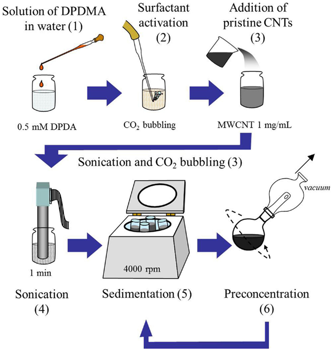
Scheme 1. Flow chart depicting the protocol for the preparation of MWCNTs suspensions. Note that the numbers indicate each representative step as detailed in the “Materials and Methods” section above.
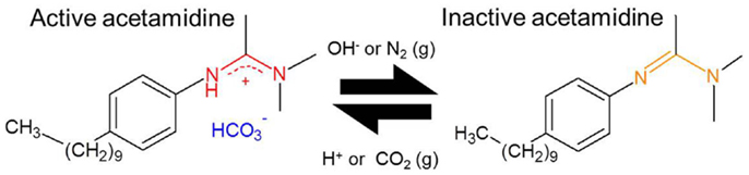
Figure 1. Scheme depicting the two forms of the switchable surfactant N′-(4-decylphenyl)-N,N-dimethylacetamidine (DPDMA). Left: water soluble form under acidic pH; right: organic soluble form under basic or neutral pH.
Electrochemically Assisted MWCNT Deposition
Deposition of the MWCNTs from the suspension prepared as described previously was carried in a set-up adapted from the one we reported earlier (Sanchís et al., 2014). An electrochemical column-shaped glass cell (10 cm long; 1.5 cm inner diameter) sealed by rubber septa at both ends was employed in this study. Commercial fused-silica capillary tubes, which are normally used for chromatography (Agilent, 250 μm inner diameter), were used as received without any further conditioning. Capillary tube segments employed were typically between 18 and 23 cm long. One end of the capillary tube was fixed to a syringe by means of epoxy adhesive, to allow its filling and emptying by using the syringe plunger, and then was inserted in the electrochemical cell through the upper septum. A Pd wire (Good fellow, 0.050 mm diameter) was passed through the whole length of the capillary segment, exiting the cell through the lower septum. Copper self-adhesive tape was used to immobilize the tip of the Pd inner electrode, providing a good fixation point for the electric contact. A coiled Pt wire (Good-fellow, 1.0 mm diameter) acted as the auxiliary – outer – electrode. The lower end of the capillary tube was set to almost reach the bottom of the glass cell, lying only a few millimeters away from both the septum and the outer electrode. In the present configuration, a very small volume (1–2 mL) of the MWCNT aqueous dispersion was required. Once the components were placed as indicated in Figure 2, a DC power source (Phywe) was connected to the electrodes, always setting the Pd – inner – electrode as the cathode (−). After a 1 h treatment at a voltage of 30 V, the capillary tube and the Pd wire were removed from the cell carefully. The inner solution was drawn out with the syringe and the tube was dried at 80°C under dynamic vacuum before carefully removing the wire to avoid scratching off the CNT coating.
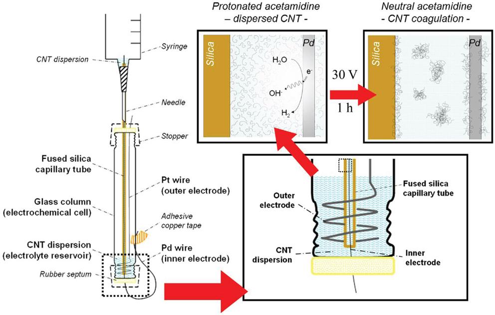
Figure 2. Illustration of the experimental set-up for the electrochemically assisted deposition of MWCNTs inside the capillary tubes used in this study. Insets show a close-up view (lower right) of the lower section of the cell and the suggested deposition process (top right).
Samples Characterization
The obtained samples were characterized by Scanning Electron Microscopy (SEM, JEOL JSM-840), with an acceleration voltage of 15 kV. The capillary segments were cut with a scalpel blade in order to uncover the inner surface of the capillary. Samples were sputtered with a thin gold layer prior to analysis.
Thermal analyses of the synthesized samples were performed in a differential scanning calorimetry–thermogravimetric analysis (DSC-TGA) equipment (TA Instruments, SDT Q-600) coupled to a mass spectrometer (Thermostar, Balzers, GSD 300 T3). Approximately 10 mg of each sample were heated up to 940°C (heating rate of 10°C min−1) under an air flow rate of 100 mL min−1. It must be noted that the polyimide coating of the fused silica was burned off prior to deposition of the MWCNTs for the sample to be suitable for thermogravimetric analysis. The quantification of the amount of CNT loaded in the inner surface of the capillary was estimated by determination of the CO2 evolved at high temperature during the experimental run, which was possible thanks to calibration of the 44 m/e− line by thermal decomposition of calcium oxalate. To avoid any interference, a dwell time of 60 min was applied during the TG–MS experiments when the temperature reached 450°C in order to ensure a complete removal of the DPDMA surfactant, which decomposes under oxidative thermal treatment at temperatures lower than 400°C.
Results
MWCNT Suspension Analysis
As detailed in the Materials and Methods section, in order to establish the concentration (milligram per milliliter) of the MWCNTs in water, the difference between the absorbance at 1300 nm (wavelength at which the baseline is taken) and 350 nm was used. According to our results, the use of a switchable polymer allowed for the preparation of suspensions containing up to 0.31 mg mL−1 in water. This value is lower than that reported in our previous work (Sanchís et al., 2014), where we used MWCNTs functionalized using ammonium persulfate (reaching concentrations of 0.9 mg mL−1) or functionalized MWCNTs decorated with polymer-protected Pd nanoparticles (reaching concentrations of 3.9 mg mL−1). However, it must be noted that, using this method, aggressive oxidation treatments that may damage the CNT or metal nanoparticles are not necessary to achieve the CNT suspensions. Nevertheless, the concentrations reported in this work are within the same range as other publications, which have studied the preparation of CNT inks (Thomas et al., 2005; Bravo-Sanchez et al., 2010).
Figure 3 shows the UV–Vis–NIR spectra of two different stable CNT dispersions analyzed in the present study, where the peak appearing at 220 nm corresponds to the absorption band of the surfactant DPDMA. The first suspension corresponds to the pristine MWCNT suspension obtained using a 0.5 mM solution DPDMA [Steps (1) to (5) in Section “Preparation of MWCNTs Suspension” of the present manuscript], and the second corresponds to the same suspension after undergoing evaporation in a rotavapor [Steps (1) to (7) in the aforementioned section]. The spectra clearly show that the concentration step has a beneficial effect in terms of MWCNT concentration in the suspension.
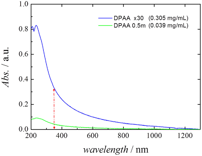
Figure 3. UV–Vis–NIR spectra of the different stable CNT dispersions employed in the present study, after 1:35 dilution in water. The difference between the absorbance at 1300 nm (baseline) and 350 nm was used as the indicative parameter for determining the CNT concentration.
Microscopy Analysis
In order to establish whether the MWCNTs had been successfully deposited on the inner surface of the capillaries to a significant degree, the samples were taken to an optical microscope (Leyca EZ4 HD). Figure 4 shows an image of the capillaries before (bottom) and after (top) undergoing electrochemically assisted deposition. The differences between the pristine and MWCNT-coated capillary clearly stand out as the top capillary has a gray matte appearance whereas the bottom capillary appears transparent and glossy, which evidences the deposition of the MWCNT coating. The homogeneity of the gray area may be taken as an indicative of the homogeneity of the coating.
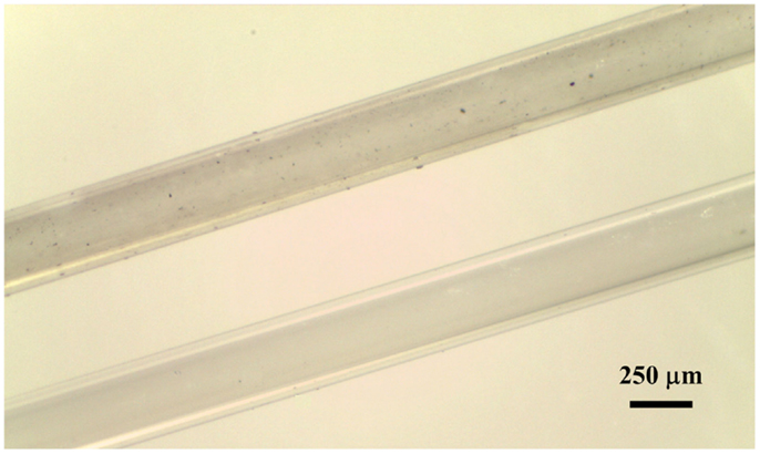
Figure 4. Optical microscopy image of the pristine silica capillary before (bottom) and after (top) undergoing EPD using a MWCNT suspension as described in the Materials and Methods section. Note that the orange polyimide coating covering the outer surface of the capillary has been burned off.
In order to better appreciate the coverage of the carbon nanotube coating, the samples were analyzed by SEM. Figure 5 shows two representative images of the inner surface of the silica capillary after undergoing electrochemically assisted deposition. The images clearly show that despite the fact that some of the surface of the capillary is not completely coated with CNTs, the coating appears to be homogeneous. As we reported in our previous work, given that the deposition mechanism is based on the bundling of the MWCNTs upon destabilization of the suspension, it is very difficult to avoid the appearance of CNT bundles on the surface of the capillary. By microscopy analysis, we have established that the CNTs cover a large fraction of the capillary surface, without a significant presence of large bundles, which may clog the capillary. From the presented representative optical and SEM images, the coating is largely homogeneous, with a few visible bundles whose size is always within the scale of a few microns. When the experiments were performed without activating the surfactant, a sparse deposit of large CNT bundles was observed, which corroborates that activation of the surfactant covering the CNTs is essential for the efficient deposition of CNT coatings.
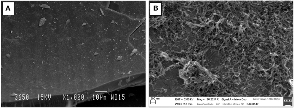
Figure 5. Electron micrographs showing (A) general top-view of the surface of the capillary after undergoing EPD (Scale bar 10 μm) and (B) close-up view of the CNT coating showing a large number of CNT bundles covering the capillary surface (Scale bar 200 nm).
TG–MS Experiments
While electron microscopy offers significant qualitative information about the degree of immobilization and distribution of CNTs on the silica walls, quantification of the amount of CNTs inside the capillary becomes a necessity in order to verify the usefulness of the deposition method reported in this work. Thus TG–MS experiments were performed under air atmosphere. As the flexible polyimide coating, which is found on the silica capillary, could also be oxidized at the same temperature range of the CNTs (results not shown), its removal was deemed critical to avoid any misleading results. In order to do this, the electrochemically assisted deposition was performed as described previously, but using a silica capillary tube where the polymer coating had been carefully burned off with a conventional flame burner. After deposition, the capillary tube sample was crushed into small segments in an agate mortar. The conditions and the equipment for TG–MS were the same as for those described in the Materials and Methods section, using synthetic air as sweep gas (H2O and CO2 <5 ppm). As Figure 6 clearly shows, a clear increase for the CO2 MS-signal is observed in the region between 600 and 800°C, corresponding to the burn-off of the carbon material. A control experiment performed with a polyimide-free capillary tube in the absence of the CNT deposit clearly shows that the previously found CO2 desorption must be due to the combustion of the CNT coating (Sanchís et al., 2014). The area under the peak was quantified giving a 0.072 wt% for the CNT deposit related to the total mass of the coated capillary tube. Following our previous study (Sanchís et al., 2014), this value would represent that the method reported in this study can deliver a coating of MWCNT with an estimated thickness of 10 monolayers. It is remarkable that the amount of MWCNTs deposited within the capillary is thrice that reported by our group previously employing a CNT ink, which is significantly more diluted.
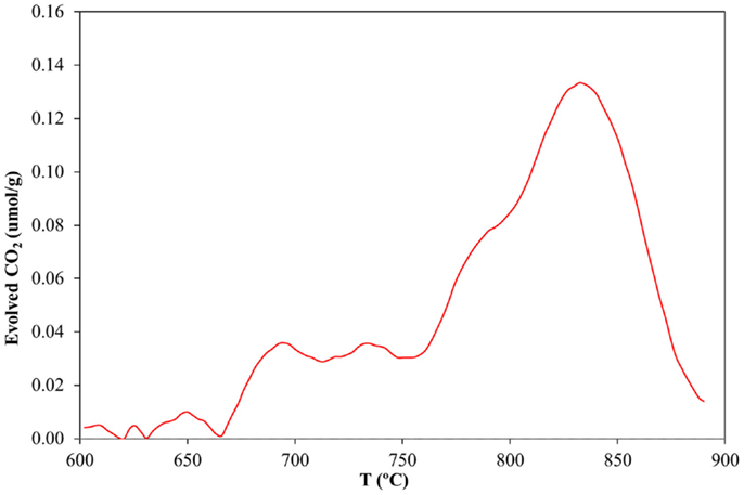
Figure 6. CO2 desorption rate profile as a function of temperature during the combustion of a CNT-loaded silica capillary tube described in this study in synthetic air.
The stability of the MWCNT coating on the silica wall was tested under hydrodynamic conditions. These preliminary tests consisted in flowing water aliquots through the MWCNT-modified capillary tubes at a controlled rate (0.1 mL s−1) corresponding to a linear velocity within the capillary of 2 m s−1. Each capillary segment was treated with approximately 103 times its inner volume. UV–Vis spectroscopic analysis of the water aliquots coming out of the treated capillary was employed in order to trace the possible leaching or washing-off of individual nanotubes or small bundles. The π-plasmon MWCNT characteristic signal centered at 245 nm was absent in all cases, suggesting that CNT concentration in the aliquot must fall below the detection limit of the technique, experimentally determined to be 10 ng mL−1. According to these results, we can establish that CNT leaching does not take place to a significant extent (<0.5% wt. of CNT considering the sensitivity of the spectrophotometer and the concentration of the starting MWCNT suspension).
Discussion
The main mechanism responsible for the stabilization of the CNTs in aqueous suspension is the ability of the surfactant employed in this study to favorably interact with the solvent. Given its structure (see Figure 1), the long hydrophobic chain and the aromatic ring will most likely interact with the CNT structure, leaving the acetamidine function exposed to the solvent. As described in Liu et al. (2006) and Fowler et al. (2012), depending on the pH the latter may become protonated (active) or deprotonated (inactive). In the former case, the active form involves an ionic species, which may interact with water, making the preparation of suspension of these polymer-protected MWCNTs possible, as illustrated in Figure 7. Thus, upon deprotonation of the active acetamidine function, the surfactant becomes neutral and the MWCNTs in the suspension bundle together to minimize their surface energy. These bundles are no longer stable and thus deposition occurs. As a result, the mechanism is very similar to the one we already reported for functionalized MWCNTs (Sanchís et al., 2014). It should be noted, however, that the procedure described in this manuscript does not require a lengthy or aggressive treatment for the carbon nanostructures. In addition, the amount of surfactant used is almost two orders of magnitude lower than other reports in which CNT suspensions were obtained by the use of surfactants (Bravo-Sanchez et al., 2010; García-Aguilar et al., 2014). Considering that the concentration of the resulting suspensions is comparable to those reported in the literature, our approach to employ a pH-switchable surfactant opens up new possibilities in the field on CNT inks and thin films preparation.
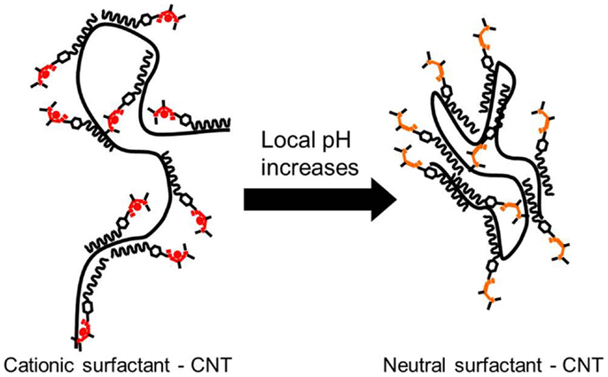
Figure 7. Schematic view of a MWCNT protected by DPDMA and its behavior depending on the pH of the solvent.
Concerning the deposition of the CNTs in the inner surface of silica capillaries, confinement of the electrochemically assisted deposition space enhances the local pH shift by favoring hydroxyl diffusion from the surface of the Pd wire (acting as cathode) toward the suspension contained within the capillary, limiting proton diffusion to the electrolyte reservoir (located at the bottom of the cell, see Figure 2). This change in the local pH inside the capillary causes the CNTs to coagulate as the DPDMA adopts its neutral form, favoring the massive deposition of the newly formed aggregates on the capillary surface. This phenomenon is also extended to the surface of the Pd wire. This was evidenced by the fact that removing the wire from the inside of the capillary through the septum resulted in the formation of a dark spot around the hole in the septum caused by the CNTs removal by attrition with the septum orifice. After 1 h of electrochemical treatment, the capillary tube inner wall was nearly covered with a homogeneous CNT coating along the length of the fused-silica capillary, as revealed by SEM images in Figure 5. Performing the deposition in cathodic conditions has the additional advantage that the deleterious formation of hydrogen peroxide, likely to happen during the oxidative decomposition of water, is avoided. Therefore, cathodic electrochemically assisted deposition is more conservative for the CNT integrity.
The TG analysis revealed that the amount of CNTs deposited on the inner surface of the capillary is enough to warrant a sufficiently functionalized silica surface (with its potential applicability in microreactor systems, for instance), with the added benefit that its cleaning may be easily done by flushing with an acidic aqueous solution, which could once again stabilize the DPDMA in its active form, making the MWCNTs water soluble again. To the best of our knowledge, this work pioneers the use of switchable surfactants to achieve an efficient dispersion of CNTs. In addition, the possibility to selectively induce aggregation of pristine CNTs in aqueous media and its utility in the generation of homogeneous deposits has been demonstrated for the first time. Furthermore, several important aspects concerning the electrodeposition method reported in this study should be highlighted: the thermal stability of the deposited CNTs, as compared to our previous study, has increased noticeably. Our result indicated that the MWCNTs functionalized using ammonium persulfate showed a burn-off temperature around 500°C (Sanchís et al., 2014), whereas those treated with DPDMA show a TG curve (see Figure 6) with an onset temperature above 650°C. This stability derives from the fact that the MWCNTs were not subjected to any chemical treatment, which might give rise to the appearance of defects on the CNTs surface, thus making them more reactive. The downside to this enhanced thermal stability is the fact that the resulting MWCNTs-DPDMA mixtures show poorer dispersability in water than the same MWCNTs treated with ammonium persulfate, as evidenced by the lower concentration of the resulting inks (0.3 vs. 0.9 mg mL−1). Finally, it is remarkable that despite using a more dilute CNT suspension, the amount of carbon species deposited on the inner surface of the capillary tube is threefold higher than that obtained when using a suspension of functionalized CNTs. This may be derived from the fact that the stability of DPDMA-coated MWCNTs is much more sensitive to the pH shift than in the case of functionalized CNT. This can be easily explained since in the former case there is just one kind of pH-sensitive functional group (acetamidine) with a well-defined pKa value instead of a random distribution of O-containing groups with different pKa values. Therefore, when the deposition on the silica surface takes place, large bundles and aggregates may be formed due to a highly synchronous destabilization mechanism.
To sum up, we have reported for the first time the use of a pH-switchable surfactant for the stabilization of CNTs in aqueous suspension and the use of the resulting inks in the application of MWCNTs deposits in the inner surface of fused-silica capillary tubes by electrochemically assisted deposition. The procedure is simple, reproducible, and has the advantage that the amounts of surfactant needed are very low, yielding good CNT dispersions. The coatings obtained are homogeneous, stable, and present a very good coverage, which make the resulting systems very promising candidates for their use in microreactor set-ups or as stationary phases for advanced chromatography applications and for preparing thin films on different shaped supports.
Conflict of Interest Statement
The authors declare that the research was conducted in the absence of any commercial or financial relationships that could be construed as a potential conflict of interest.
Acknowledgments
The authors gratefully acknowledge the funding from the Ministerio de Economía y Competitividad, Generalitat Valenciana, and FEDER (Projects CTQ2012-31762, MAT2013-42007-P, PrometeoII/2014/10, JCI-2012-12664, and RyC 2009-03913).
References
Berenguer-Murcia, Á, Cantoro, M., Golovko, V. B., Hofmann, S., Wirth, C. T., Johnson, B. F. G., et al. (2009). Stable colloidal Co–Pd nanocatalysts for carbon nanotube growth. Phys. Status Solidi B 246, 2436–2439. doi:10.1002/pssb.200982256
Bhandavat, R., Feldman, A., Cromer, C., Lehman, J., and Singh, G. (2013). Very high laser-damage threshold of polymer-derived Si(B)CN-carbon nanotube composite coatings. ACS Appl. Mater. Interfaces 5, 2354–2359. doi:10.1021/am302755x
Pubmed Abstract | Pubmed Full Text | CrossRef Full Text | Google Scholar
Boccaccini, A. R., Cho, J., Roether, J. A., Thomas, B. J. C., Jane Minay, E., and Shaffer, M. S. P. (2006). Electrophoretic deposition of carbon nanotubes. Carbon 44, 3149–3160. doi:10.1016/j.carbon.2006.06.021
Bravo-Sanchez, M., Simmons, T. J., and Vidal, M. A. (2010). Liquid crystal behavior of single wall carbon nanotubes. Carbon 48, 3531–3542. doi:10.1016/j.carbon.2010.05.051
de Mello, A. J. (2006). Control and detection of chemical reactions in microfluidic systems. Nature 442, 394–402. doi:10.1038/nature05062
Pubmed Abstract | Pubmed Full Text | CrossRef Full Text | Google Scholar
Domínguez-Domínguez, S., Berenguer-Murcia, Á, Pradhan, B. K., Linares-Solano, Á, and Cazorla-Amoros, D. (2008). Semihydrogenation of phenylacetylene catalyzed by palladium nanoparticles supported on carbon materials. J. Phys. Chem. C 112, 3827–3834. doi:10.1021/jp710693u
Fowler, C. I., Jessop, P. G., and Cunningham, M. F. (2012). Aryl amidine and tertiary amine switchable surfactants and their application in the emulsion polymerization of methyl methacrylate. Macromolecules 45, 2955–2962. doi:10.1021/ma2027484
Franklin, N. R., and Dai, H. (2000). An enhanced CVD approach to extensive nanotube networks with directionality. Adv. Mater. 12, 890–894. doi:10.1002/1521-4095
Gábor, T., Aranyi, D., Papp, K., Kármán, F. H., and Kálmán, E. (2007). Dispersibility of carbon nanotubes. Mat. Sci. Forum 537-538, 161–168. doi:10.4028/www.scientific.net/MSF.537-538.161
Gao, B., Yue, G. Z., Qiu, Q., Cheng, Y., Shimoda, H., Fleming, L., et al. (2001). Fabrication and electron field emission properties of carbon nanotube films by electrophoretic deposition. Adv. Mater. 13, 1770–1773. doi:10.1002/1521-4095
García-Aguilar, J., Miguel-García, I., Berenguer-Murcia, Á, and Cazorla-Amorós, D. (2014). Single wall carbon nanotubes loaded with Pd and NiPd nanoparticles for H2 sensing at room temperature. Carbon 66, 599–611. doi:10.1016/j.carbon.2013.09.047
Hartman, R. L., and Jensen, K. F. (2009). Microchemical systems for continuous-flow synthesis. Lab Chip 9, 2495–2507. doi:10.1039/B906343A
Pubmed Abstract | Pubmed Full Text | CrossRef Full Text | Google Scholar
Hartman, R. L., McMullen, J. P., and Jensen, K. F. (2011). Deciding whether to go with the flow: evaluating the merits of flow reactors for synthesis. Angew. Chem. Int. Ed. 50, 7502–7519. doi:10.1002/anie.201004637
Pubmed Abstract | Pubmed Full Text | CrossRef Full Text | Google Scholar
Hessel, V., Kralisch, D., Kockmann, N., Noël, T., and Wang, Q. (2013). Novel process windows for enabling, speeding-up and uplifting chemistry. ChemSusChem 6, 746–789. doi:10.1002/cssc.201200766
Pubmed Abstract | Pubmed Full Text | CrossRef Full Text | Google Scholar
Kumar, M., and Ando, Y. (2010). Chemical vapor deposition of carbon nanotubes: a review on growth mechanism and mass production. J. Nanosci. Nanotechnol. 10, 3739–3758. doi:10.1166/jnn.2010.2939
Pubmed Abstract | Pubmed Full Text | CrossRef Full Text | Google Scholar
Lee, S. W., Kim, B. S., Chen, S., Shao-Horn, Y., and Hammond, P. T. (2009). Layer-by-layer assembly of all carbon nanotube ultrathin films for electrochemical applications. J. Am. Chem. Soc. 131, 671–679. doi:10.1021/ja807059k
Pubmed Abstract | Pubmed Full Text | CrossRef Full Text | Google Scholar
Liu, Y., Jessop, P. G., Cunningham, M., Eckert, C. A., and Liotta, C. L. (2006). Switchable surfactants. Science 313, 958–960. doi:10.1126/science.1128142
Pubmed Abstract | Pubmed Full Text | CrossRef Full Text | Google Scholar
Mogensen, K. B., and Kutter, J. P. (2012). Carbon nanotube based stationary phases for microchip chromatography. Lab Chip 12, 1951–1958. doi:10.1039/c2lc40102a
Pubmed Abstract | Pubmed Full Text | CrossRef Full Text | Google Scholar
Padmarj, D., Zagozdzon-Wosik, W., Xie, L. M., Hadjiev, V. G., Cheruki, P., and Wosik, J. (2009). Parallel and orthogonal E-field alignment of single-walled carbon nanotubes by AC dielectrophoresis. Nanotechnology 20, 035201. doi:10.1088/0957-4484/20/3/035201
Pubmed Abstract | Pubmed Full Text | CrossRef Full Text | Google Scholar
Papper, V., Gorgy, K., Elouarzaki, K., Sukharaharja, A., Cosnier, S., and Marks, R. S. (2013). Biofunctionalization of multiwalled carbon nanotubes by irradiation of electropolymerized poly(pyrrole–diazirine) films. Chemistry 19, 9639–9643. doi:10.1002/chem.201300873
Pubmed Abstract | Pubmed Full Text | CrossRef Full Text | Google Scholar
Peterson, D. S. (2005). Solid supports for micro analytical systems. Lab Chip 5, 132–139. doi:10.1039/B405311G
Pubmed Abstract | Pubmed Full Text | CrossRef Full Text | Google Scholar
Sanchís, C., Berenguer-Murcia, Á, Ruiz-Rosas, R., Morallón, E., and Cazorla-Amorós, D. (2014). Preparation of homogeneous CNT coatings in insulating capillary tubes by an innovative electrochemically-assisted method. Carbon 67, 564–571. doi:10.1016/j.carbon.2013.10.029
Sujith Kumar, C. S., Suresh, S., Yang, L., Yang, Q., and Aravind, S. (2014). Flow boiling heat transfer enhancement using carbon nanotube coatings. Appl. Therm. Eng. 65, 166–175. doi:10.1016/j.applthermaleng.2013.12.053
Thomas, B. J. C., Boccaccini, A. R., and Shaffer, M. S. P. (2005). Multi-walled carbon nanotube coatings using electrophoretic deposition (EPD). J. Am. Ceram. Soc. 88, 980–982. doi:10.1111/j.1551-2916.2005.00155.x
Pubmed Abstract | Pubmed Full Text | CrossRef Full Text | Google Scholar
Whitesides, G. M. (2006). The origins and the future of microfluidics. Nature 442, 368–373. doi:10.1038/nature05058
Pubmed Abstract | Pubmed Full Text | CrossRef Full Text | Google Scholar
Xiang, C., Lu, W., Zhu, Y., Sun, Z., Yan, Z., Hwang, C.-C., et al. (2012). Carbon nanotube and graphene nanoribbon-coated conductive kevlar fibers. ACS Appl. Mater. Interfaces 4, 131–136. doi:10.1021/am201153b
Pubmed Abstract | Pubmed Full Text | CrossRef Full Text | Google Scholar
Keywords: carbon nanotubes, coatings, pH-switchable polymer, silica capillaries, microreactors
Citation: Sanchís C, Ruiz-Rosas R, Berenguer-Murcia Á, Morallón E and Cazorla-Amorós D (2015) Switchable surfactant-assisted carbon nanotube coatings: innovation through pH shift. Front. Mater. 2:1. doi: 10.3389/fmats.2015.00001
Received: 05 November 2014; Paper pending published: 06 December 2014;
Accepted: 05 January 2015; Published online: 26 January 2015.
Edited by:
Tomás Cordero, Universidad de Málaga, SpainReviewed by:
Thiagarajan Soundappan, Washington University in St. Louis, USANoriko Yoshizawa, National Institute of Advanced Industrial Science and Technology, Japan
Yoshiaki Matsuo, University of Hyogo, Japan
Copyright: © 2015 Sanchís, Ruiz-Rosas, Berenguer-Murcia, Morallón and Cazorla-Amorós. This is an open-access article distributed under the terms of the Creative Commons Attribution License (CC BY). The use, distribution or reproduction in other forums is permitted, provided the original author(s) or licensor are credited and that the original publication in this journal is cited, in accordance with accepted academic practice. No use, distribution or reproduction is permitted which does not comply with these terms.
*Correspondence: Diego Cazorla-Amorós, Departamento de Química Inorgánica e Instituto Universitario de Materiales, University of Alicante, P.O. Box 99, San Vicente del Raspeig E-03080, Alicante, Spain e-mail: cazorla@ua.es