Stretchable conductive networks of carbon nanotubes using plasticized colloidal templates
 Patnarin Worajittiphon
 Matthew J. Large
 Alice A. K. King
 Izabela Jurewicz
 Alan Brian Dalton
- 1Department of Chemistry, Faculty of Science, Chiang Mai University, Chiang Mai, Thailand
- 2Department of Physics, University of Surrey, Guildford, UK
We present a study of the behavior of highly ordered, segregated single-wall carbon nanotube (CNT) networks under applied strain. Polymer latex templates induce self-assembly of CNTs into hexagonal (2D) and honeycomb (3D) networks within the matrix. Using mechanical and spectroscopic analysis, we have studied the strain transfer mechanisms between the CNT network and the polymer matrix. Axial deformation of the nanotube network under applied strain is indicated by downshifts in the 2D mode in the Raman spectra, as well as variation in the radial breathing modes. The slippage within nanotube bundles at high strain is indicated by a reduction in the 2D mode rate of change. The fractional resistance change of the composites with strain obeys power law dependence. We present a model for the behavior of CNT bundles under strain informed by these measurements, and potential applications for such composite materials in elastic electronic devices that can tolerate high strain.
Introduction
We are living in an electronics age, in which the constantly evolving requirement for materials’ properties places enormous demands on research and development. The drive for flexible electronics is a particular area undergoing rapid development, the exploitation of nanoparticle properties within elastic polymer matrices potentially allows for transparency, flexibility, and optimal electronic control. Applications such as flexible displays, organic light-emitting diodes (OLEDs), photovoltaics (PVs), robust interconnects, and wearable electronics all demand the maintenance of conductivity while undergoing deformation over multiple cycles.
Earlier work on nanoparticle–polymer composites has made use of multiple fabrication concepts, with the nanoparticle junctions usually acting as the failure sites. Methods to improve the nanoparticle incorporation are critical to improving the functionality of stretchable composites for electronics. Techniques have included “welded” or supported junctions (Lee et al., 2013; Chen and Liao, 2014), or the use of multiple interfaces, such as the use of carbon nanotube (CNT) forests (Chun et al., 2010), or the improvement of interfacial adhesions between the matrix and the nanoparticle (Li et al., 2014). CNTs are particularly attractive as functional filler materials, and their inclusion into flexible composites has been studied extensively. However, large filler fractions, which reduce transparency, are required for the best conductivities unless an organized network can be formed that makes use of the large CNT aspect ratio, thereby maintaining conductivity while reducing opacity (Ponnamma et al., 2014). So far, there have been two approaches to this. The first, through the use of pre-stretching to produce alignment within the composite (Lin et al., 2013), but the stretching can therefore only be performed in one direction and conductivity is only maintained in that uniaxial direction. The second approach is to use self-assembly of the CNT network within the polymer matrix. The use of chemical vapor deposition (CVD) grown CNT forests is a popular choice as they are already highly aligned (Shin et al., 2014); however, this presents the same one dimensionality. The use of patterning can also produce a network of CNTs. It has been shown recently that the use of a radial pattern can give improved results (Grilli et al., 2014); however, the self-assembly of CNTs to form a segregated network in two or three dimensions is still highly prized.
Templated self-assembly of single-wall carbon nanotubes (SWNTs) into low-percolation conductive films has been demonstrated previously (Kim et al., 2008; Jurewicz et al., 2010, 2011, 2012; Worajittiphon et al., 2010). This technique reduces the filler weight fraction required to form percolating conductive pathways by exclusion from the latex polymer volume during initial film formation. The advantages in terms of industrial processing therefore include cost reduction compared to random composites [which have a necessarily higher percolation threshold (Jurewicz et al., 2011)], and the ability to perform liquid processing, such as spray coating and inkjet printing.
Here, we evaluate the behavior of ordered 2D hexagonal and 3D honeycomb SWNT networks – formed by templated assembly – under large applied strains. We utilize Raman spectroscopy to probe the microscopic deformation of SWNTs in bulk composites under macroscopic strains giving us useful insights into strain transfer in SWNT composite materials. The results indicate that such composite structures may have viable applications as stretchable conductors whereby the nanotubes remain percolating even under large applied strain. This effect is fundamentally different to traditional polymer nanotube composites where applying large strain normally has an irreversible deleterious effect on electrical conductivity.
Materials and Methods
Materials
Latex
The emulsion polymerized latex (NeoResins, The Netherlands) used in this work was a random copolymer consisting of butyl acrylate (BA), methyl methacrylate (MMA), methacrylic acid (MAA), and acetoacetoxyethyl methacrylate (AAEM) with the molar ratio of 36.7:50.3:3:10, respectively.
CNT dispersion
High pressure carbon monoxide (HiPco) synthesized SWNTs (Unidym Inc., CA, USA) were used to prepare SWNT dispersions, the SWNTs have diameters between 0.8 and 1.2 nm and lengths ranging from 100 to 1000 nm. The nanotubes were dispersed in a non-ionic surfactant solution containing Triton X-100 (Union Carbide Corp., TX, USA) and deionized (DI) water, at a Triton X-100 concentration of 10 mg mL−1. The as-received SWNT powder was added to the surfactant solution to produce a 1 mg mL−1 final concentration of SWNTs; dispersion of the powder was achieved using tip sonication (Branson Sonifier 150, Branson Ultrasonics Corp., Danbury, CT, USA) for 10 min at an output power of 20 W in an ice bath.
Composite dispersion
The prepared SWNT dispersion was blended with the as-received latex dispersion by tip sonication at 10 W for 10 min in an ice bath to obtain a composite dispersion.
Sample Preparation
In order to produce free-standing monolayer samples for mechanical testing, a thick substrate film consisting of pure latex was prepared; this was done to achieve good mechanical matching.
Latex substrate preparation
The latex suspension used was first mixed by hand with an aqueous solution of Triton X-100 (an equivalent volume of the same concentration used to disperse the SWNTs). This was to ensure that the mechanical properties of the substrate and composite monolayer film were as closely matched as possible. The latex was then cast in a polytetrafluoroethylene (PTFE) trough and allowed to dry completely at ambient temperature (22°C).
Coating composite monolayers on latex substrate
To produce monolayer coatings the composite SWNT-latex dispersion was spin coated onto the prepared latex substrates at 2000 rpm for 10 s at room temperature (22°C). The resulting two-layer film was cut into strips measuring ~2.5 mm × 20 mm × 0.4 mm. The number of layers was confirmed using AFM.
Strained samples
After spin coating, the cut samples were strained with a tensile load using a texture analyzer (MicroSystems Texture Analyzer, Godalming, UK). When the desired strain was achieved, the sample was fixed to a metal stub using an adhesive tape; to prevent relaxation the ends were cut and fixed at the back of the stub. This was done to allow AFM investigation of the strained material.
Bulk composite films
The production of free-standing composite films was performed using a similar technique to the latex substrates for the monolayer films; composite dispersions (1 and 0.2 wt% SWNT in latex) were cast in PTFE troughs and dried in ambient conditions. The resulting films were cut into pieces (with approximate dimensions 5 mm × 26 mm × 0.17 mm), and electrodes were added to both ends of each sample using a solvent-based colloidal silver paint (G3790, Agar Scientific) for conductivity measurements.
Analysis
Atomic force microscopy (AFM) was performed in intermittent contact (AM) mode (NT-MDT, Moscow, Russia). Gold cantilevers with force constants of 1.45–15.1 Nm−1 and resonant frequencies in the range 87–230 kHz were used. The degree of ordering in the composite monolayer was ascertained using a fast Fourier transform (FFT) analysis in software. A Hitachi S-4000 field emission scanning electron microscope was used to take SEM images at an accelerating voltage of 4–6 kV; no coating was applied. Raman measurements were obtained using the 473 nm excitation wavelength of an NTEGRA Raman microscope (NT-MDT, Moscow, Russia) equipped with a 100× objective lens.
Stress–strain curves for the latex substrates were obtained using a MicroSystems Texture Analyzer (Godalming, UK); curves for the bulk SWCNT/latex composite films were obtained using a Linkam TST350 tensile testing stage (Guildford, UK). Electrical conductivity of the film samples was measured using a Keithley 2400 Source-meter.
Results and Discussion
From our previous work on stretchable composites based on CNTs assembled in the interstitial sites of the polymer latex matrix, we learned that the electrical percolation threshold for a composite with a segregated microstructure is as low 0.12 wt.% (Jurewicz et al., 2010, 2011). For such a composite material to maintain its desirable properties under deformation, network connectivity must be maintained. Near the percolation threshold, there will be a small number of conducting paths in a composite and it is reasonable to expect a very large change in conductivity under deformation as the small number of interconnects are broken. Therefore, if we want to exploit such composites for high strain applications, it is necessary to use SWNT concentrations significantly above the percolation threshold where the conductive network is fully developed (Jurewicz et al., 2011). This allows the formation of complete, continuous networks whose transport properties should be more resilient under deformation. Therefore, for this work, we have chosen two composites containing either 0.2, 0.5, or 1 wt.% of SWNTs in the final dry samples. For SWNT-latex composite films in this concentration regime, we expect to see SWNT bundles forming complete networks within the latex crystal template well above the electrical percolation threshold (Jurewicz et al., 2010). Moreover, at large strain levels, these composites maintain their viscoelastic properties and still conduct electricity.
Understanding the Stress Transfer between CNT Bundles Locked in the Colloidal Lattice Under Large Applied Strains
In order to understand the stress transfer occurring between the individual CNT bundles locked in the colloidal matrix under high strain, a thin composite monolayer film is spin coated onto a substrate fabricated from the same polymer latex as the one used for producing the composite materials in order to minimize the effect of yield strength mismatch at the associated interface. This is to ensure that when the sample is stretched, both the substrate and the composite monolayer follow the same stress–strain relationship.
The non-ionic surfactant Triton X-100 is used to initially disperse CNTs in water, before incorporating the dispersion into the polymer latex as it acts as a plasticizer and reduces the polymer’s glass transition temperature (Jurewicz et al., 2012). The plasticization has a substantial effect on the mechanical properties of the composite, increasing its yield strain.
Latex substrates were prepared using an equivalent amount of Triton X-100 surfactant to the 0.5 and 1 wt.% composite dispersions. Figure 1A shows the respective stress–strain curves to failure. It is evident from the stress–strain curves in Figure 1A that the film with more surfactant (1 wt.% equivalent SWNT concentration) exhibits a lower toughness and a higher strain at failure; this indicates greater plasticization of the latex polymer by the surfactant. In subsequent tests on the composite monolayers, the maximum applied strain was chosen to respect the limits of the substrate. Figures 1B,C show AFM height and phase images of the polymer substrate, illustrating domains with a high degree of hexagonal order, further illustrated by the sixfold symmetry associated with the inset FFT in Figure 1B.
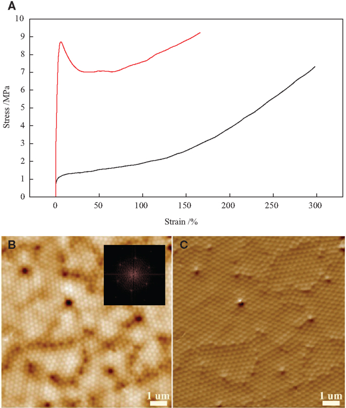
Figure 1. (A) Stress–strain behaviors of the latex substrates made using an equivalent concentration of Triton X-100 as those used in 0.5 wt%  and 1 wt.% ( – ) SWNT/latex monolayers. (B,C) AFM height and phase (respectively) of a Triton X-100/latex substrate containing an equivalent concentration of Triton X-100 as used in 1 wt.% SWNT/latex film. Inset is an FFT analysis of an area of (B), illustrating the strong hexagonal symmetry of the local particle packing.
Figure 2A shows an SEM image of a spin coated 1 wt.% SWNT/latex monolayer on top of the substrate described above. Clearly visible is the segregated SWNT network formed (2D hexagonal arrangement) in the latex crystal interstices during drying. Figures 2B–E show AFM phase images of the same composite monolayer strained at 0, 100, 150, and 250%, respectively. We can see that strong polymer ordering is maintained at high strains, with approximately uniform deformation of the constituent latex spheres.
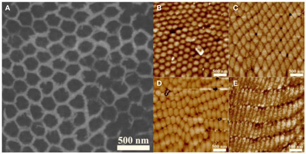
Figure 2. (A) SEM micrograph of an unstrained 1 wt.% SWNT composite monolayer. (B–E) AFM phase images of a 1 wt.% SWNT composite monolayer strained at 0, 100, 150, and 250%, respectively. The drawing direction is approximately vertical in these images, and it can be seen that the latex particles deform along the same axis.
In order to analyze the microstructure, before and after strain, we use a combination of SEM and AFM. The SEM micrograph of an unstrained composite film shown in Figure 2A reveals that nanotubes order in a honeycomb-like arrangement templated by the surrounding polymer colloidal close-packed assembly. The resulting network of CNT bundles is continuous in the plane of the film. AFM reveals that there is a strong correlation between applied strain and changes in film morphology. It is apparent that the polymer particles undergo deformation, becoming more elongated in the direction of applied stress (Figures 2B–E). In previous work, we have shown qualitatively that for 3D composites, there is a resulting mapping of the nanotube assembly with polymer deformation (Jurewicz et al., 2010).
Raman spectroscopy is a powerful tool for probing the microscopic deformation of SWNTs in bulk composites under macroscopic strains (Frogley et al., 2002; Rowell and McGehee, 2011). When under strain the inter-carbon bond distance of a CNT is changed; this results in shifts in wavenumber of the 2D-band peak (Frogley et al., 2002) as well as the radial breathing mode (RBM) peak (Li et al., 2013) of the CNT Raman spectrum. As such, Raman spectroscopy can give useful insights into strain transfer in SWNT composite materials (Levshov et al., 2010; Li et al., 2013).
The shift of the 2D-band (a.k.a. the G′-band; the disorder-induced second order mode) peak is used to monitor load transfer between the latex template and the SWNT networks, as has been demonstrated elsewhere (Rowell and McGehee, 2011). The averaged wavenumber of the 2D peak (three measurements per sample) are plotted against sample strain in Figure 3A for both the 0.5 and 1 wt.% SWNT composite monolayers. Included for comparison are the 2D positions for samples allowed to fully relax after being drawn beyond failure (referred to as “broken” samples). The unstrained wavenumber for this band is seen to be near 2680 cm−1; this is in very good agreement with the value for as-prepared SWNT samples in the review by Eklund et al. (1995). The results for both samples clearly indicate two different modes of deformation for the CNT bundles; the shift is linear up to ~100% sample strain, above which the gradient of the linear fit is reduced. This indicates that beyond 100% sample strain, the transfer of strain between the matrix and the individual nanotubes is reduced, suggesting slippage within the nanotube bundles (Lucas and Young, 2004).
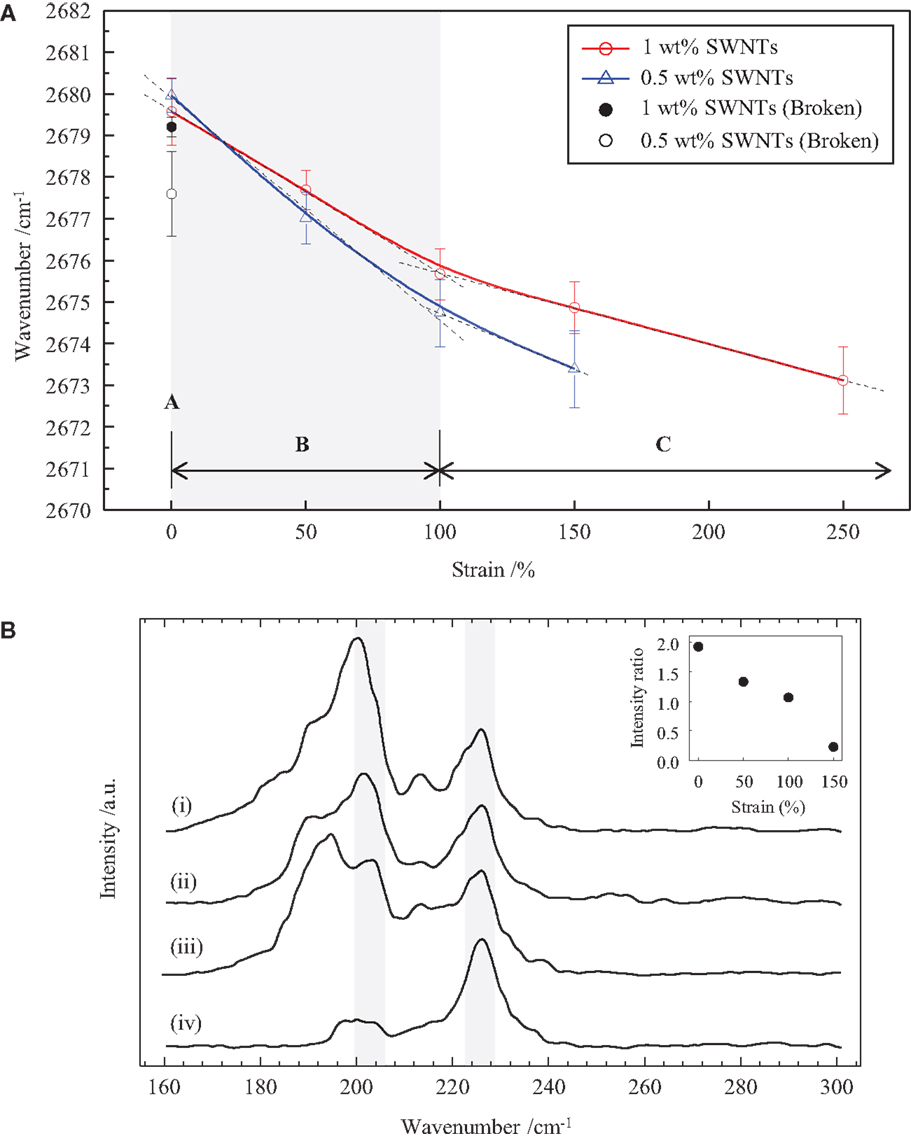
Figure 3. (A) Averaged 2D wavenumber as a function of strain for 0.5 and 1 wt.% SWNT samples, taken from Raman measurements. Two different strain regimes (B and C) are visible, which are characterized by different linear dependences of the D*-band wavenumber. (B) Raman spectra of the radial breathing mode (RBM) for the 1 wt% SWNT sample as a function of strain; (i) 0%, (ii) 50%, (iii) 100%, and (iv) 150%. Inset shows the Raman intensity ratio of the RBM peaks at 201 and 227 cm−1.
Figure 3B shows spectra for the RBM peaks of the 1 wt.% SWNT sample under applied strains up to 150%. Inset is a plot of intensity ratio of the RBM peaks at 201 and 227 cm−1 against strain, showing a decreasing trend. It is established that the RBM peak at 201 cm−1 is largely the result of strong van der Waals interactions between nanotubes (Rao et al., 2001). As a result, we can conclude that the change in intensity ratio may be due either to separation of the tubes in the bundle or a reduction in contact area by slipping of adjacent tubes. It has also been shown however, that the intensity change can be a result of changes in the Van Hove singularities due to the applied strain, which varies the resonance of the RBM modes, and so the intensity can change. The changes are defined by the structure of the CNT being probed (Lucas and Young, 2004).
Figure 4 shows polarized Raman spectra for the 1 wt.% SWNT composite monolayer strained to 150%, as a function of the angle subtended by the drawing and polarization directions (θ). Inset shows the averaged normalized intensities of all peaks in Figure 4. It is established from the study of aligned 1D materials that the Raman intensity should fall away in proportion to cos4θ (Hwang et al., 2000). The inset data compare favorably, indicating a high degree of alignment of the embedded SWNTs along the drawing direction. As such we can expect that the nanotube bundles are generally under compressive stresses from the matrix in the transverse directions. Combined with the RBM data, we can conclude that the strain is inducing variation in the band gap of the SWNTs, as well as the possibility of slippage within the SWNT bundles.
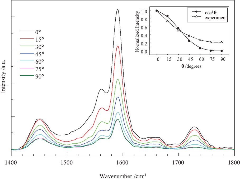
Figure 4. Polarized Raman spectra of a 150%-strained 1 wt.% SWNT/latex monolayer as the polarization direction and specimen-drawing direction subtend an angle, θ, of 0° (parallel), 15°
 , 30°
, 30° , 45°
, 45° , 60°
, 60° , 75°
, 75° , and 90°
 (perpendicular). Inset shows the averaged normalized Raman intensity of all peaks in (a) as the angle θ varies. This data indicates a high degree of alignment of the nanotubes along the drawing direction.
It has been well established that there is a low strain and a high strain regime for CNT composites. The 2D position decreases linearly with increasing strain at low strain, and at high strain the trend is the same but with a much lower gradient (Frogley et al., 2002; Lucas and Young, 2004). It is possible that in some cases this is due to structural changes occurring in the matrix; however, it appears to be a generalized trend for all CNT composites. It is likely that due to slippage within the CNT bundles the transfer of strain to the individual CNTs is reduced. The bundle size and distribution will also then affect the amount of strain transfer and slippage, which gives rise to the variation in the rates of Raman shift change with strain observed in the literature.
Characterization of Bulk Composite Films
To investigate the behavior of the bulk composite films, measurements of the stress–strain curve and resistance of each sample were performed concurrently. A bias voltage of 20 V was applied to the sample electrodes, and the current measured as the samples were strained. Figure 5A shows the resistance–strain curves (to failure) of two samples; one with 1 wt.% SWNT, the other with 0.2 wt.% SWNT. The 0.2 wt.% sample has a CNT inclusion close to the percolation threshold for these systems (Jurewicz et al., 2011), and was studied to investigate the difference in behavior between dense bundled networks and sparse networks where the population of unbundled CNTs is likely to be higher (Feng and Jiang, 2014). Figure 5B shows the fractional resistance change (ΔR/R0) against strain. The dashed line represents a power law relation, which can be seen to fit the data for both samples very well over the whole strain range.
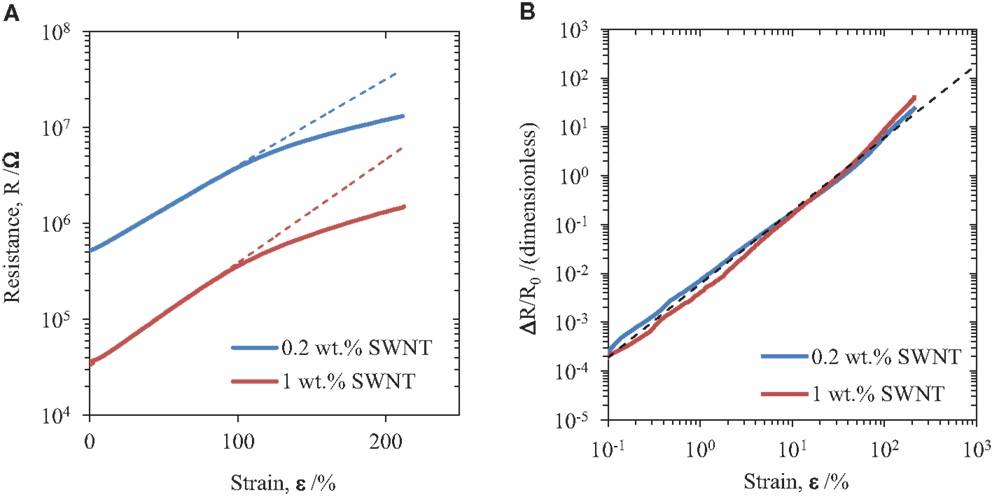
Figure 5. (A) Resistance–strain curves for two bulk SWCNT-latex composite films. The dashed lines represent the exponential behavior R = R0exp(γε) with γ = 2.07 for the 0.2 wt.% SWNT sample and γ = 2.48 for the 1 wt.% SWNT sample. Note that the region where the data appears to follow this trend is the same for highly bundled systems (1 wt.% SWNT) and systems just above the percolation threshold (0.2 wt.% SWNT). (B) Plots of fractional resistance change (ΔR/R0) against strain. The dashed line suggests that the behavior is better represented by a power law (Cεn) with exponent n ~ 1.5.
We see that the gage factor (G), which is the constant of proportionality between ΔR/R0 and strain, can be identified with the gradient of the curve ΔR/R0. Based on the power law evident from Figure 5B, this will also have power law dependence with exponent ~0.5. In addition, both samples with 0.2 and 1 wt.% SWNTs offer a resistance difference about one order of magnitude over the whole range of tensile strain (up to about 200% strain) applied in this study for each of them. Based on such a strain-dependent behavior of the electrical resistance, the polymer composites fabricated using latex technology could be an effective candidate for advanced materials used for mechanical strain sensors.
Conclusion
We have presented a study of conducting CNT networks – formed by templated assembly within a latex polymer matrix – under applied macroscopic strain. Evidence from Raman studies of CNTs in composite monolayers suggest that strain is transferred from the matrix to the CNT bundles, and is divided between axial strain on the nanotubes and slippage of nanotubes within the bundles. Downshift of the 2D peak position is indicative of axial strain on the individual tubes, while the change in intensity ratio of the RBM peaks at 201 and 227 cm−1 can be attributed to reduction in contact area between CNTs as the bundles are strained as well as strain induced changes in the CNT Van Hove singularities giving rise to different resonance conditions.
Bulk SWNT/latex composite films were prepared, and their strain-dependent electrical properties studied. We find that their fractional resistance change behavior does not alter significantly with SWNT inclusion between 0.2 and 1 wt.%, and it is well described by a power law expression with exponent ~1.5. This suggests that the gage factor (G) (which relates the proportionality of sample resistance to strain) is a function of strain with approximate dependence (G ∝ √ε). Although this means that such composites are not useful as tensile sensors for very small strain, their properties should be robust under bending and therefore find use as interconnect materials in flexible organic electronic devices, owing to the elastic nature of the matrix material. Such polymeric composites, however, are promising for use as materials for mechanical sensors, due to significant resistance variation over a large strain range.
Conflict of Interest Statement
The authors declare that the research was conducted in the absence of any commercial or financial relationships that could be construed as a potential conflict of interest.
Acknowledgments
This work was supported by EPSRC. We thank NeoResins for supplying the latex dispersion. The authors would like to acknowledge the Royal Thai Government for financial support. We also thank Mrs. Violeta Doukova for general laboratory assistance.
References
Chen, S. P., and Liao, Y. C. (2014). Highly stretchable and conductive silver nanowire thin films formed by soldering nanomesh junctions. Phys. Chem. Chem. Phys. 16, 19856–19860. doi: 10.1039/c4cp02808b
Pubmed Abstract | Pubmed Full Text | CrossRef Full Text | Google Scholar
Chun, K. Y., Oh, Y., Rho, J., Ahn, J. H., Kim, Y. J., Choi, H. R., et al. (2010). Highly conductive, printable and stretchable composite films of carbon nanotubes and silver. Nat. Nanotechnol. 5, 853–857. doi:10.1038/nnano.2010.232
Pubmed Abstract | Pubmed Full Text | CrossRef Full Text | Google Scholar
Eklund, P. C., Holden, J. M., and Jishi, R. A. (1995). Vibrational-modes of carbon nanotubes – spectroscopy and theory. Carbon N. Y. 33, 959–972. doi:10.1016/0008-6223(95)00035-C
Feng, C., and Jiang, L. Y. (2014). Investigation of uniaxial stretching effects on the electrical conductivity of CNT-polymer nanocomposites. J. Phys. D Appl. Phys. 47, 405103. doi:10.1088/0022-3727/47/40/405103
Frogley, M. D., Zhao, Q., and Wagner, H. D. (2002). Polarized resonance Raman spectroscopy of single-wall carbon nanotubes within a polymer under strain. Phys. Rev. B 65, 113413. doi:10.1103/PhysRevB.65.113413
Grilli, S., Coppola, S., Vespini, V., Pagliarulo, V., Nasti, G., Carfagna, C., et al. (2014). One-step fabrication of free-standing flexible membranes reinforced with self-assembled arrays of carbon nanotubes. Appl. Phys. Lett. 105, 153101. doi:10.1063/1.4898206
Hwang, J., Gommans, H. H., Ugawa, A., Tashiro, H., Haggenmueller, R., Winey, K. I., et al. (2000). Polarized spectroscopy of aligned single-wall carbon nanotubes. Phys. Rev. B 62, 13310–13313. doi:10.1103/PhysRevB.62.R13310
Jurewicz, I., Keddie, J. L., and Dalton, A. B. (2012). Importance of capillary forces in the assembly of carbon nanotubes in a polymer colloid lattice. Langmuir 28, 8266–8274. doi:10.1021/la301296u
Pubmed Abstract | Pubmed Full Text | CrossRef Full Text | Google Scholar
Jurewicz, I., King, A. A., Worajittiphon, P., Asanithi, P., Brunner, E. W., Sear, R. P., et al. (2010). Colloid-assisted self-assembly of robust, three-dimensional networks of carbon nanotubes over large areas. Macromol. Rapid Commun. 10, 609–615. doi:10.1002/marc.200900799
Pubmed Abstract | Pubmed Full Text | CrossRef Full Text | Google Scholar
Jurewicz, I., Worajittiphon, P., King, A. A., Sellin, P. J., Keddie, J. L., and Dalton, A. B. (2011). Locking carbon nanotubes in confined lattice geometries – a route to low percolation in conducting composites. J. Phys. Chem. B 115, 6395–6400. doi:10.1021/jp111998p
Pubmed Abstract | Pubmed Full Text | CrossRef Full Text | Google Scholar
Kim, M. H., Choi, J. Y., Choi, H. K., Yoon, S. M., Park, O. O., Yi, D. K., et al. (2008). Carbon nanotube network structuring using two-dimensional colloidal crystal templates. Adv. Mater. Weinheim 20, 457–461. doi:10.1002/adma.200700956
Lee, J., Lee, P., Lee, H. B., Hong, S., Lee, I., Yeo, J., et al. (2013). Room-temperature nanosoldering of a very long metal nanowire network by conducting-polymer-assisted joining for a flexible touch-panel application. Adv. Funct. Mater. 23, 4171–4176. doi:10.1002/adfm.201370168
Levshov, D. I., Yuzyuk, Y. I., Michel, T., Voisin, C., Alvarez, L., Berger, S., et al. (2010). Raman probing of uniaxial strain in individual single-wall carbon nanotubes in a composite material. J. Phys. Chem. C 114, 16210–16214. doi:10.1021/jp1040635
Li, J., Niu, Z., Zeng, Q., Cai, L., Zhang, X., Dong, H., et al. (2013). In-situ Raman spectra of single-walled carbon nanotube/epoxy nanocomposite film under strain. J. Nanosci. Nanotechnol. 13, 1145–1148. doi:10.1166/jnn.2013.6028
Pubmed Abstract | Pubmed Full Text | CrossRef Full Text | Google Scholar
Li, Q., Zaiser, M., Blackford, J. R., Jeffree, C., He, Y., and Koutsos, V. (2014). Mechanical properties and microstructure of single-wall carbon nanotube/elastomeric epoxy composites with block copolymers. Mater. Lett. 125, 116–119. doi:10.1016/j.matlet.2014.03.096
Lin, L., Fu, S., Zhang, S., Deng, H., and Fu, Q. (2013). Fabrication of highly stretchable conductors via morphological control of carbon nanotube network. Small 9, 1620–1629. doi:10.1002/smll.201202306
Pubmed Abstract | Pubmed Full Text | CrossRef Full Text | Google Scholar
Lucas, M., and Young, R. J. (2004). Raman spectroscopic study of the effect of strain on the radial breathing modes of carbon nanotubes in epoxy/SWNT composites. Compos. Sci. Technol. 64, 2297–2302. doi:10.1016/j.compscitech.2004.01.021
Ponnamma, D., Sadasivuni, K. K., Grohens, Y., Guo, Q., and Thomas, S. (2014). Carbon nanotube based elastomer composites-an approach towards multifunctional materials. J. Mater. Chem. C 2, 8446–8485. doi:10.1039/C4TC01037J
Rao, A. M., Chen, J., Richter, E., Schlecht, U., Eklund, P. C., Haddon, R. C., et al. (2001). Effect of van der Waals interactions on the Raman modes in single walled carbon nanotubes. Phys. Rev. Lett. 86, 3895–3898. doi:10.1103/PhysRevLett.86.3895
Pubmed Abstract | Pubmed Full Text | CrossRef Full Text | Google Scholar
Rowell, M. W., and McGehee, M. D. (2011). Transparent electrode requirements for thin film solar cell modules. Energy Environ. Sci. 4, 131–134. doi:10.1039/c0ee00373e
Shin, U.-H., Jeong, D.-W., Kim, S.-H., Lee, H. W., and Kim, J.-M. (2014). Elastomer-infiltrated vertically aligned carbon nanotube film-based wavy-configuration stretchable conductors. ACS Appl. Mater. Interfaces 6, 12909–12914. doi:10.1021/am502851e
Pubmed Abstract | Pubmed Full Text | CrossRef Full Text | Google Scholar
Worajittiphon, P., Jurewicz, I., King, A. A. K., Keddie, J. L., and Dalton, A. B. (2010). Enhanced thermal actuation in thin polymer films through particle nano-squeezing by carbon nanotube belts. Advanced Materials 22, 5310–5314. doi:10.1002/adma.201003145
Pubmed Abstract | Pubmed Full Text | CrossRef Full Text | Google Scholar
Keywords: carbon nanotubes, polymer latex, electrical conductivity, stretchable conductors, Raman spectroscopy
Citation: Worajittiphon P, Large MJ, King AAK, Jurewicz I and Dalton AB (2015) Stretchable conductive networks of carbon nanotubes using plasticized colloidal templates. Front. Mater. 2:15. doi: 10.3389/fmats.2015.00015
Received: 16 December 2014; Accepted: 09 February 2015;
Published online: 02 March 2015.
Edited by:
Ashok K. Sundramoorthy, University of Wisconsin-Madison, USAReviewed by:
Santosh Kumar Yadav, Drexel University, USAJianyuan Zhang, University of Washington, USA
Copyright: © 2015 Worajittiphon, Large, King, Jurewicz and Dalton. This is an open-access article distributed under the terms of the Creative Commons Attribution License (CC BY). The use, distribution or reproduction in other forums is permitted, provided the original author(s) or licensor are credited and that the original publication in this journal is cited, in accordance with accepted academic practice. No use, distribution or reproduction is permitted which does not comply with these terms.
*Correspondence: Izabela Jurewicz and Alan Brian Dalton, Department of Physics, University of Surrey, Stag Hill, Guildford GU2 7XH, UK e-mail: izabela.jurewicz@surrey.ac.uk; a.dalton@surrey.ac.uk