Ultrasonic assisted consolidation of commingled thermoplastic/glass fiber rovings
 Francesca Lionetto
 Riccardo Dell’Anna
 Francesco Montagna
  Alfonso Maffezzoli
- Materials Science and Technology Group, Department of Engineering for Innovation, University of Salento, Lecce, Italy
Thermoplastic matrix composites are finding new applications in different industrial area, thanks to their intrinsic advantages related to environmental compatibility and processability. The approach presented in this work consists in the development of a technology for the simultaneous deposition and consolidation of commingled thermoplastic rovings through to the application of high energy ultrasound. An experimental equipment, integrating both fiber impregnation and ply consolidation in a single process, has been designed and tested. It is made of an ultrasonic welder, whose titanium sonotrode is integrated on a filament winding machine. During winding, the commingled roving is at the same time in contact with the mandrel and the horn. The intermolecular friction generated by ultrasound is able to melt the thermoplastic matrix and impregnate the reinforcement fibers. The heat transfer phenomena occurring during the in situ consolidation have been simulated solving by finite element (FE) analysis, an energy balance accounting for the heat generated by ultrasonic waves and the melting characteristics of the matrix. To this aim, a calorimetric characterization of the thermoplastic matrix has been carried out to obtain the input parameters for the model. The FE analysis has enabled to predict the temperature distribution in the composite during heating and cooling. The simulation results have been validated by the measurement of the temperature evolution during ultrasonic consolidation. The reliability of the developed consolidation equipment has been proved by producing hoop wound cylinder prototypes using commingled continuous E-glass rovings and polypropylene filaments. The consolidated composite cylinders are characterized by high mechanical properties, with values comparable with the theoretical ones predicted by the micromechanical analysis.
Introduction
Continuous fiber reinforced thermoplastic matrix composites are showing a great potential for many different applications, thanks to their easy processing without requiring long curing times, their long shelf life, low level of moisture uptake, easy welding ability, and higher repairability potential (Ahmed et al., 2006; Sinmazcelik, 2006; Ning et al., 2007). Filament winding, widely used for the production of continuous fiber reinforced composites with thermosetting matrix, has been recently adopted for manufacturing continuous fiber reinforced thermoplastic materials (Henninger and Friedrich, 2002; Dobrzanski et al., 2007). The need of fast and efficient technologies has led to the development of simultaneous deposition and in situ consolidation of the commingled yarns or tapes with the application of heat in order to melt the thermoplastic matrix at the deposition interface. Several automated tape deposition techniques are available under the name of automated tape laying (ATL) or automated fiber placement (AFP) (Ye et al., 1995; Henninger et al., 2002; Gennaro et al., 2011; Mondo et al., 2012).
The heat sources currently used for on-line impregnation during filament winding are hot air jets or flames, which are characterized by an acceptable cost but also by a limited ability to control the temperature in narrow ranges, or laser sources, much easier to control but more expensive. In situ consolidation presents several critical aspects related to the temperature control, considering the high temperature needed for matrix melting. Additional issues occur when the deposition must take place on surfaces with single or double curvature with the need to orient the fibers in any arbitrary direction, obtaining at the same time a fully consolidated component (Tierney and Gillespie, 2006).
High energy ultrasound has a great potential for in situ composite consolidation. It can be easily automated for the deposition of thermoplastic matrix semi-pregs or prepregs, both on the flat and curved surfaces. More recently, it has been applied also to the joining and assembly of thermoplastic matrix composites (Liu et al., 2001; Yousefpour et al., 2004; Amancio-Filho and dos Santos, 2009; Fernandez Villegas and Bersee, 2010; Fernandez Villegas et al., 2013). Ultrasonic welding is also used during lay-up of thermoplastic tapes reinforced with carbon fibers to keep in place the different plies before full consolidation in autoclave.
In ultrasonic assisted consolidation, a sonotrode (or horn) transfers low amplitude (typically 5–100 μm) vibratory energy at high frequency (typically 20–40 kHz) to the joining parts. Vibrations are responsible of surface and intermolecular friction, which melt the thermoplastic matrix (Ávila-Orta et al., 2013). As observed by Tolunay et al. (1983), the heating occurs over the whole volume under the sonotrode tip. Ultrasonic consolidation of thermoplastic matrix composites does not require the use of any foreign material in the joint, such as the resistive inserts used for resistance welding (Ageorges and Ye, 2001; Ageorges et al., 2001).
In this work, high power ultrasound has been applied to the simultaneous deposition, impregnation, and consolidation of commingled thermoplastic rovings, made of thermoplastic filaments and glass fibers. An experimental set-up, integrating a laboratory filament winding machine with the sonotrode of an ultrasonic welding head, has been developed. The propagation of ultrasonic waves has been used to achieve melting of the thermoplastic matrix, impregnation of the reinforcement fibers and, finally, consolidation of the different plies of fiber reinforced thermoplastic composite materials. The system has the potential to consolidate layer by layer both flat and cylindrical samples with hoop windings. The heat transfer phenomena, which occurs during consolidation of thermoplastic rovings, have been simulated solving by finite element (FE) analysis, an energy balance accounting for the heat generated by ultrasonic waves and the melting characteristics of the matrix. A characterization of the physical and mechanical properties of samples obtained with this equipment has been performed.
Experimental
Materials
The material used in this study is a dry pseudo-prepreg, made by commingling continuous E-glass rovings and polypropylene (PP) filaments. It is supplied by Fiber Glass Industries Inc. under the trade name Twintex R PP 60 1870 N. The content of glass fibers is 60% by weight. A cross-section of the commingled roving is shown in Figure 1A. The ultrasonic horn, applying at the same time, ultrasonic waves and pressure, leads to the matrix melting and consolidation, as schematically sketched in Figure 1B.
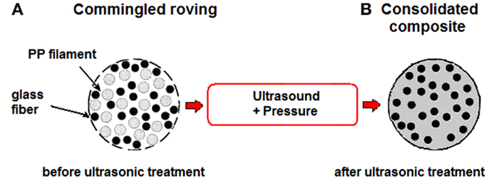
Figure 1. Sketch of the cross-section of commingled E-glass/PP roving (A) before and (B) after the ultrasonic consolidation treatment.
Ultrasonic Consolidation Equipment
The ultrasonic equipment developed in this study for the impregnation and in situ consolidation of commingled rovings is schematically represented in Figure 2. It integrates both fiber impregnation and ply consolidation in a single process. The equipment consists of an ultrasonic welder of thermoplastic polymers (Sonic Italia, s.r.l.), characterized by a maximum power of 2000 W and a frequency of 20 kHz, whose titanium sonotrode is mounted on a filament winding machine (VEM S.p.a.). This latter is a 2 degree of freedom machine equipped with a mandrel of 150 mm diameter.
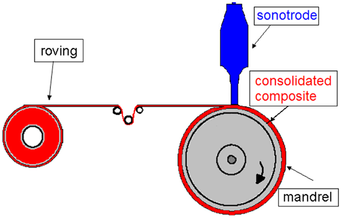
Figure 2. Schematic representation of the equipment developed for the ultrasonic consolidation during filament winding.
The commingled roving, after being tensioned by a tension controller, is wound on a rotating mandrel with a defined rotational speed, where it is at the same time in contact with an ultrasonic horn, which applies ultrasonic waves and pressure. The intermolecular friction generated by ultrasound is able to melt the thermoplastic matrix and impregnate the reinforcement fibers. It should be underlined that the developed system does not use a pre-heater unit before winding.
Production and Characterization of Consolidated Composites
The developed consolidation equipment has been used to produce cylinder prototypes by hoop winding, i.e., with the fibers lied at almost 90° with respect to the mandrel axis direction. Tubular components with an inner diameter of 150 mm and a length of 200 mm have been produced by winding two layers of commingled roving on a mandrel with a rotating speed of 0.7 rad/s.
The efficiency of fiber impregnation during processing can be evaluated by calculating the void fraction Φvoid in the consolidated composite according to the following equation:
where ρt is theoretical density of the composite (i.e., the density of a completely consolidated part) and ρa is the actual density of the composite. The actual density has been experimentally determined according to the ASTM D 792 standard (ASTM D 792, 2008) on ten samples with dimensions 40 mm × 10 mm cut from the composite. The theoretical density has been calculated by the simple rule of mixtures.
The effectiveness of the ultrasonic consolidation has been also assessed by measuring the shear modulus by dynamic mechanical analysis. Five rectangular specimens (40 mm × 10 mm × 1 mm) have been tested in torsion mode on an ARES rheometer (TA Instruments). A frequency sweep test between 0.08 and 15 Hz with an amplitude of deformation of 0.016% has been carried out.
For comparison purposes, composite specimens with the same dimensions have been preheated at 200°C for 2 min and consolidated by compression molding at 200°C and 10 bar for 30 s.
The morphology of the samples has been analyzed by a Zeiss EVO 40 scanning electron microscope at variable pressure operating with an accelerating voltage of 20 KV. Some selected samples have been embedded in an epoxy resin and polished with a polishing machine using 500, 1000, and, finally, 2400 grit size silicon carbide grinding paper.
Experimental Determination of the Input Parameters for the Model
The FEM model developed in this work needs some input parameters related to thermal behavior of the material used in this study. To this aim, a complete thermal characterization of the commingled E-glass/PP roving has been carried out by differential scanning calorimetry (DSC) using a Mettler DSC 822e calorimeter. The melting behavior of the PP matrix of commingled roving has been analyzed by dynamic DSC scans from 25 to 250°C at 10°C/min.
The temperature changes during ultrasonic consolidation have been monitored in real time using a high speed data acquisition system including NiCr/NiAl (type K) thermocouples and a Pico TC-08 thermocouple data logger (Pico Technology Ltd.).
Process Modeling
Geometry and Material Properties
The analyzed 2D Cartesian geometry, schematically sketched in Figure 3, neglects the mandrel curvature. The commingled thermoplastic roving, assumed as a single domain with properties calculated from those of glass fibers and PP, is considered always in contact with the titanium sonotrode and the steel mandrel. The sonotrode operates at 20 kHz, a frequency widely used in the ultrasonic welding technology.
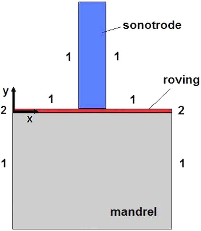
Figure 3. Geometry adopted for FE modeling and boundary conditions of the FE model: (1) convective heat flux; (2) thermal insulation; (3) constant temperature.
Governing Equations
The governing equations used to model the non-isothermal problem are the conservation equation for energy coupled with the equations accounting for the heat generated by ultrasonic waves and the heat absorbed by the melting of the matrix:
where ρ is the density, Cp the specific heat capacity, and k the thermal conductivity. Q represents the heat generation produced by ultrasonic heating and the melting heat of the PP matrix of the commingled thermoplastic roving.
The heat generation term Q in Eq. 2 is obtained when a viscoelastic material undergoing a sinusoidal deformation at high frequency dissipates a fraction of energy as a heat due to intermolecular friction. Q depends on the applied frequency, the square of strain amplitude (ε0) of the ultrasonic vibration, and the loss modulus E″ of the material (Benatar and Cheng, 1989; Benatar and Gutowski, 1989; Suresh et al., 2007; Roopa Rani and Rudramoorthy, 2013), according to the following equation:
where ω = 2πf, with f the ultrasonic frequency (20 kHz). The strain amplitude ε0 is obtained as the ratio between the maximum displacement amplitude of the ultrasonic sonotrode and the thickness of the commingled roving under consolidation. The loss modulus E″ for a viscoelastic material is the out of phase modulus and it is a measure of the energy dissipated through intermolecular friction (Ferry, 1980). The values of E″ at 20 kHz for PP is 0.32 GPa, as experimentally found by Benatar et al. (1989) at room temperature. This constant value is assumed in the model.
The term in Eq 2, representing the heat necessary to promote the polymer melting, is a function of the degree of melting Xm:
where HT is a reference value, which is assumed to be the total heat absorbed in the melting process, and the degree of melting Xm is defined as:
where H(T) is the enthalpy absorbed at the temperature T. With this assumptions, Xm ranges in the interval (0, 1). The degree of melting Xm can be expressed by the statistical approach of Greco and Maffezzoli (2003), based on the assumption that the melting peak, obtained in a dynamic DSC experiment, can be regarded as a statistical distribution of melting temperatures resulting from a distribution of lamellar thicknesses:
where TC is the temperature corresponding to the peak of the DSC signal, which is regarded as the melting temperature of the larger population of lamellar crystals; kmb is an intensity factor related to the sharpness of the distribution, and d is the shape factor.
Determination of the Input Parameters for the Model
In order to obtain the parameters TC, kmb, and d of Eq. 6, the melting behavior of the PP matrix of the commingled roving has been analyzed by dynamic DSC scans at 10°C/min. As reported in Figure 4A, a broad endothermic peak with a maximum at 438 K is observed when PP melts. As observed for many semicrystalline polymers, the melting process of PP occurs over a broad temperature interval as a consequence of the presence in the crystalline regions of lamellae of different thickness.
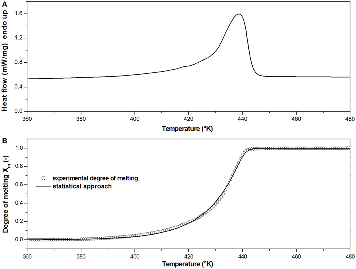
Figure 4. (A) Calorimetric thermogram at 10°C/min of the PP matrix of commingled roving; (B) Model prediction of melting integral curves according to the statistical approach of Greco and Maffezzoli (2003).
The degree of melting can be determined by the non-linear regression of DSC dynamic experiments, assuming that the heat evolved during melting is proportional to the extent of melting. The melting enthalpy absorbed at the temperature T can be obtained as a function of the temperature:
where T0 is the starting temperature. The degree of melting (Xm) of the PP matrix, defined as the integral curve of the DSC melting peak, is reported in Figure 4B. The non-linear regression of this curve according to Eq. 5 has enabled to obtain the parameters for melting modeling, reported in Table 1, which have been given as an input to the simulation.

Table 1. Parameters for melting model obtained from the non-linear regression of the experimental data with the statistical approach.
The thermal conductivity k and heat capacity Cp of the unidirectional composite are anisotropic properties with different values in the longitudinal direction and transversal direction. Moreover, k and Cp significantly vary with temperature. At room temperature, i.e., in the dry state, the composite is formed of three phases (polymer, glass, and air), while, during melting and consolidation, i.e., in the wet state, only two phases (polymer and glass) are present. In order to account for this, the values in the dry state, kdry and Cpdry have been introduced as follows:
where ΦPP, Φglass, and Φair represents the volume fraction of PP, glass fiber, and air, respectively. In order to calculate kdry and Cpdry along the x and y direction, the volume fraction of air Φair has been experimentally determined. Its value is 0.33 for the dry roving under a pressure value of 17 bar, which is the pressure applied by the sonotrode.
In a similar way, the values in the wet state, kwet and Cpwet have been determined as follows:
Moreover, in order to account for the variation of k and Cp with the temperature, the following relationships have been implemented in the model:
where Xm is the degree of melting expressed by Eq. 6.
The values of thermal conductivity and heat capacity along the longitudinal axis, kx-wet and Cpx-wet, have been determined by the rule of mixtures, while those along the transversal axis, ky-wet and Cpy-wet, have been determined by the inverse rule of mixtures commonly used also for the determination of mechanical properties of composite materials (Lionetto et al., 2014). The material properties used in the FE model are reported in Table 2.
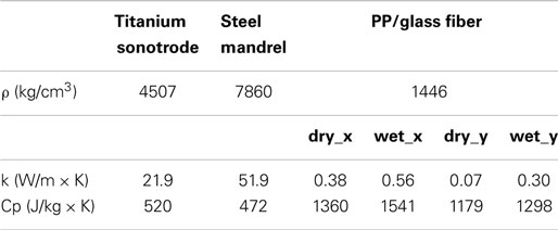
Table 2. Material properties for the FE model.
Boundary Conditions
The model defined by Eqs 2, 3, and 6 has been solved with the FE method using the commercial software Comsol Multiphysics 4.4. As boundary conditions, convective heat exchange has been adopted at the lateral walls of sonotrode and mandrel and on the upper and lower surfaces of the consolidated roving undergoing cooling, as schematically shown in Figure 3. The convective heat transfer coefficient of 5 W/m2 × K, typical of a natural convection, is used. A condition of constant temperature (298 K) has been kept on the external part of mandrel and sonotrode, far from the welding interface. Adiabatic conditions are assumed at the other boundaries.
A mesh with triangular elements with the maximum dimensions smaller than one tenth of the smallest thickness has been used.
A time dependent study has been used with the Heat Transfer module in Comsol Multiphysics 4.4 (Comsol Inc.). The time interval chosen for the simulation is between 0 and 3 s with time steps of 0.001 s.
The movement of the roving due to the mandrel rotation has been accounted in the model by setting the time range in which the sonotrode is active equal to the contact time of the roving and the sonotrode during a dynamic consolidation test. If ω and R are the rotating speed and the radius of the mandrel, respectively, then the velocity of the roving is:
If L is the length of the sonotrode in contact with the roving, then the contact time tc of the roving under the sonotrode is:
In the studied case, considering four different values of rotating speed of the mandrel (0.2, 0.3, 0.7 and 1.3 rad/s), a mandrel radius of 0.075 m and a contact length of 5 mm, a point of the commingled roving is in contact with the sonotrode for a time tc of about 0.3, 0.2, 0.1, and 0.05 s, respectively. For this reason, in order to simulate the movement of the roving, the sonotrode has been considered active only in the first 0.05, 0.1, 0.2, and 0.3 s of the simulation time interval.
Results and Discussion
Model Results
The FE analysis provides the temperature distribution in the composite during the ultrasonic impregnation and consolidation. The prediction of the temperature distribution in the composite during processing is very important since it strongly affects the quality of the thermoplastic composites. The temperature map after 0.1 s in the modeled geometry interested by the thermal gradient for a contact time tc = 0.1 s is reported in Figure 5. Only the roving in contact with the sonotrode is significantly heated reaching a temperature of about 212°C, which is well above the melting temperature of PP (about 165°C).
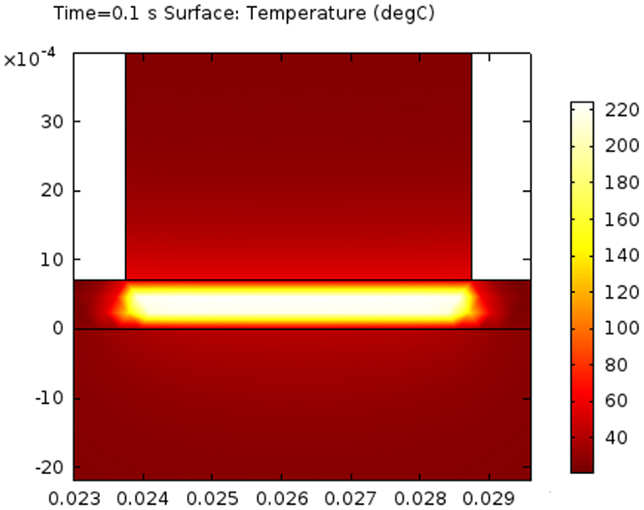
Figure 5. Temperature map at 0.1 s of the modeled geometry interested by the thermal gradient for a contact timetc = 0.1 s.
The temperature distribution at different points of the commingled roving in contact with the sonotrode is shown in Figure 6 for a contact time tc = 0.1 s. After 0.1 s, a temperature of 212°C, much higher than the melting temperature of the PP matrix, is reached in the central area below the sonotrode and in the midplane of the roving. Then, when the sonotrode is switched off, the composite is cooled until the end of simulation (3 s).
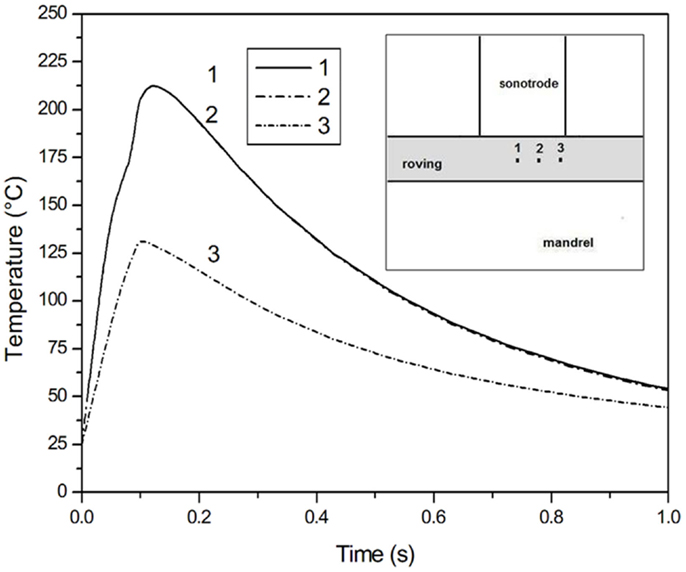
Figure 6. Temperature distribution in different points of the commingled roving in contact with the sonotrode for a contact timetc = 0.1 s.
The FE results are validated by the experimental measurement of the temperature obtained exposing the composite to ultrasonic waves for 0.2 s, as reported in Figure 7. A K-type thermocouple has been inserted between two roving plies. When the ultrasonic device is turned on, a very rapid heating is observed with the temperature reaching a value over the melting temperature of the thermoplastic matrix. A peak value of 339°C has been measured, which is in good agreement with the simulation, where the peak is reached at 343°C.
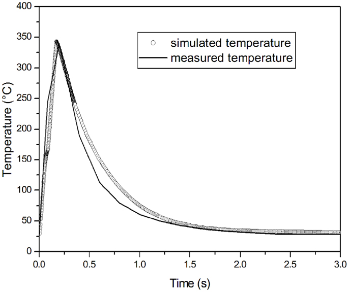
Figure 7. Comparison of numerical modeling with the experimental measurement of temperature with a sonotrode active for 0.2 s.
Figure 8 shows the temperature distribution in the midplane of the commingled roving in contact with the sonotrode for different exposure times. It is clearly observable how the exposure time affects the maximum temperature reached in the roving. Long exposure times, corresponding in a dynamic consolidation experiment to a slower mandrel rotation speed, can cause the degradation of the polymer matrix, while with a very short exposure time, e.g., 0.05 s in Figure 8, the PP matrix does not melt. The optimum value of contact time between the sonotrode and the roving, determined using the static FE model, is 0.1 s.
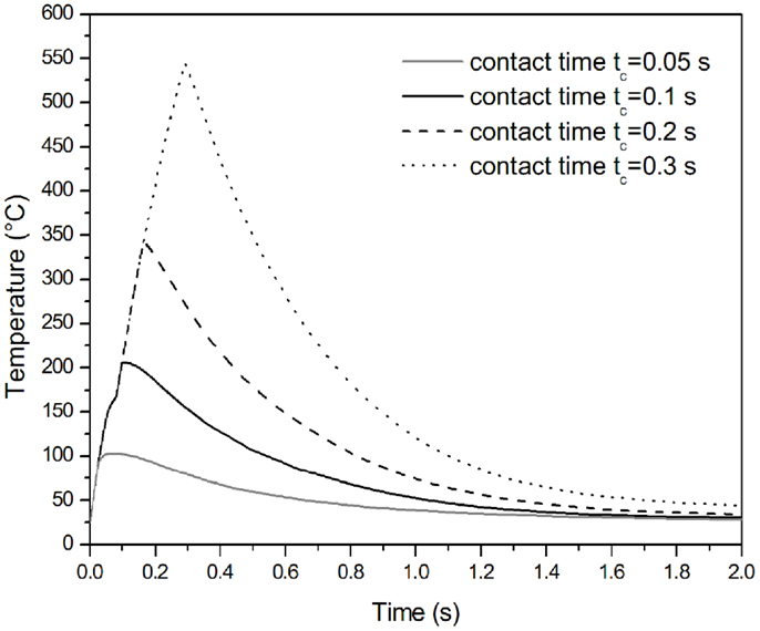
Figure 8. Temperature distribution in the midplane of the commingled roving during sonication for different times.
Figure 9A shows the calculated temperature evolution along the y axis in correspondence of the midplane of sonotrode for a process time of 0.1 s. The mandrel and the sonotrode act as heat sinks reaching 35 and 44°C, respectively, at the interface with the roving midplane between the mandrel and the sonotrode.
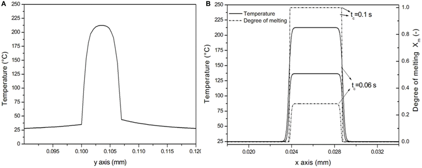
Figure 9. (A) Simulated temperature distribution along y direction after 0.1 s; (B) simulated temperature distribution and degree of melting along x direction after 0.1 s.
Figure 9B shows the calculated temperature evolution along the x axis, the direction along which the roving moves under the sonotrode during dynamic consolidation experiments. The temperature of the commingled roving is high where it is in contact with the sonotrode, sharply increasing up to 212°C. Then, it decreases reaching the room temperature value in the area not in contact with the sonotrode.
The degree of melting as a function of the space coordinates as shown in Figure 9B is also calculated, confirming the full melting of the PP matrix.
It should be noted that the temperature distribution along y direction is different from that along x direction, without a zone at constant temperature. This behavior depends on the simulation of a static process with mandrel and sonotrode acting as heat sinks. It is expected that, when simulating a dynamic process with a mandrel and a sonotrode which can heat up, the heat removed by roving at these boundaries is lower, enabling thus the roving to reach a constant temperature across the y-axis.
Sample Manufacturing and Characterization
A two stage approach has been adopted:
1. dry hoop winding of two layers of the commingled roving has been performed on a mandrel with a diameter equal to 150 mm;
2. the sonotrode is moved along the mandrel axis with a contact pressure of 17 bar while the mandrel is kept under rotation at 0.7 rad/s in order to perform matrix melting, fiber impregnation, and ply consolidation. The mandrel speed has been set in order to keep the contact time between the sonotrode and the roving at 0.1 s, the optimum value determined using the static FE model.
The pressure applied by the sonotrode, when it is contact with the roving, has been estimated by dividing the force of the sonotrode (85 N) by the contact area. Since the contact area is not perfectly parallel to the sonotrode, the obtained value of 17 bar is the minimum value. This value is however in the range of molding pressures used for thermoplastic matrix composites, which is between 10 and 60 bars (Wakeman et al., 1998; Santulli et al., 2002a,b).
The density, void content, and storage shear modulus, G12’, of samples taken from the consolidated cylinders have been measured. DMA tests in torsion on specimens cut parallel to prototype axis (90° to fiber direction) have been carried out, being the shear modulus G12’ a property dominated by the matrix and by fiber impregnation. For comparison purposes, samples with the same number of layers have been consolidated by compression molding at 200°C and 10 bar for 30 s. In Table 3 the physical and mechanical properties of the composite cylinders (two layers), obtained by filament winding and consolidated by ultrasound or by compression molding, are reported. The void content of ultrasonically consolidated samples is within the typical range found in literature for composites processed by filament winding (Henninger et al., 2002; Gennaro et al., 2011; Stefanovska et al., 2014) and compression molding (Long et al., 2001; Santulli et al., 2002a,b; Greco et al., 2007), even if with this technology the consolidation times and the compaction rates are quite different from those characteristics of the ultrasonic assisted filament winding.
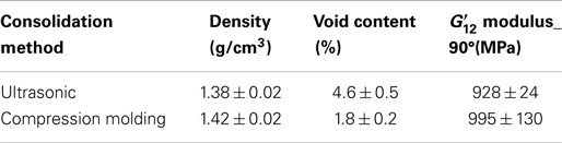
Table 3. Physical and mechanical properties of the prototype cylinders (two layers) obtained by filament winding and consolidated by ultrasound or by compression molding.
As shown in Table 3, the consolidation obtained by ultrasonic exposure is satisfactory. During processing, the ultrasonic irradiation is able to melt the thermoplastic matrix and the contact time and pressure are able to impregnate the fiber and consolidate the composite. These results suggest that the sonotrode is able to act at the same time as a heater and as a consolidating device.
The experimental values of are close to the theoretical one, 1010 MPa, which has been obtained using the Halpin–Tsai equations (Nielsen and Landel, 1994):
where
ξ is a measurement of the shape ratio of the reinforcement and depends on the fiber geometry, packing, and load conditions. For the calculation of G12’ according to Eqs 15 and 16, ξ = 1 (Nielsen and Landel, 1994), a fiber volume fraction Vf = 0.34, and a shear modulus of glass fibers and PP equal to 30 and 0.51 GPa, respectively, have been adopted (Mark, 1999).
The morphology of the consolidated composite samples analyzed by scanning electron microscopy (SEM) is reported in Figure 10. As can be seen, fibers are well impregnated but are distributed non-uniformly. Most fibers are very well impregnated while the porosity is mainly in the form of macro voids located in polymer rich regions.
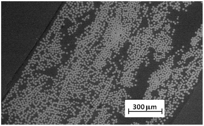
Figure 10. SEM micrographs of a polished cross-section of a consolidated composite.
Conclusion
In this work, high power ultrasound has been applied for the simultaneous deposition, impregnation and, consolidation of commingled thermoplastic rovings, made of thermoplastic filaments and glass fibers. An experimental set-up, integrating a laboratory filament winding machine with the sonotrode of an ultrasonic welding head, has been developed. During winding, the commingled roving is at the same time in contact with the mandrel and the sonotrode. The sonotrode is able to melt the matrix and to apply a pressure on the consolidating material.
With the developed experimental set-up, several two-plies prototypes of composite cylinders have been produced starting from commingled rovings made of E-glass fibers and PP filaments. The values of shear modulus obtained by mechanical characterization are very close to those predicted by the micromechanical theory of unidirectional continuous fiber composites. The void content is comparable with the values reported in literature.
The obtained physical, mechanical, and microstructural results confirm the reliability of the proposed technology for the in situ consolidation of commingled thermoplastic rovings during filament winding. Further research is in progress, focused on the optimization of the winding parameters and the implementation of a compaction roller able to increase the compaction time. In our opinion, the optimization of the proposed technique will further reduce the void content and increase the mechanical properties, thus increasing the competitive advantage of the ultrasonic assisted filament winding.
Finally, a FE model has been proposed in order to compute the temperature distribution in the composite during exposure to ultrasound in static experiments, using an energy balance accounting for the heat generated by ultrasound and for polymer melting. The simulation results have been validated by the measurement of the temperature evolution during static ultrasonic consolidation.
Conflict of Interest Statement
The authors declare that the research was conducted in the absence of any commercial or financial relationships that could be construed as a potential conflict of interest.
References
Ageorges, C., and Ye, L. (2001). Resistance welding of thermosetting composite/thermoplastic composite joints. Compos. Part A Appl. Sci. Manuf. 32, 1603–1612. doi: 10.1016/S1359-835X(00)00183-4
Ageorges, C., Ye, L., and Hou, M. (2001). Advances in fusion bonding techniques for joining thermoplastic matrix composites: a review. Compos. Part A Appl. Sci. Manuf. 32, 839–857. doi:10.1016/S1359-835X(00)00166-4
Ahmed, T. J., Stavrov, D., Bersee, H. E. N., and Beukers, A. (2006). Induction welding of thermoplastic composites-an overview. Compos. Part A Appl. Sci. Manuf. 37, 1638–1651. doi:10.1016/j.compositesa.2005.10.009
Amancio-Filho, S. T., and dos Santos, J. F. (2009). Joining of polymers and polymer–metal hybrid structures: recent developments and trends. Polym. Eng. Sci. 49, 1461–1476. doi:10.1002/pen.21424
ASTM D 792. (2008). Standard Test Method for Density and Specific Gravity (Relative Density) of Plastics by Displacement. West Conshohocken, PA: ASTM International.
Ávila-Orta, C., Espinoza-González, C., Martínez-Colunga, G., Bueno-Baqués, D., Maffezzoli, A., and Lionetto, F. (2013). An overview of progress and current challenges in ultrasonic treatment of polymer melts. Adv. Polym. Technol. 32, E582–E602. doi:10.1002/adv.21303
Benatar, A., and Cheng, Z. (1989). Ultrasonic welding of thermoplastics in the far field. Polym. Eng. Sci. 29, 1699–1704. doi:10.1002/pen.760292312
Benatar, A., Eswaran, R. M., and Nayar, S. K. (1989). Ultrasonic welding of thermoplastics in the near-field. Polym. Eng. Sci. 29, 1689–1698. doi:10.1002/pen.760292311
Benatar, A., and Gutowski, T. G. (1989). Ultrasonic welding of PEEK graphite APC-2 composites. Polym. Eng. Sci. 29, 1705–1721. doi:10.1002/pen.760292313
Dobrzanski, L. A., Domagala, J., and Silva, J. F. (2007). Application of Taguchi method in the optimisation of filament winding of thermoplastic composites. Archives Mater. Sci. Eng. 28, 133–140.
Fernandez Villegas, I., and Bersee, H. E. N. (2010). Ultrasonic welding of advanced thermoplastic composites: an investigation on energy-directing surfaces. Adv. Polym. Technol. 29, 112–121. doi:10.1002/adv.20178
Fernandez Villegas, I., Moser, L., Yousefpour, A., Mitschang, P., and Bersee, H. E. N. (2013). Process and performance evaluation of ultrasonic, induction and resistance welding of advanced thermoplastic composites. J. Thermoplast. Compos. Mater. 26, 1007–1024. doi:10.1177/0892705712456031
Gennaro, R., Montagna, F., Maffezzoli, A., Fracasso, F., and Fracasso, S. (2011). On-line consolidation of commingled polypropylene/glass roving during filament winding. J. Thermoplast. Compos. Mater. 24, 789–804. doi:10.1177/0892705711401849
Greco, A., and Maffezzoli, A. (2003). Statistical and kinetic approaches for linear low-density polyethylene melting modeling. J. Appl. Polym. Sci. 89, 289–295. doi:10.1002/app.12079
Greco, A., Musardo, C., and Maffezzoli, A. (2007). Flexural creep behaviour of PP matrix woven composite. Compos. Sci. Technol. 67, 1148–1158. doi:10.1016/j.compscitech.2006.05.015
Henninger, F., and Friedrich, K. (2002). Thermoplastic filament winding with online-impregnation. Part A: process technology and operating efficiency. Compos. Part A Appl. Sci. Manuf. 33, 1479–1486. doi:10.1016/S1359-835X(02)00135-5
Henninger, F., Hoffmann, J., and Friedrich, K. (2002). Thermoplastic filament winding with online-impregnation. Part B. Experimental study of processing parameters. Compos. Part A Appl. Sci. Manuf. 33, 1677–1688. doi:10.1016/S1359-835X(02)00135-5
Lionetto, F., Calò, E., Di Benedetto, F., Pisignano, D., and Maffezzoli, A. (2014). A methodology to orient carbon nanotubes in a thermosetting matrix. Compos. Sci. Technol. 96, 47–55. doi:10.1016/j.compscitech.2014.02.016
Liu, S. J., Chang, T., and Hung, S. W. (2001). Factors affecting the joint strenght of ultrasonically welded polypropylene composite. Polym. Compos. 22, 132–141. doi:10.1002/pc.10525
Long, A. C., Wilks, C. E., and Rudd, C. D. (2001). Experimental characterisation of the consolidation of a commingled glass/polypropylene composite. Compos. Sci. Technol. 61, 1591–1603. doi:10.1016/S0266-3538(01)00059-8
Mondo, J., Wijskamp, S., and Lenferink, R. (2012). “Overview of thermoplastic composite ATL and AFP technologies,” in 2nd Internat. Confer. Exhibit. Thermoplastic Composites ITHEC 2012, (Bremen: WFB Wirtschaftsforderung Bremen GmbH), 74–78.
Nielsen, L. E., and Landel, R. F. (1994). Mechanical Properties of Polymers and Composites. New York, NY: Marcel Dekker.
Ning, H., Vaidya, U., Janowski, G. M., and Husman, G. (2007). Design, manufacture and analysis of a thermoplastic composite frame structure for mass transit. Compos. Struct. 80, 105–116. doi:10.1016/j.compstruct.2006.04.090
Roopa Rani, M., and Rudramoorthy, R. (2013). Computational modeling and experimental studies of the dynamic performance of ultrasonic horn profiles used in plastic welding. Ultrasonics 53, 763–772. doi:10.1016/j.ultras.2012.11.003
Pubmed Abstract | Pubmed Full Text | CrossRef Full Text | Google Scholar
Santulli, C., Gil, R. G., Long, A. C., and Clifford, M. J. (2002a). Void content measurements in commingled E-glass/polypropylene composites using image analysis from optical micrographs. Sci. Eng. Compos. Mater. 10, 77–90. doi:10.1515/SECM.2002.10.2.77
Santulli, C., Brooks, R., Rudd, C. D., and Long, A. C. (2002b). Influence of microstructural voids on the mechanical and impact properties in commingled E-glass/polypropylene thermoplastic composites. Proc. IME J. Mater. Des. Appl. 216, 85–100.
Sinmazcelik, T. (2006). Natural weathering effects on the mechanical and surface properties of polyphenylene sulphide (PPS) composites. Mater. Des. 27, 270–277. doi:10.1016/j.matdes.2004.10.022
Stefanovska, M., Samakoski, B., Risteska, S., and Maneski, G. (2014). Influence of some technological parameters on the content of voids in composite during on-line consolidation with filament winding technology. Int. J. Chem. Nucl. Mater. Metall. Eng. 8, 398–402.
Suresh, K. S., Roopa Rani, M., Prakasan, K., and Rudramoorthy, R. (2007). Modeling of temperature distribution in ultrasonic welding of thermoplastics for various joint designs. J. Mater. Process. Technol. 186, 138–146. doi:10.1016/j.jmatprotec.2006.12.028
Tierney, J., and Gillespie, J. W. (2006). Modeling of in-situ strength development for the thermoplastic composite tow placement process. J. Compos. Mater. 40, 1487–1506. doi:10.1177/0021998306060162
Tolunay, M. N., Dawson, P. R., and Wang, K. K. (1983). Heating and bonding mechanisms in ultrasonic welding of thermoplastics. Polym. Eng. Sci. 23, 726–733. doi:10.1002/pen.760231307
Wakeman, M. D., Cain, T. A., Rudd, C. D., Brooks, R., and Long, A. C. (1998). Compression moulding of glass and polypropylene composites for optimized macro- and micro-mechanical properties. Part I: commingled glass and polypropylene. Compos. Sci. Technol. 58, 1879–1898. doi:10.1016/S0266-3538(98)00011-6
Ye, L., Friedrich, K., Kastel, J., and May, Y. W. (1995). Consolidation of unidirectional CF/PEEK composites from commingled yarn prepreg. Compos. Sci. Technol. 54, 349–358. doi:10.1016/0266-3538(95)00061-5
Keywords: thermoplastic composites, ultrasonic, consolidation, viscoelastic heating, filament winding, finite element method, process modeling, polypropylene
Citation: Lionetto F, Dell’Anna R, Montagna F and Maffezzoli A (2015) Ultrasonic assisted consolidation of commingled thermoplastic/glass fiber rovings. Front. Mater. 2:32. doi: 10.3389/fmats.2015.00032
Received: 28 January 2015; Accepted: 27 March 2015;
Published online: 21 April 2015.
Edited by:
Patricia Krawczak, École Nationale Supérieure des Mines de Douai, FranceReviewed by:
Chung Hae Park, École Nationale Supérieure des Mines de Douai, FranceVéronique Michaud, École Polytechnique Fédérale de Lausanne, Switzerland
Ralf Schledjewski, Montanuniversität Leoben, Austria
Copyright: © 2015 Lionetto, Dell’Anna, Montagna and Maffezzoli. This is an open-access article distributed under the terms of the Creative Commons Attribution License (CC BY). The use, distribution or reproduction in other forums is permitted, provided the original author(s) or licensor are credited and that the original publication in this journal is cited, in accordance with accepted academic practice. No use, distribution or reproduction is permitted which does not comply with these terms.
*Correspondence: Alfonso Maffezzoli, Materials Science and Technology Group, Department of Engineering for Innovation, University of Salento, via per Monteroni, Lecce 73100, Italy e-mail: alfonso.maffezzoli@unisalento.it