Structure and Corrosion Resistance of Cerium-Oxide Films on AZ31 as Deposited by High-Power Ultrasound Supported Conversion Chemistry
 Chen-Ni Liu
 Markus Wiesener
 Ignacio Giner
 Guido Grundmeier*
- Department of Chemistry, Technical and Macromolecular Chemistry, University of Paderborn, Paderborn, Germany
In the present study, a conversion layer mainly composed by cerium oxide was prepared by means of a novel ultrasound-assisted coating process. The formation of a conversion layer on top of the Mg alloy provides physical barrier properties improving the corrosion protection. In addition, the incorporation of cerium oxide within the coating enables the formation of a protective layer on the pores and defects, inhibiting localized corrosion. The chemical composition of the conversion layer was evaluated by means of Raman spectroscopy, FT-IR spectroscopy, and XPS. The prepared porous films were rich in Ce4+ and featured a very low content of oxygen-deficient cerium oxide. FE-SEM measurements were performed in order to assess the morphology of the prepared coating revealing homogeneous and uniform surfaces. Self-repair ability was verified by monitoring capacitance of the system after polarization by means of electrochemical impedance spectroscopy. Additionally, Raman spectroscopic measurements showed presence of cerium ions in defect sites, which may suggest self-repair mechanism.
Introduction
Magnesium alloys are widely used in the realm of engineering as light material due to their excellent mechanical and physical properties. Their low density and high specific strength make them suitable for lightweight applications (Kainer, 2003).
However, the most important disadvantage of magnesium is its poor corrosion resistance in aqueous environments. Since the standard potential of Mg is extremely negative [−2.37 V (NHE)], when combined with other alloying metals with higher standard potential, Mg is prone to bimetallic corrosion (Friedrich and Mordike, 2006). Therefore, an effective corrosion protection is crucial. Galvanic corrosion might be minimized by using ultrapure magnesium alloys avoiding corrosion catalysts like iron, nickel, and copper. In order to improve the mechanical properties of the ultrapure Mg alloys, alloying with aluminum or zirconium are essential (Song, 2005).
Another well-established approach to inhibit the corrosion of the Mg alloys is the application of inorganic and organic coatings onto the metal substrates. Organic coatings are economically the most efficient approach for corrosion and wear protection, providing additional physical properties to the alloy, such as optical appearance, conductivity, self-cleaning effect, etc. (Grundmeier et al., 2000; Hu et al., 2012). In addition, corrosion inhibitors can be incorporated within the organic coating leading to an enhancement of the corrosion resistance. Galio et al. (2010) presented new anticorrosive coatings for the AZ31 Mg alloy based on hybrid sol–gel films doped with 8-Hydroxyquinoline (8-HQ) as corrosion inhibitor. Their results indicated an enhancement of the corrosion protection due to the formation of stable complexes Mg(8-HQ) that retards the propagation of corrosion products blocking the microporous and microdefects within the sol–gel film. Lamaka et al. developed a complex anticorrosion protection coating for ZK30 Mg alloy consisting of a porous oxide layer produced by spark anodizing loaded with Ce3+. It was found that the presence of Ce ions blocked the pores and prevented penetration of corrosive medium through the thin barrier due to the formation of stable and insoluble Cerium hydroxides (Lamaka et al., 2009). A major challenge in the preparation of organic coatings is their insufficient hydrolytic stability against the alkaline environments related with the corrosion of magnesium (Hu et al., 2012).
The formation of inorganic conversion and passivation layers is a common approach to protect Mg-alloys. Typically, the thickness of the conversion layer is about 1–5 μm and mainly consists of a mixture of both oxides and hydroxides (Friedrich and Mordike, 2006). Lostak et al. developed Zr-based conversion layers on Zn–Al–Mg alloy-coated steels. They reported that the deposited thin film provide an effective corrosion protection based on the excellent electronic barrier properties (Lostak et al., 2014). Li et al. recently proposed a green and efficient alternative by forming a conversion layer which comprised a Mg2+ decanoate complex and Mg(OH)2. The corrosion protection was comparable to that of a chromate conversion layer (Li et al., 2013). However, conversion layers usually lack homogeneity leading to the apparition of cracks and defects within the film, which may lead to malfunction of the conversion layer (Wang et al., 2009; Lei et al., 2014). In order to avoid this, the cracks and defects have to be sealed subsequently (Friedrich and Mordike, 2006). Ce-based conversion layers have been identified as potential self-healing inhibitors for the corrosion resistance of different alloys. Lin et al. introduced cerium conversion coatings (CeCCs) on AZ31 by immersion of the substrate into a cerium nitrate solution (Lin and Fang, 2005). Unfortunately, the produced CeCCs were inhomogeneous and showed cracks on the surface which might decrease corrosion resistance (Lin and Fang, 2005). The cracks are the result of stress induced during the drying procedure at room temperature, which may even result in the partial delamination of the conversion layer (Lin and Fang, 2005). The conversion process was improved by addition of H2O2, a strong oxidant, which accelerates precipitation of the conversion layer by promoting dissolution and oxidation of the substrate (Lin and Li, 2006; Lei et al., 2014). Additionally, Ce(III) can be oxidized to Ce(IV), which leads to CeCCs with mixed oxidation state.
Recently ultrasound was introduced as new method for application of cerium oxide on aluminum alloys (Skorb et al., 2010). Depending on the intensity of irradiation, the density of the cerium/aluminum oxide network can be tuned. The network exhibited good adhesion to metal surfaces and led to an enhancement of corrosion resistance (Skorb et al., 2010).
In this study, we present a new H2O2-free experimental approach for producing uniform coatings with improved corrosion properties. We could determine that the ultrasound-assisted coating process lead to the formation of crack-reduced Ce-coatings in minimized time than those achieved by previously reported methods (Lin and Fang, 2005). Additionally, we monitored the self-repair effect in the coatings by means of electrochemical impedance and Raman spectroscopy.
Materials and Methods
Materials and Chemicals
Magnesium alloy AZ31 was used as substrate (MgF Magnesium Flachprodukte GmbH, Freiberg, Germany). Ethanol (p.a.), aluminum nitrate nonahydrate (p.a.), citric acid monohydrate (≥ 99.5%), glycolic acid (70% aqueous), and sodium hydroxide (p.a.) were used as received by Merck KGaA, Darmstadt. Cerium (III) nitrate hexahydrate (99%) was purchased from Sigma-Aldrich. Ultrapure water was gained by SG Ultra Clear UV Plus (Evoqua Water Technologies, Günzburg, Germany).
Samples of 1 cm × 2 cm size were polished successively with SiC paper (grit P240, P600, P1000, P2500, and P4000) until a mirror-like finish was reached. Afterwards, samples were cleaned with cotton wool soaked with ethanol before additional cleaning in ethanol for 10 min in an ultrasonic bath (Ultrasonic Cleaner, 45 kHz, 120 W, VWR International GmbH, Darmstadt, Germany) was performed. After rinsing with ultrapure water samples were etched in stirred acidic solution at room temperature for 30 s according to Bender (glycolic acid, aluminum nitrate, and citric acid) followed by subsequent rinsing with ultrapure water (Bender et al., 2013). Finally samples were neutralized in stirred 4 M sodium hydroxide solution for 30 s, rinsed with ultrapure water, and dried in cleaned air stream.
Freshly cleaned samples were radiated in aqueous 0.05 mol/l cerium (III) nitrate hexahydrate solution for 2 min by an ultrasonic homogenizer UIP 1000 hd equipped with a booster and a Titanium-sonotrode with a diameter of 2.2 cm (Hielscher Ultrasonics, Teltow, Germany). The distance between the sonotrode and the sample was adjusted to 3 cm and the amplitude of the homogenizer was set to 50%. After ultrasonic treatment, samples were rinsed with ultrapure water and dried in a cleaned air stream.
Characterization
FE-SEM investigations were performed by means of a FE-SEM “NEON 40” equipped with EDS (Carl Zeiss SMT AG, Oberkochen, Germany).
Preparation of cross-section polish was performed by means of Ion Beam Milling System Leica EM TIC 3X.
XPS measurements were performed by means of an Omicron ESCA + system (Omicron NanoTechnology GmbH, Germany) operated at a base pressure of <5 × 10⁻¹⁰ mbar. The system is equipped with a hemispherical energy analyzer and the element spectra were recorded at a pass energy of 25 eV. For photoelectron excitation, a monochromated Al Kα (1486.7 eV) X-ray source with a spot diameter of 600 μm was used. The take-off angle of the detected photoelectrons was 60° with respect to the surface plane. The information depth obtained is estimated to be around 2 nm. The calibration of the spectra was performed using the C 1s peak (binding energy, BE = 285 eV) as an internal reference. For data evaluation, the Casa-XPS software was used (Casa Software Ltd., Japan). Quantification of the XPS data was performed by integration of the peaks taking into account the relative sensitivity factors of the elements as well as background correction.
Raman spectra were recorded using a dispersive spectrometer “In-Via” (Renishaw, Gloucestershire, UK) excited by a RL633 nm HeNe Laser with a power of 8.8 mW using a 50× objective.
For FT-IRRAS measurements, a Vertex 70 equipped with a Hyperion 1000 microscope (Bruker Corporation, Billerica, USA) was used. Using a GIR-Objective, for a typical measurement 256 individual spectra, each with a spectral resolution of 4 cm−1, have been averaged for better signal-to-noise ratio. Analysis was performed using the OPUS software package and a gold mirror as reference.
Electrochemical measurements were performed in a custom designed cell with a three electrode set-up using Ag/AgCl as reference electrode, Pt-wire as counter electrode and the coated Mg-sample as working electrode. As an electrolyte, either a solution consisted of ultrapure water (Millipore) was adjusted to a pH of 10 based on a concentration of NaOH of 10−4 mol/l with addition of NaCl of 0.05 mol/l or ultrapure water with addition of 3.5 wt.% NaCl was used. A Reference 600 Potentiostat (Gamry Instruments, Warminster, USA) was chosen for linear sweep voltammetry and Electrochemical impedance analysis (EIS).
Electrochemical impedance analysis was performed at open circuit potential with an amplitude of 10 mV in the range of 100 kHz–0.1 Hz.
In addition, self-repair studies were performed in the same setup as mentioned above. In order to accelerate the corrosion process, the cerium oxide-coated samples were polarized to +0.5 V vs. OCP for an hour. Afterwards, self-repair ability during immersion was monitored by electrical impedance spectroscopy. The samples were subsequently analyzed by microscopic Raman spectroscopy.
Results and Discussion
Film Morphology
The FE-SEM images (see Figure 1) illustrate the change in surface morphology of AZ31 before and after ultrasound treatment in cerium nitrate solution. Figure 1A shows the AZ31 surface directly after polishing and etching, revealing the grain boundaries and an average grain size of few micrometers. After the film deposition process, the surface is homogeneously covered with a rough coating.
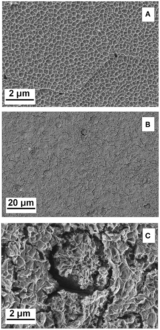
Figure 1. (A–C) SEM images of surface; (A) sample after pre-treatment; (B) sample after ultrasound-assisted surface film formation and (C) higher magnification of the surface coating.
The high resolution FE-SEM image of the deposited film revealed a porous network structure with few cracks as shown in Figures 1B,C. A close up of the coating (Figure 1C) revealed an interlaced fibers-like structure, similar to previously reported CeCCs, which were severely cracked after 20 min of immersion (Lin and Fang, 2005). This structure is in contrast to CeCCs gained by addition of H2O2 at shorter treatment times, where morphologies of round or nodulous/“honey-comb”-like nanoparticles were reported (Castano et al., 2014; Lei et al., 2014). EDS mappings of the coating, which are shown in Figure 2, reveal the elemental distribution of the metal ions. An increased concentration of cerium and oxygen was observed in the porous coating area; increased magnesium concentration was observed in the cracks.
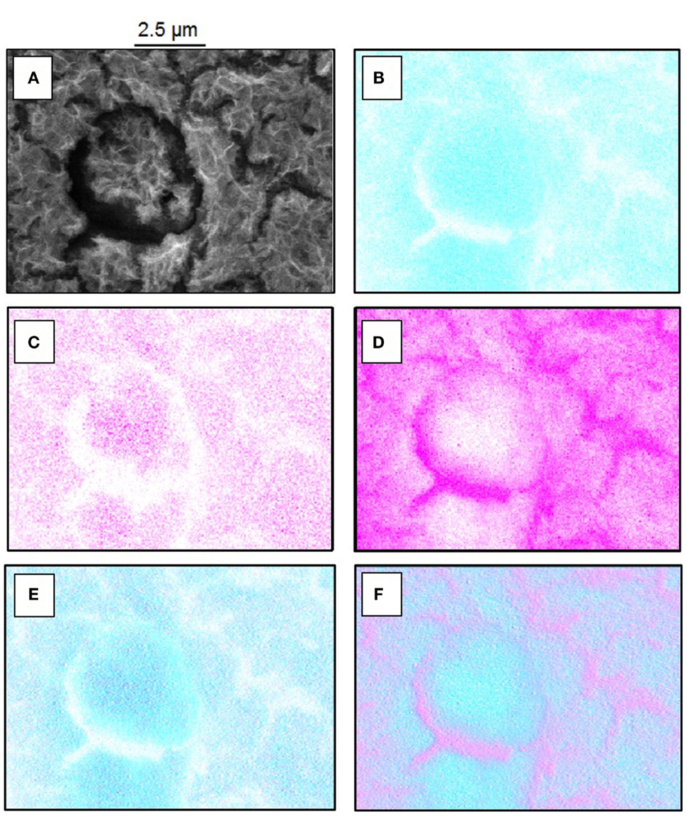
Figure 2. (A–F) FE-SEM and EDS mappings of cerium oxide-coated sample. (A) FE-SEM picture for overview, (B) EDS mapping of oxygen, (C) EDS mapping of cerium, (D) EDS mapping of magnesium, (E) overlay of cerium (magenta) and oxygen (cyan blue), and (F) overlay of magnesium (magenta) and oxygen (cyan blue).
The cross section as prepared by ion milling and analyzed by FE-SEM confirms the porous nature of the cerium oxide layer as shown in Figure 3. It seems that a compact layer with a thickness below 100 nm is formed under the porous top film.
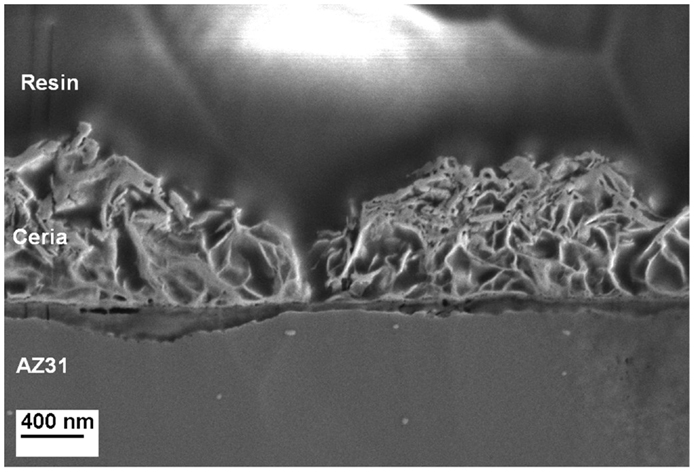
Figure 3. Cross-sectional analysis of a Ce-oxide coated sample illustrating the morphology of the coating and the size of a crack.
Based on the EDS analysis and SEM images, it can be concluded that the porous structure is composed by a mixture of Ce and Mg oxide about 1 μm thick. The cracks observed over the surface present a width of 200 nm. The compact layer between the Mg alloy and the oxide coating is rich in Mg oxide compounds.
Analysis of the Chemical Composition
In addition to the FE-SEM analysis, Ce-oxide layers were further characterized by means of FT-IRRAS. Spectra of polished and etched AZ31 and the coated sample are shown in Figure 4 and the peak assignments according to literature are listed in Table 1. It was found that the AZ31 spectrum featured peaks characteristic for carbonates. In comparison, the hydroxide and carbonate peaks are strongly increased after the US-surface treatment.
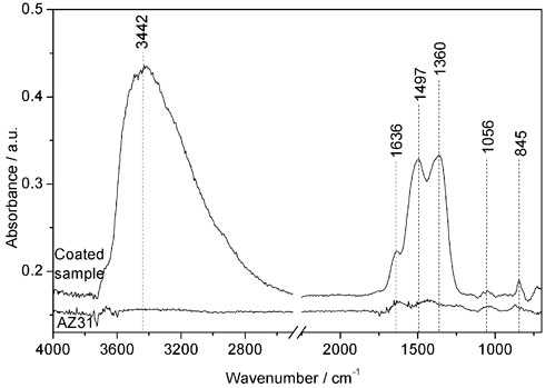
Figure 4. IRRAS data of AZ31 and the Ce oxide-coated sample.
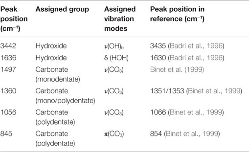
Table 1. Relevant assigning peaks of IRRAS spectra.
XPS survey spectra of AZ31 revealed the presence of carbon, oxygen, magnesium and aluminum in the surface near region as shown in Figure 5. In addition to that, cerium and nitrogen were detected for the coated substrate. Table 2 summarizes the atomic composition found for all major elements before and after ultrasonic treatment. After the ultrasound treatment, the oxygen content increased, the magnesium concentration decreased from about 14 to 3 at.%, and aluminum was not detected. This leads to the assumption that a high coverage of the alloy was achieved as supported by the FE-SEM images in Figures 1B,C. The presence of Mg hints at the incorporation of Mg-ions in the formed Ce-oxide film.
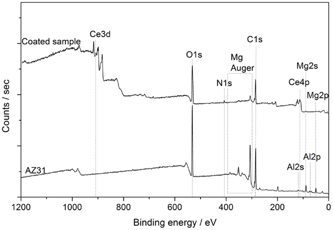
Figure 5. XPS survey spectra of AZ31 and US Ce oxide-coated AZ31.

Table 2. Elemental composition gained from XPs survey spectra.
In order to elucidate the chemical state of cerium, oxygen, and carbon, the corresponding high resolution element spectra were analyzed. The evaluation of different contributions found for those elemental spectra is summarized in Table 3. Figure 6A shows a spectrum of the Ce 3d core level for the coated sample revealing the co-existence of the oxidation states +3 and +4 of cerium (Qiu et al., 2006; Światowska et al., 2011). Both oxidation states are composed of two multiplets (ν and u), which correspond to spin-orbit coupling of electrons in the d-Orbital (3d5/2 and 3d3/2).
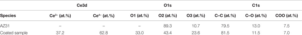
Table 3. At.% ratio of oxygen species gained from peak fitting of Ce3d, O1s, and C1s XPS spectra.
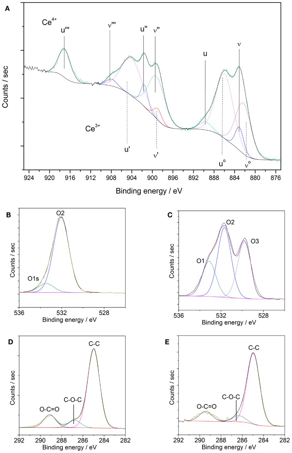
Figure 6. (A–E) XPS element spectra of AZ31 and US Ce oxide-coated AZ31. (A) Ce3d of coated sample; (B) O1s of AZ31; (C) O1s of coated AZ31; (D) C1s of AZ31 and (E) C1s of coated AZ31.
As reported previously, the Ce4+ oxidation state presents three different doublets (ν and u, ν″ and u″, ν″′ and u″′) due to the hybridization of the orbital f and d. Corresponding binding energies peaks ν, u, ν″, u″, ν″′, and u″′ are located at 882.7, 901.1, 889.1, 907.6, 898.4, and 916.0 eV, respectively. In the case of Ce3+ species only two multiplets are present (νo and uo, ν′ and u′) whose binding energy peaks are located about 880.3, 896.3, 885.2, and 902.3 eV. According to our experimental data, a mixture of both oxidation states (Ce3+ and Ce4+) is found. The satellite peak u″′ at 916.0 eV is unequivocally attributed to the Ce4+ species whereas the multiplet ν′ and u′ at about 885.2 and 902.3 eV are assigned to Ce3+ species. The at.% of Ce4+ ratio can be calculated from the individual contributions of each multiplet yielding to a value of 62.8% of Ce4+ species. Thus, the outer surface of the sonicated surfaces is dominated by the presence of Ce4+. These results are in agreement with values reported in literature about CeCCs (Li et al., 2008; Castano et al., 2014).
The high resolution elemental spectra of the O1s core level displayed in Figures 6B,C reveal a complex structure. The O1s core level was fitted with three contributions. The first component named O1 is associated to strongly adsorbed water, the presence of nitrates and carbonates (Martínez et al., 2011; Giner et al., 2013). The second component, named O2, at 531.6 eV is assigned to hydroxyl species, adsorbed oxygen species, or carbonates. The last component, named O3, appeared at lower binding energy (529.8 eV) corresponds to the oxidic species of the cerium oxide coating. In comparison, the substrate AZ31 does not feature any contributions of oxides and is dominated by hydroxides and carbonates. The binding energy of the N1s core level (not shown) corresponds to nitrate species resulting from the precursor.
The C1s spectra in Figures 6D,E were also fitted with three different contributions. The contribution at lower BE (285.0 eV) is associated to C–C species, whereas the contribution at 287.0 eV is related to C-oxidized species. The contribution with higher BE (288.5 eV) is associated to the presence of carbonates and carboxylates adsorbed species on the outer surface.
Electrochemical Analysis
Time-dependent impedance data of AZ31 and the coated substrate were measured during the immersion of the coated sample in the alkaline chloride-containing electrolyte. The data corresponding to AZ31 can be found in the Supplementary Material. The Bode plots of the coated sample show an increase in the low frequency impedance with time of immersion, reaching a constant level after 2 h (see Figures 7A,B). This indicates a decrease in pore activity of the coating.
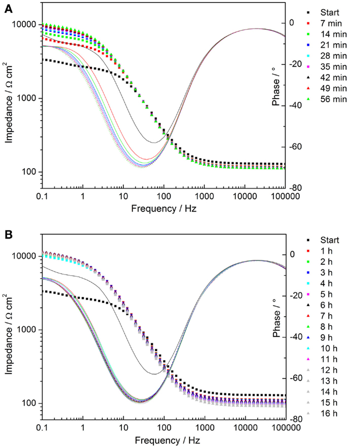
Figure 7. (A,B) Time-dependent plots of impedance measurements of cerium oxide film immersed in 1 mM NaOH with 0.05M NaCl; (A) Bode plot of evolution during first hour; (B) Bode plot of hourly development.
In order to compare the enhanced corrosion properties of obtained coatings with previously reported values, additional EIS measurements in 3.5% NaCl electrolyte on the AZ31 bare alloy and on the cerium oxide-coated one were performed. Bode plots of the results are shown in Figure 8. After 1 h of immersion, the impedance value of the bare AZ31 was around 50 Ω cm2, which is comparable to the values reported by Lei (Lei et al., 2014). The impedance value of the coated sample for the same immersion time was ~3 times higher (≈3700 Ω cm2), revealing better corrosion protection. Even after 2 h of immersion, the impedance value of the cerium oxide-coated sample was twice the reported value (≈2540 Ω cm2). Therefore, application of the cerium oxide coating on the AZ31 alloy provides improved corrosion protection.
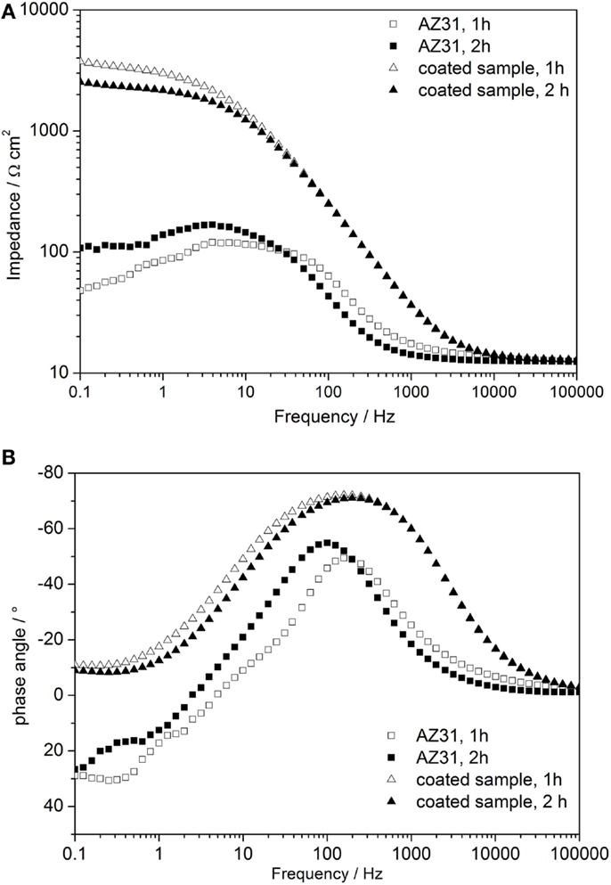
Figure 8. (A,B) Time-dependent Bode plots of impedance measurements of AZ31 and cerium oxide-coated sample immersed in 3.5 wt.% NaCl solution; (A) impedance plot and (B) phase plot.
To stimulate a corrosion process, anodic polarization of the coating was performed to damage the coating in the area of cracks or pinholes. The substrate was polarized for 1 h at + 0.5V vs. open circuit potential.
This polarization typically led to localized corrosion with spherical appearance of the corroded areas.
The time-dependent Bode plots of cerium oxide-coated samples obtained by EIS after polarization are displayed in Figures 9A,B. The corresponding evaluation of the low frequency impedance kinetics is shown in Figure 10. The evaluation of impedance for AZ31 before and after immersion is also shown for comparison. The impedance values at 0.1 Hz of the AZ31 alloy after polarization were constant over the whole immersion time studied. However, for the cerium oxide-coated samples, after polarization, the impedance at 0.1 Hz increased steeply during the first hour and finally reached a similar value as found for the non-polarized substrate. This shows that the corrosion in the formed active pits slows down over time. The inhibition of the corrosion behavior can be attributed to blocking species that originate either from the precipitation of corrosion products or from migrating cerium species from non-corroded areas.
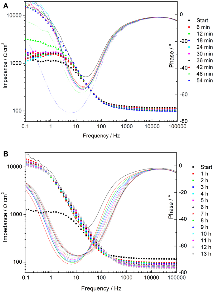
Figure 9. (A,B) Time dependent plots of impedance measurements of cerium oxide film after polarization of +0.5 V vs. Eoc, immersed in 1 mM NaOH with 0.05M NaCl; (A) Bode plot of evolution during first hour; (B) Bode plot of hourly development.
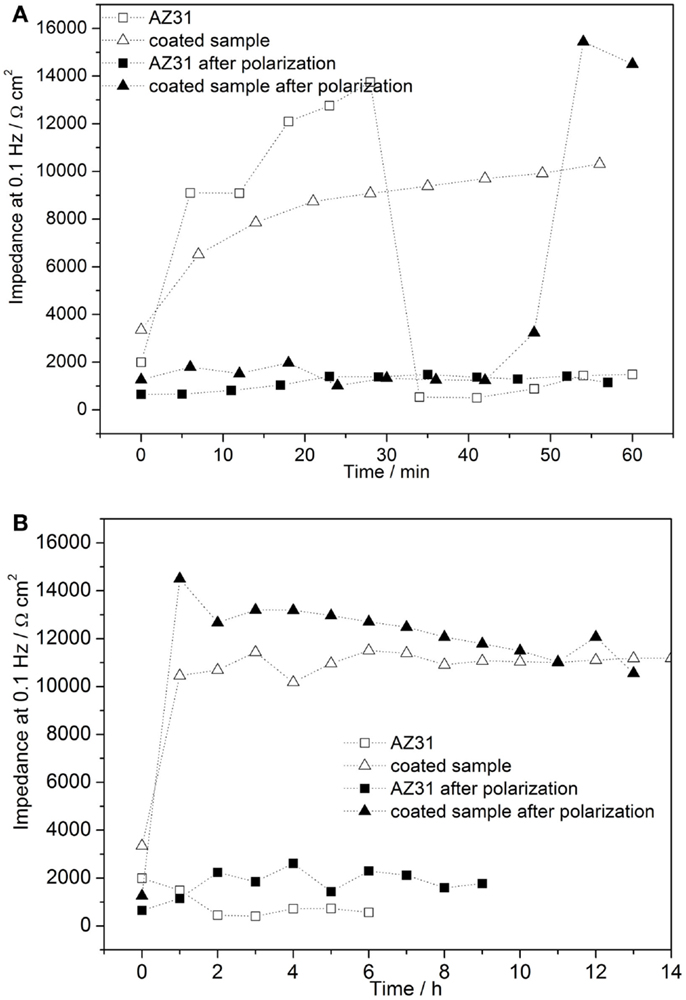
Figure 10. (A,B) Time-dependent evolution of pore resistance of coated sample after 1 h of polarization of 0.5 V vs. Eoc (A) development during first hour after and (B) hourly development.
Figure 11A shows the microscopic image of the cerium oxide coating after 1 h of anodic polarization and further immersion for 14 h. Figure 11B shows Raman spectra in the marked areas. The peak assignment of the spectra is summarized in Table 4. The spectrum of a freshly prepared coated sample features strong peaks at 454 and 1047 cm−1, which are assigned to cerium IV oxide and nitrates, respectively (Yang et al., 2014).
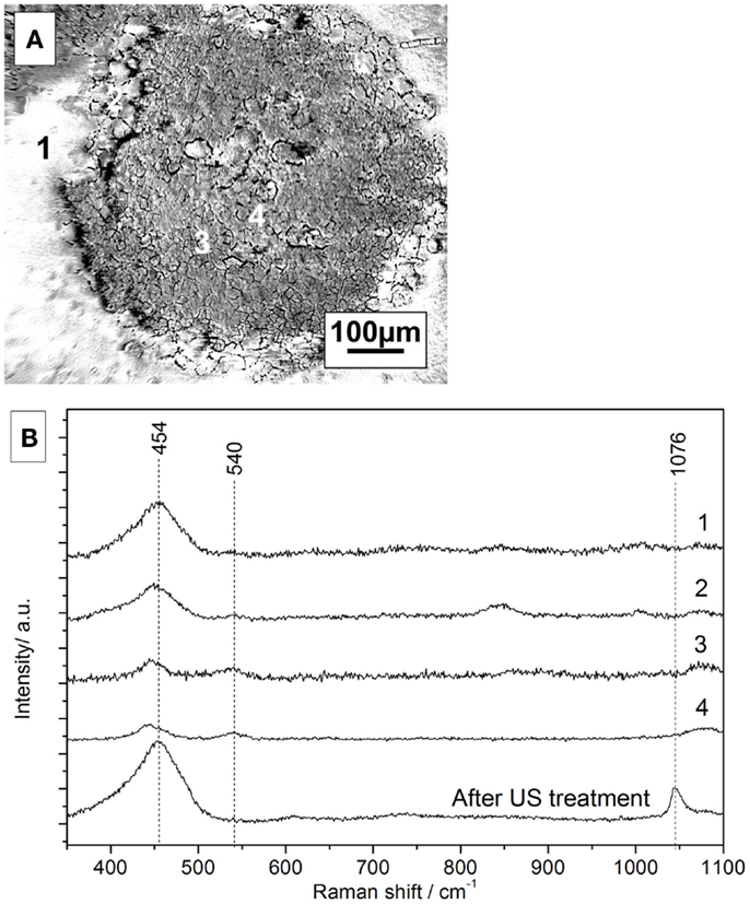
Figure 11. (A) Microscope picture of coated surface after polarization and 14 h of immersion, (B) corresponding Raman spectra of the selected areas.
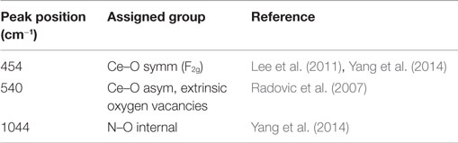
Table 4. Peak positions of relevant assigning vibration.
In the microscope image, three different areas can be distinguished. The Raman spectrum of area 1 looks similar to the spectrum of a freshly prepared sample, indicating a similar amount of cerium oxide. However, the nitrate contribution is completely diminished most probably to a slow substitution of nitrates with hydroxides in the alkaline solution.
The Raman spectrum of area 2 in the border region between the intact area and the pit shows smaller cerium oxide peaks detected in area 1. A similar trend for areas 3 and 4, which show the presence of Ce-oxide but even smaller peak intensities, is observed. However, the peak at 540 cm−1, which is assigned to re-deposited Ce(III)-oxide, is observed only in the defect areas.
This would hint at a potential self-repair ability of the conversion layer (Paussa et al., 2010).
Conclusion
Cerium oxide films with improved corrosion resistance and self-repair ability were successfully grown on AZ31 alloy by a novel ultrasound-assisted deposition technique from cerium nitrate solution. The prepared films feature a porous structure and consist mainly of cerium (IV) oxide with minor contributions of carboxylates and nitrate species as determined by SEM, XPS, Raman, and FT-IRRAS. Despite the presence of small cracks and defects over the surface, the coating provided significant corrosion protection to the AZ31 alloy. The subsequent polarization led to the formation of pinholes within the coating. The coatings revealed self-repair ability since the impedance values regained to high values after few hours of immersion. Raman spectroscopy in the defect zones revealed that Ce-oxides were redeposited in the corroded areas.
Thus, the proposed novel deposition approach opens new possibilities for the development of conversion layers of a wide variety of materials with improved features.
Conflict of Interest Statement
The authors declare that the research was conducted in the absence of any commercial or financial relationships that could be construed as a potential conflict of interest. The Guest Associate Editor Wolfram Fürbeth declares that, despite having collaborated with author Guido Grundmeier, the review process was handled objectively and no conflict of interest exists.
Acknowledgments
The authors gratefully acknowledge the financial support of the German Federation of Industrial Research Associations (AiF) within the IGF project No 18267 N “Korrosionsschutz für Magnesiumknetlegierungen durch ultraschallgeschütztes Wachstum von selbstheildenden Oxidschichten.”
Supplementary Material
The Supplementary Material for this article can be found online at https://www.frontiersin.org/article/10.3389/fmats.2015.00068
References
Badri, A., Binet, C., and Lavalley, J.-C. (1996). An FTIR study of surface ceria hydroxy groups during a redox process with H2. Faraday Trans. 92, 4669. doi: 10.1039/ft9969204669
Bender, S., Holzhausen, U., and Heyn, A. (2013). Investigations of the aqueous corrosion of pretreated magnesium alloys by means of electrochemical noise measurements. Mater. Corros. 64, 708–713. doi:10.1002/maco.201206741
Binet, C., Daturi, M., and Lavalley, J.-C. (1999). IR study of polycrystalline ceria properties in oxidised and reduced states. Catal. Today 50, 207–225. doi:10.1016/S0920-5861(98)00504-5
Castano, C. E., O’Keefe, M. J., and Fahrenholtz, W. G. (2014). Microstructural evolution of cerium-based coatings on AZ31 magnesium alloys. Surf. Coat. Technol. 246, 77–84. doi:10.1016/j.surfcoat2014.03.010
Friedrich, H. E., and Mordike, B. L. (2006). Magnesium Technology: Metallurgy, Design Data, Automotive Applications. Berlin: Springer.
Galio, A. F., Lamaka, S. V., Zheludkevich, M. L., Dick, L., Müller, I. L., and Ferreira, M. (2010). Inhibitor-doped sol–gel coatings for corrosion protection of magnesium alloy AZ31. Surf. Coat. Technol. 204, 1479–1486. doi:10.1016/j.surfcoat.2009.09.067
Giner, I., Maxisch, M., Kunze, C., and Grundmeier, G. (2013). Combined in situ PM-IRRAS/QCM studies of water adsorption on plasma modified aluminum oxide/aluminum substrates. Appl. Surf. Sci. 283, 145–153. doi:10.1016/j.apsusc.2013.06.059
Grundmeier, G., Schmidt, W., and Stratmann, M. (2000). Corrosion protection by organic coatings: electrochemical mechanism and novel methods of investigation. Electrochim. Acta 45, 2515–2533. doi:10.1016/S0013-4686(00)00348-0
Hu, R.-G., Zhang, S., Bu, J.-F., Lin, C.-J., and Song, G.-L. (2012). Recent progress in corrosion protection of magnesium alloys by organic coatings. Prog. Org. Coat. 73, 129–141. doi:10.1016/j.porgcoat.2011.10.011
Lamaka, S. V., Knörnschild, G., Snihirova, D. V., Taryba, M. G., Zheludkevich, M. L., and Ferreira, M. (2009). Complex anticorrosion coating for ZK30 magnesium alloy. Electrochim. Acta 55, 131–141. doi:10.1016/j.electacta.2009.08.018
Lee, Y., He, G., Akey, A. J., Si, R., Flytzani-Stephanopoulos, M., and Herman, I. P. (2011). Raman analysis of mode softening in nanoparticle CeO(2-δ) and Au-CeO(2-δ) during CO oxidation. J. Am. Chem. Soc. 133, 12952–12955. doi:10.1021/ja204479j
Lei, L., Wang, X., Tang, Q., Chen, S., Zhu, Z., and Xu, L. (2014). Surface characterization of growth process for cerium conversion coating on magnesium alloy and its anticorrosion mechanism. Surf. Interface Anal. 46, 556–563. doi:10.1002/sia.5570
Li, L. J., Lei, J. L., Yu, S. H., Tian, Y. J., Jiang, Q. Q., and Pan, F. S. (2008). Formation and characterization of cerium conversion coatings on magnesium alloy. J. Rare Earths 26, 383–387. doi:10.1016/s1002-0721(08)60101-5
Li, Y., Tan, C., Qi, G., Guo, J., Wang, X., and Zhang, S. (2013). Decanoate conversion layer with improved corrosion protection for magnesium alloy. Corros. Sci. 70, 229–234. doi:10.1016/j.corsci.2013.01.034
Lin, C. S., and Fang, S. K. (2005). Formation of cerium conversion coatings on AZ31 magnesium alloys. J. Electrochem. Soc. 152, B54–B59. doi:10.1149/1.1845371
Lin, C.-S., and Li, W.-J. (2006). Corrosion resistance of cerium-conversion coated AZ31 magnesium alloys in cerium nitrate solutions. Mater. Trans. 47, 1020–1025. doi:10.2320/matertrans.47.1020
Lostak, T., Maljusch, A., Klink, B., Krebs, S., Kimpel, M., Flock, J., et al. (2014). Zr-based conversion layer on Zn-Al-Mg alloy coated steel sheets: insights into the formation mechanism. Electrochim. Acta 137, 65–74. doi:10.1016/j.electacta.2014.05.163
Martínez, L., Román, E., de Segovia, J. L., Poupard, S., Creus, J., and Pedraza, F. (2011). Surface study of cerium oxide based coatings obtained by cathodic electrodeposition on zinc. Appl. Surf. Sci. 257, 6202–6207. doi:10.1016/j.apsusc.2011.02.033
Paussa, L., Rosero-Navarro, N. C., Andreatta, F., Castro, Y., Duran, A., Aparicio, M., et al. (2010). Inhibition effect of cerium in hybrid sol-gel films on aluminium alloy AA2024. Surf. Interface Anal. 42, 299–305. doi:10.1002/sia.3198
Qiu, L., Liu, F., Zhao, L., Ma, Y., and Yao, J. (2006). Comparative XPS study of surface reduction for nanocrystalline and microcrystalline ceria powder. Appl. Surf. Sci. 252, 4931–4935. doi:10.1016/j.apsusc.2005.07.024
Radovic, M., Dohcevic-Mitrovic, Z., Scepanovic, M., Grujic-Brojcin, M., Matovic, B., Boskovic, S., et al. (2007). Raman study of Ba-doped ceria nanopowders. Sci. Sintering 39, 281–286. doi:10.2298/SOS0703281R
Skorb, E., Shchukin, D., Moehwald, H., and Andreeva, D. (2010). Sonochemical design of cerium-rich anticorrosion nanonetwork on metal surface. Langmuir 26, 16973–16979. doi:10.1021/la100677d
Song, G. (2005). Recent progress in corrosion and protection of magnesium alloys. Adv. Eng. Mater. 7, 563–586. doi:10.1002/adem.200500013
Światowska, J., Lair, V., Pereira-Nabais, C., Cote, G., Marcus, P., and Chagnes, A. (2011). XPS, XRD and SEM characterization of a thin ceria layer deposited onto graphite electrode for application in lithium-ion batteries. Appl. Surf. Sci. 257, 9110–9119. doi:10.1016/j.apsusc.2011.05.108
Wang, C., Zhu, S., Jiang, F., and Wang, F. (2009). Cerium conversion coatings for AZ91D magnesium alloy in ethanol solution and its corrosion resistance. Corros. Sci. 51, 2916–2923. doi:10.1016/j.corsci.2009.08.003
Keywords: AZ31, ultrasound treatment, self-repair, cerium oxide coating, corrosion protection
Citation: Liu C-N, Wiesener M, Giner I and Grundmeier G (2015) Structure and Corrosion Resistance of Cerium-Oxide Films on AZ31 as Deposited by High-Power Ultrasound Supported Conversion Chemistry. Front. Mater. 2:68. doi: 10.3389/fmats.2015.00068
Received: 29 July 2015; Accepted: 28 October 2015;
Published: 11 November 2015
Edited by:
Wolfram Fürbeth, DECHEMA-Forschungsinstitut, GermanyReviewed by:
Sebastian Feliu, Centro Nacional de Investigaciones Metalúrgicas-CSIC, SpainFatima Montemor, Instituto Superior Técnico, Portugal
Copyright: © 2015 Liu, Wiesener, Giner and Grundmeier. This is an open-access article distributed under the terms of the Creative Commons Attribution License (CC BY). The use, distribution or reproduction in other forums is permitted, provided the original author(s) or licensor are credited and that the original publication in this journal is cited, in accordance with accepted academic practice. No use, distribution or reproduction is permitted which does not comply with these terms.
*Correspondence: Guido Grundmeier, g.grundmeier@tc.uni-paderborn.de