Dodecylamine-Loaded Halloysite Nanocontainers for Active Anticorrosion Coatings
 Jesus Marino Falcón1
 Tiago Sawczen
 Idalina Vieira Aoki
- 1Polytechnic School, University of São Paulo, São Paulo, Brazil
- 2Nanocorr – Aditivos Inteligentes e Soluções Contra Corrosão Ltd., Paraná, Brazil
Currently, the most promising approach in the corrosion protection of smart coatings is the use of nanoreservoirs loaded with corrosion inhibitors. Nanocontainers are filled with anti-corrosive agents and are embedded into a primer coating. Future prospective containers are halloysite nanotubes (HNTs) due to their low price, availability, durability, with high mechanical strength and biocompatibility. The aim of this work is to study the use of HNTs as nanocontainers for encapsulated dodecylamine for active corrosion protection of carbon steel. Halloysite clay was characterized by X-ray diffraction and TGA – thermogravimetric analysis techniques. HNTs were loaded with dodecylamine and were embedded into an alkyd primer with a weight ratio of 10 wt.%. The anti-corrosive performance of the alkyd primer doped with 10 wt.% of entrapped-dodecylamine halloysite was tested on coated carbon steel by direct exposure of the coated samples with a provoked defect into 0.01 mol/L NaCl corrosive media using electrochemical impedance spectroscopy (EIS) and scanning vibrating electrode technique (SVET). EIS and SVET measurements showed the self-healing properties of the doped alkyd coating. Coated samples were also evaluated in a salt spray chamber and the self-healing effect was unequivocally noticed.
Introduction
Corrosion of metals is one of the serious technological problems, resulting in huge economic losses, especially in the aerospace, automotive, and petroleum industries. For this reason, a variety of methods such as cathodic protection, metallic coatings, and polymeric coating systems were developed to overcome it. However, if this barrier is partially disrupted, the coating itself cannot stop the corrosion process. One of the possible solutions to achieve active corrosion protection is to introduce an ecofriendly corrosion inhibitor directly into the coating, providing release of the inhibitor, and termination of the corrosion propagation at already damaged corrosion defects (Shchukin et al., 2008). Expected undesirable reactions between inhibitor molecule and constituents of the coating polymeric matrix are the main reasons for avoiding the direct introduction of inhibitors into coatings and trying to encapsulate them (Zheludkevich et al., 2007).
Accordingly, nanocontainers are loaded with corrosion inhibitors and dispersed in organic coatings applied as primers. These nanomaterials have the ability to release encapsulated inhibitors in a controlled manner, which can be tuned to coincide with an increase of the aggressiveness in the surrounding environment or corrosion initiation on the metallic substrates (Hu et al., 2005; Zheludkevich et al., 2005, 2007; Suryanarayana et al., 2008; Wu et al., 2008; Tedim et al., 2010; Evaggelos et al., 2011; Nesterova et al., 2011). When the local environment undergoes changes or if the corrosion process is started on the metal surface, the nanocontainers release encapsulated active material (inhibitor) directly into the damaged area, thus preventing undesirable leakage of the inhibitor and reduction of the barrier properties of the whole applied film (Zheludkevich et al., 2007; Andreeva et al., 2008, 2010; Shchukin et al., 2008; Borisova et al., 2011). Recently, a review on smart coatings stresses the use of smart nanocontainers for the enhancement of active anticorrosion performance in protective coatings (Montemor, 2014). Different types of inorganic corrosion inhibitors include chromates, phosphates, molybdates, and nitrites. One of the disadvantages of inorganic inhibitors is that some of them are toxic. For example, chromates are proven to cause several diseases, including cancer and are forbidden in Europe since 2007, for common usage. Therefore, introduction of ecofriendly corrosion inhibitors for protective coatings is a very intriguing challenge (Zheludkevich et al., 2007). For instance, the large-scale implementation of the nanocontainer-based coatings is limited by the high nanocontainers price. This calls for the finding of low-cost nanocontainers, which can be employed successfully in self-healing or smart coatings. One of the prospective future nanocontainers that can be industrially mined is halloysite clay nanotubes (Yuan et al., 2015). Often, long and thin tubular systems are highly desirable, since for the same amount of cargo (compared to spherical capsules), they exhibit superior aero and hydrodynamic properties and thus better processability (Suh et al., 2011). Thus, the use of halloysite nanotubes (HNTs) has become probably one of the best proposals due to their low cost and ability to encapsulate a range of active agents within their structure followed by their retention and triggered release (Shi et al., 2011; Kamble et al., 2012; Rawtani and Agrawal, 2012; Yuan et al., 2012; Joshi et al., 2013; Lvov et al., 2014). Halloysite occurs mainly in two different six polymorphs, with a interlayer where water molecules are entrapped; the hydrated form (basal distance around 10 Å) with the minimal formula of Al2Si2O5 (OH)4⋅2H2O, and the dehydrated form (basal distance around 7 Å) with the minimal formula of Al2Si2O5(OH)4 which is identical to that of kaolinite. The hydrated form converts irreversibly into the dehydrated form when dried at temperatures below 100°C (Nicolini et al., 2009). Various inorganic and organic species can be used in the intercalation of halloysite into its interlayer spaces, such as formamide, dimethylsulfoxide, urea, potassium acetate, aniline, and hydrazine. When intercalation takes place with larger molecules, the basal distance between interlayers is higher than 10 Å (Frost et al., 2010; Wilson, 2013).
Different types of inhibitors can be loaded within halloysite lumen and used for the doping of coatings. Fix et al. (2009) investigated the corrosion protection efficiency of aluminum AA2024 alloy covered with a sol–gel matrix, which was doped with inhibitor-filled HNTs. The corrosion protection efficiency was monitored via scanning vibrating electrode technique (SVET). A self-healing effect of the sol–gel doped with inhibitor-loaded HNTs was demonstrated. Abdullayev et al. (2009) evaluated the anti-corrosive performance of the sol–gel coating and paint loaded with 2–5 wt.% of halloysite-entrapped benzotriazole applied on copper and 2024-allumium alloy by direct exposure to corrosive media. To characterize the halloysite structure scanning electron microscope and transmission electron microscope were used. The corrosion inhibition efficiency of halloysite nanocontainers for aluminum and copper samples was monitored by SVET. A good corrosion protection was observed for halloysite-loaded samples in comparison to samples coated with only sol–gel. Shchukin et al. (2008) studied the anticorrosion properties of the sol–gel films doped with HNTs loaded with corrosion inhibitor (2-mercaptobenzothiazole) and outer surfaces layer-by-layer covered with polyelectrolyte multilayers. An increase in the anticorrosion properties were reached for the samples coated with sol–gel doped with HNTs. The use of dodecylamine encapsulated in halloysite was proposed to provide corrosion protection to coatings (Joshi, 2014). Kinetics of releasing of corrosion inhibitors encapsulated within halloysite lumen was also studied. Lvov et al. (2014) studied kinetics of releasing of drugs and proteins from HNTs in water. The results showed that halloysite inner lumen can store and release molecules in a controllable manner resulting useful for applications in drug delivery, antimicrobial materials, and self-healing polymeric composites. Yuan et al. (2012) studied the loading and the release of an anionic dye compound from functionalized HNTs. The results showed that functionalization of HNTs makes pH an external trigger for controlling the loading and the subsequent release of the encapsulated species. The main objective of this article is to encapsulate dodecylamine as corrosion inhibitor into halloysite nanoclay and dope an alkyd primer with them and to evaluate the corrosion inhibitor release kinetics and the self-healing effect.
Materials and Methods
Materials
Plates of AISI 1020 carbon steel were used in this study, which were previously treated with CSi emery papers from 120 to 600 grit, sequentially, and then rinsed with distilled water, alcohol, and acetone. Samples were cut in different dimensions depending on the specific test. The halloysite used was purchased from Sigma-Aldrich, and it is mainly formed by SiO2 and Al2O3, with 30–70 nm diameter and 4 μm long with surface area of 64 m2/g what is very typical for tubular halloysite (Wilson, 2013). Pure dodecylamine was purchased from Sigma-Aldrich and used as corrosion inhibitor. A commercial alkyd paint modified with phenolic resin with 65% solids was used.
Methods
Characterization of Halloysite Nanotubes
TG was performed using a thermogravimetric (TGA)/DSC1 from Mettler Toledo, in the temperature range from 30 to 800°C, at the heating rate of 10 K/min. The samples were placed on a platinum plate in nitrogen flux of 100 mL/min.
X-ray diffraction (XRD) patterns of the powdered samples were performed using a Panalytical X’Pert diffractometer using Cu Kα radiation, tube power 40 kV, current of 40 mA at room temperature. The angle measurements were performed in the range 2θ = 4° to 70° with a step of 0.02°.
Halloysite Treatment, Loading, and Addition into a Coating
Before loading the inhibitor into HNTs, they were exposed to a treatment with 2 mol/L sulfuric acid during 6 and 12 h in order to enhance the tube-loading efficiency (two to three times) (Abdullayev et al., 2009), increasing the inner space available for encapsulation of dodecylamine inhibitor. The embedment of dodecylamine inside the inner gallery of the HNTs was performed according to the adapted procedure described by Price et al. (2001). In the first step, 6 mL of dodecylamine ethanolic solution with a concentration of 10 mg/mL was prepared. In the second step, 50 mg of HNTs was added to the dodecylamine solution. The vial containing the mixture was transferred into a vacuum jar and then evacuated, which deaerates the halloysite lumen. Slight fizzing of the suspension indicates the air is being removed from the halloysite inner part. After the fizzing was stopped, the vial was sealed for 30 min to reach equilibrium in relation to dodecylamine distribution between the inner volume and the surrounding solution. Furthermore, due to a rapid evaporation of the solvent, the inhibitor concentration increases that improves the loading efficiency. During the complete loading procedure, the dispersion was stirred. The vacuum treatment was followed by water washing and centrifugation. The aqueous upper phase was removed and the precipitate was dried at 60°C in an oven overnight. The halloysite particles were dispersed in an alkyd paint diluent (50 wt.%) before addition into the paint.
Coated samples were obtained applying the paint with the help of a brush in two layers of approximately 200 μm total dry film thickness. A commercial alkyd paint modified with phenolic resin with 65% solids containing dispersed HNTs was prepared to coat carbon steel panels (dimensions of 100 mm × 150 mm × 2 mm) as a primer (first layer of about 94 μm dry thickness) with 10 wt.% of dodecylamine-loaded HNTs and a second layer of about 99 μm dry film thickness without HNTs was also applied. Dry coating thickness measurements were made using a Fisher Model DualScope® MP40.
Electrochemical Measurements
Electrochemical impedance spectroscopy (EIS) measurements were employed to evaluate two different types of systems: at first, for determining indirectly the release of corrosion inhibitor from halloysite lumen by monitoring of the corrosion behavior of carbon steel samples in 0.01 mol/L NaCl solution at different pHs (2, 6.2, and 9) and containing 1 wt.% of nanocontainers loaded with and without dodecylamine as corrosion inhibitor and, at second, for evaluating the corrosion protection performance of coated samples with alkyd paint doped with HNTs loaded with dodecylamine corrosion inhibitor in 0.01 mol/L NaCl solution. In order to accelerate the corrosion process of the coated samples, a small defect (about 130 μm diameter) was made on the coating sample by an indenter just before starting the experiment. Kinetic curves of dodecylamine inhibitor release from HNTs were obtained plotting the values of the ratio (|Z| with HNTs loaded with inhibitor/|Z| with HNTs without inhibitor) vs. immersion time for each condition of pH. In order to calculate the impedance modulus values (|Z| with HNTs loaded with inhibitor and |Z| with HNTs without inhibitor) for different immersion times was necessary to find the values of log|Z| for each condition from Bode plots (log (|Z|) vs. log ƒ) and at a fixed frequency ƒ = 31.5 mHZ. This value of 31.5 mHz was chosen due to the fact that at low frequencies, it is possible to detect the charge transfer phenomena in the metal/solution interface.
Electrochemical impedance spectroscopy measurements were performed on duplicate samples at open circuit potential for different immersion times using a Gamry Reference 600 potentiostat/galvanostat/frequency analyzer and controlled by Gamry Framework software. A frequency range from 50 kHz to 5 mHz with a sinusoidal potential amplitude perturbation of 10 mV rms and 10 measurements for each frequency decade was adopted.
Scanning vibrating electrode technique measurements were performed on duplicate samples by using the Applicable Electronics equipment controlled by ASET (Sciencewares) software. Samples were prepared for SVET measurements by cutting into 1 cm × 1 cm area plates. The probe was located 100 μm above the surface and vibrated in the perpendicular direction to the surface (Z) with 20 μm amplitude. The frequency of vibration of the probe was 164 Hz. The scanned area was around 2 mm × 5 mm. In order to accelerate the corrosion process and evaluate the corrosion resistance of these samples, small scratches on the coated sample using a sharp tool were made of approximately 3–4 mm long and about 200 μm wide. Periodical measurements were taken during the course of immersion of the coated samples in a 0.01 mol/L NaCl solution used as electrolyte.
Accelerated Corrosion Test in Salt Spray Chamber
Salt spray experiments were performed on triplicate samples by using the Bass USC-ISSO-(PLUS) Model equipment following the prescriptions of ASTM B 117-11 standard. Scribes with 9 cm long were made on the coated samples using a sharp tool.
Results
Thermogravimetric Measurements
Thermogravimetric curves for HNTs without inhibitor and with inhibitor are shown in Figures 1A,B, respectively. The red lines indicate the inflection points of the TG curve for each sample. Figure 1A presents the TGA results for sulfuric acid treated halloysite for 6 h without loading with dodecylamine. The thermogram shows the mass loss % for increasing temperatures starting from 30 to 800°C. As indicated in the curve, there are four different slopes or four inflection points (in the middle of red lines) where each one can be related to a different thermal-activated process occurrence. It starts losing adsorbed water (slope 1) from 30 to 100–150°C (Frost et al., 2010; Liu et al., 2013; Carrillo et al., 2014) summing 2.3% of mass loss in the dehydration process and from 150 to 380°C (slope 2) occurs the loss of structural water or so-called bound water (Frost et al., 2010; Liu et al., 2013; Carrillo et al., 2014) contributing to 1.4% of mass loss. For temperatures higher than 400–450°C (slopes 3 and 4) another process is occurring and sums up to only 0.5% of mass loss. In the literature, transformations at temperatures beyond 450–600°C are assigned to dehydroxylation process during degradation of clays like halloysite or kaolinite (Yuan et al., 2008, 2013; Frost et al., 2010; Bodeepong et al., 2011; Carrillo et al., 2014; Luo et al., 2014). So, slopes 3 and 4 can be attributed to the dehydroxylation of halloysite.
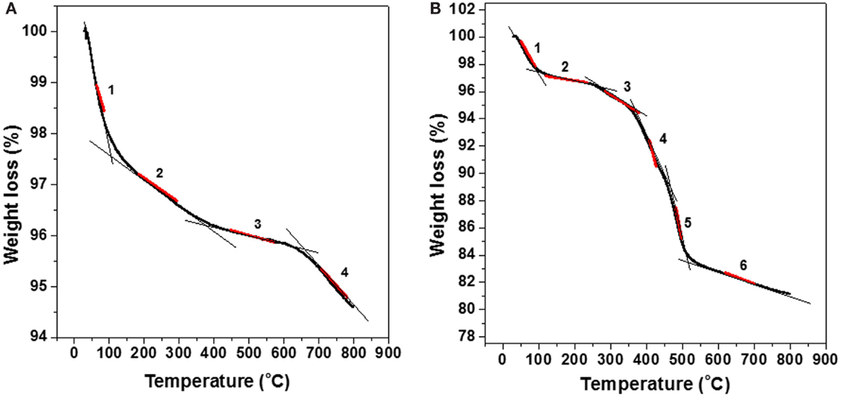
Figure 1. Thermogravimetric curve (TGA) for halloysite without dodecylamine corrosion inhibitor (A) and loaded with dodecylamine corrosion inhibitor (B).
At Figure 1B, one can find TGA results for halloysite loaded with dodecylamine inhibitor. In the thermogravimetric curve, it is possible to identify six slopes (inflection points) that can be related to different mass loss processes. It is important to stress the need for comparing both thermograms for loaded (Figure 1B) and for non-loaded (Figure 1A) halloysite. Since the clay is the same, the additional slopes or inflection points that appear in Figure 1B can be attributed to the release or degradation of the loaded organic compound, dodecylamine. From 30 to 120°C and from 150 to 250°C, the mass losses can be assigned to the loss of adsorbed water (2.5%) (slope 1) and loss of structural water (1.9%) (slope 2), respectively. Slope 3 in the range of 250–370°C could be related to the release of adsorbed dodecylamine molecules from the external walls of halloysite, which sums a mass loss of 0.8%. Slope 4 from 370 to 470°C range could be related to the release of dodecylamine molecules from the inner part of the lumen of halloysite and their thermal degradation corresponding to a significant mass loss of 6.0%. In the literature (Frost et al., 2010; Chen and Fu, 2012a,b; Liu et al., 2013), many articles report the initial release/degradation of organic compounds entrapped in inorganic structures at temperatures higher than 250°C. The very steep slope 5 starts about 470°C and goes to 530°C corresponding to a 4.8% of mass loss and can be a sum of two concomitant processes: thermal degradation of the remaining dodecylamine in the inner halloysite structure and the beginning of dihydroxylation of the halloysite clay.
The final slope 6, from 550 to 800°C is related to the dehydroxylation of AlOH groups in the clay structure. It is reasonable to infer about concomitant process after comparison of Figures 1A,B in the range 470 to 800°C. Slope 3 in Figure 1A is less abrupt than the corresponding slope 5 in Figure 1B, denoting the presence of another process besides the beginning of dehydroxylation process in slope 5 of Figure 1B. If the sum of mass losses assigned to slopes 3, 4, and 5 is calculated in Figure 1B, a good estimate of the total amount dodecylamine loaded in halloysite is obtained. In this case, the sum of 1.9, 6.0, and 4.8% reaches 12.7%. If 0.5% is discounted from the total (mass loss related to slope 3 in Figure 1A), 12.2% is obtained. This value makes sense, because in literature, a range of 5–10% of cargo is always reported for different nanocontainers (Lamaka et al., 2008; Abdullayev et al., 2009; Fix et al., 2009; Skorb et al., 2009). These findings indicate that TGA technique is a good tool to estimate the inhibitor load in such inorganic nanocontainers.
Tables 1 and 2 show the different stages of mass loss of halloysite without and with encapsulated dodecylamine corrosion inhibitor, respectively. It is possible to deduce that dodecylamine load was in the range of a maximum of 13.4 wt.% (obtained from the difference of total mass loss in the presence and in the absence of dodecylamine from Tables 1 and 2) and a minimum of 12.2 wt.%, as discussed above. These estimates are reasonable and supported by other published papers (Lamaka et al., 2008; Abdullayev et al., 2009; Fix et al., 2009; Skorb et al., 2009).
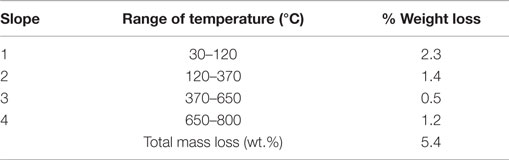
Table 1. Percentage of weight loss for different stages of thermal behavior of halloysite not loaded with dodecylamine inhibitor.
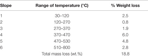
Table 2. Percentage of weight loss for different stages of thermal behavior of halloysite loaded with dodecylamine inhibitor.
Characterization of Halloysite Nanotubes by X-Ray Diffraction
Figure 2 shows the diffractograms for the samples of halloysite without and with treatment for 6 h in 2 mol/L sulfuric acid. The X-ray diffraction patterns in Figure 2 show that the samples are all dominated by halloysite [Al2Si2O5(OH)4] and also contain other minerals as impurities. Beyond halloysite, minerals as alunite (aluminum sulfate), quartz, kaolinite, and gibbsite [CaSO4.2H2O] were also found. As shown in Figure 2, natural halloysite shows a sharp peak at 2θ of 20.1°, which is the characteristic (1 1 0) peak of tubular halloysite (Bodeepong et al., 2011; Abdullayev et al., 2012; Zhang et al., 2012; Carrillo et al., 2014). No intercalation of sulfuric acid into interlayer space is observed, as the (0 0 1) reflection does not shift to lower angles. This indicates that etching of alumina takes place from halloysite lumen and proceeds toward the outermost layer (Abdullayev et al., 2012). For the halloysite treated for 6 h with 2 mol/L sulfuric acid is possible to observe an increase in the intensity of the peak corresponding to quartz (0 1 1) due to decrease of peak of halloysite (0 0 1) as consequence of the process of dealumination suffered during the treatment with sulfuric acid. Furthermore, when halloysite is treated in sulfuric acid for 6 h is possible to see that the intensity of peak (1 1 3) corresponding to alunite [KAl3(SO4)2(OH)6] increases due to a greater presence of aluminum sulfate caused by the attack provoked by sulfuric acid. In the pattern of halloysite after treatment does not appear a peak around 6°–8° that usually appears when there is adsorbed specie in the interlayer of the halloysite structure (Wilson, 2013). This could indicate that during treatment some organic species present was destroyed by treatment with sulfuric acid. Unfortunately, it was not possible to get XRD pattern of the dodecylamine-loaded halloysite that could prove the appearing of a basal interlayer peak at lower angles related to a higher basal distance (with intercalation compound) instead of that related to a peak at 10° related to a basal distance of 10 A (without intercalation compound) (Frost et al., 2010; Wilson, 2013).
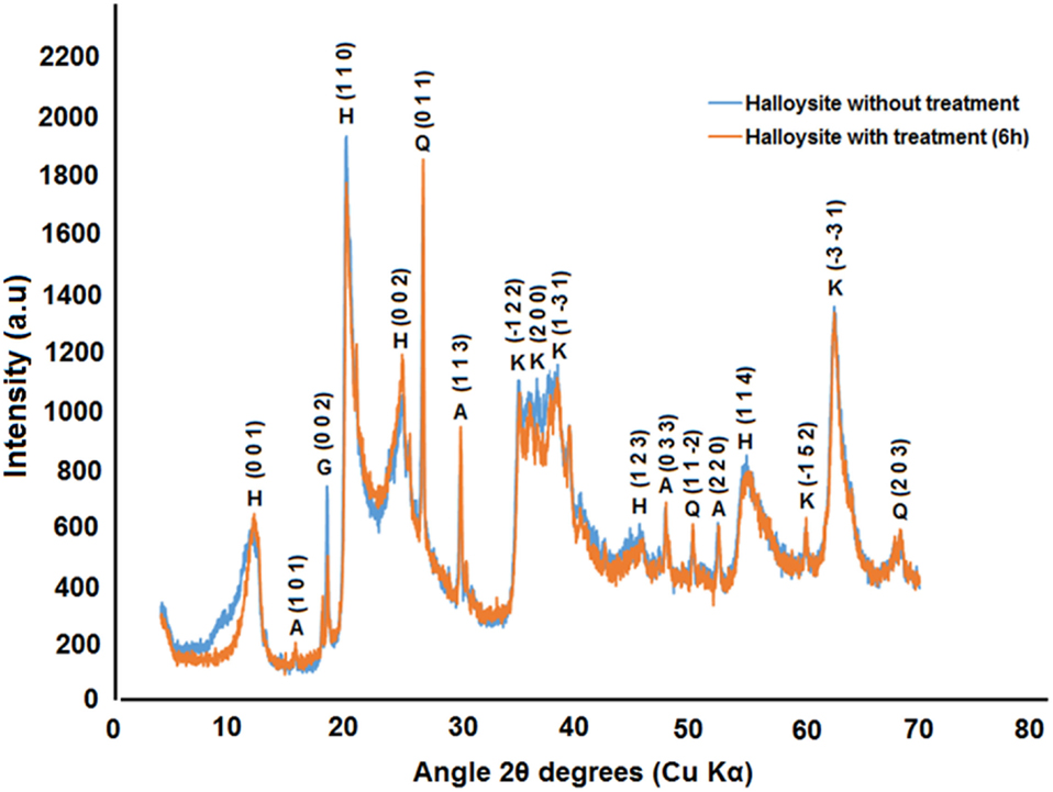
Figure 2. X-ray diffraction diffractograms of powdered samples for the halloysite without treatment and with treatment in 2 mol/L sulfuric acid during 6 h. H, halloysite; A, alunite; Q, quartz; K, kaolinite; G, gibbsite.
Kinetics of Releasing of Dodecylamine Inhibitor from Halloysite Lumen for Different Values of pH
Figures 3–5 show the impedance diagrams for carbon steel in 0.1 mol/L NaCl solution containing 1 wt.% of halloysite nanocontainers loaded with dodecylamine inhibitor after different immersion times and pH values 2.0, 6.2, and 9.0.
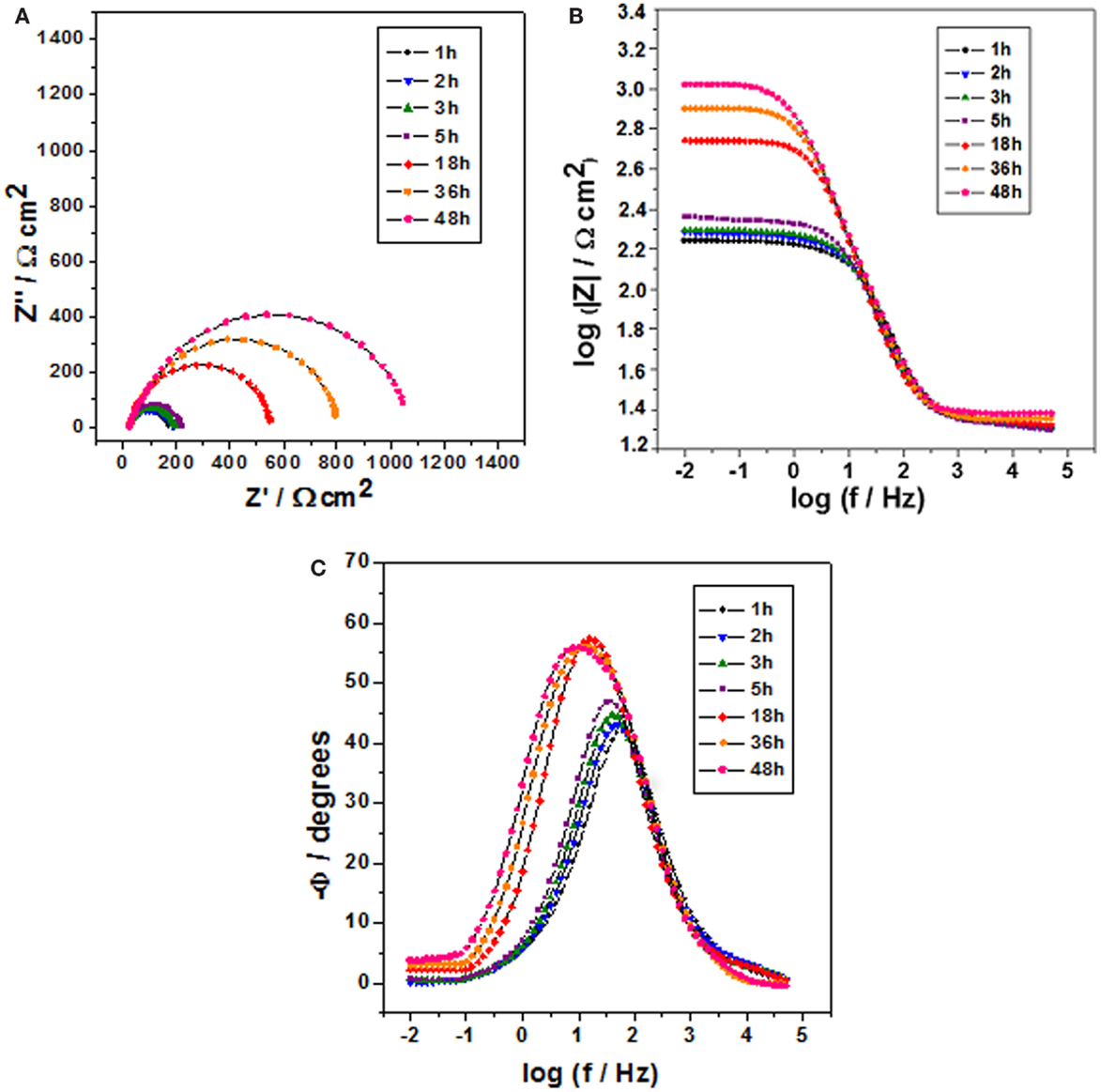
Figure 3. Impedance diagrams: Nyquist (A) and Bode (B,C) plots for carbon steel after different immersion times in 0.1 mol/L NaCl at pH 2 and containing 1 wt.% of halloysite nanotubes with encapsulated dodecylamine.
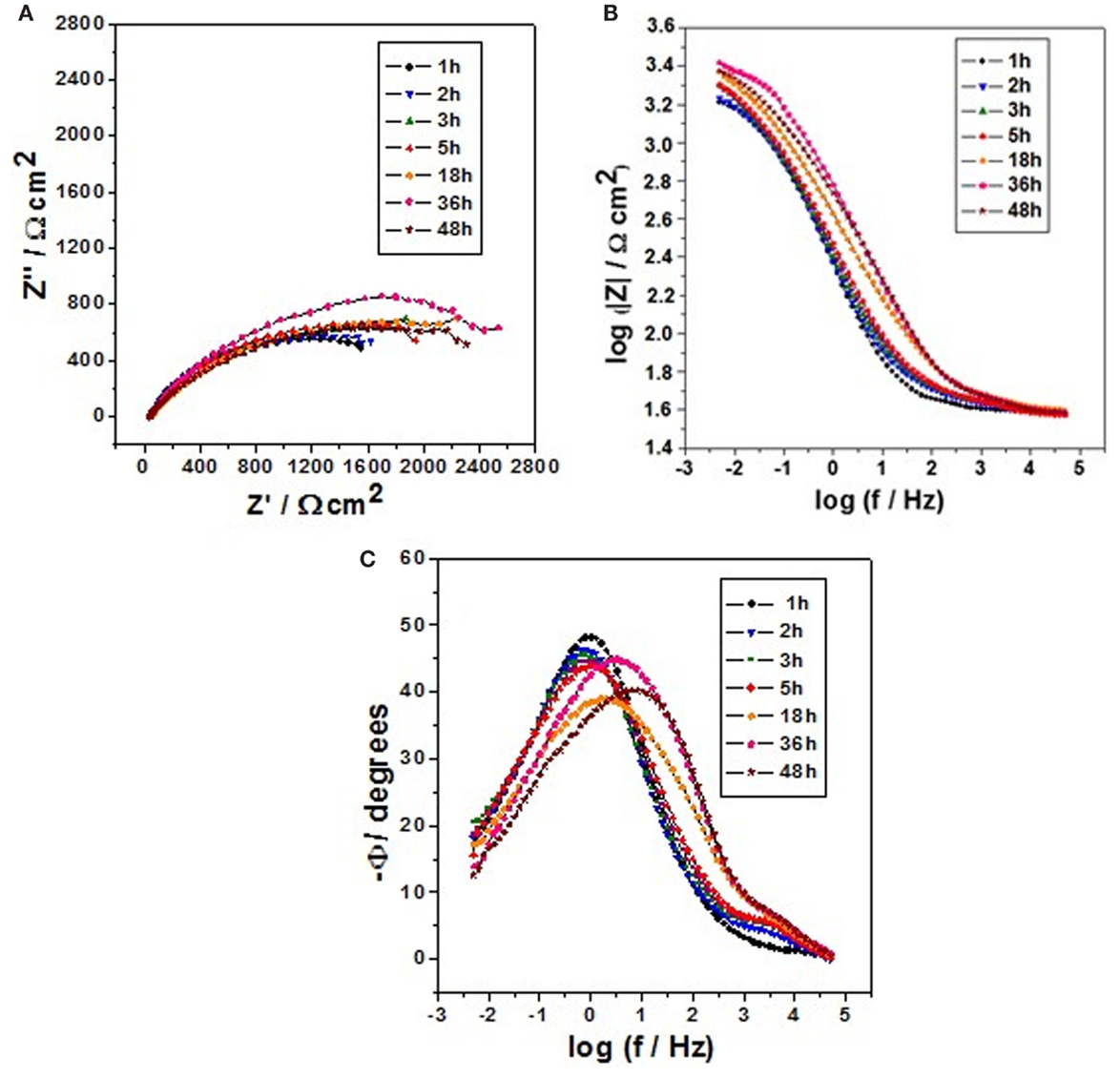
Figure 4. Impedance diagrams: Nyquist (A) and Bode (B,C) plots for carbon steel after different immersion times in 0.1 mol/L NaCl at pH 6.2 and containing 1 wt.% of halloysite nanotubes with encapsulated dodecylamine.
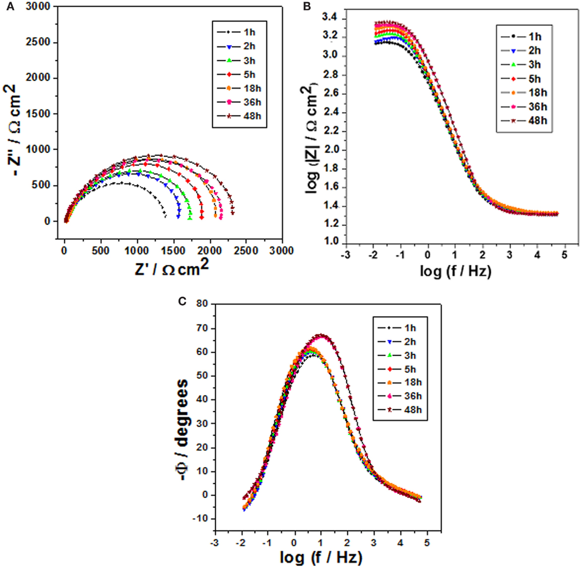
Figure 5. Impedance diagrams: Nyquist (A) and Bode (B,C) plots for carbon steel after different immersion times in 0.1 mol/L NaCl at pH 9 and containing 1 wt.% of halloysite nanotubes with encapsulated dodecylamine.
Figure 3 shows the impedance diagrams for carbon steel for various immersion times in 0.1 mol/L NaCl solution at pH 2.0 and containing 1 wt.% of HNTs loaded with dodecylamine inhibitor, where it can be observed that for initial immersion times (1, 2, 3, and 5 h), there was a small increase in the capacitive arcs diameter shown in the Nyquist diagrams whose values oscillate around 200 Ω cm2, but for long contact period (18, 36, and 48 h), this diameter increases significantly up to a value of 1100 Ω cm2, which can be confirmed in the Bode diagram (θ vs. log f) where there is a displacement of higher phase angles from higher frequencies to lower frequencies indicating a more protective character of the dodecylamine to the metal for long immersion times. These results confirm that the release of the inhibitor is accelerated at low pH after long immersion times (Zheludkevich et al., 2007; Andreeva et al., 2008) what guarantees the release of corrosion inhibitor in defective areas.
Figure 4 shows the impedance diagrams for carbon steel for different immersion times in 0.1 mol/L NaCl solution at pH 6.2 and containing 1 wt.% of HNTs loaded with dodecylamine inhibitor. In this case, is possible to observe that for short immersion times (1, 2, 3, and 5 h) the capacitive arc diameter was around 1700 Ω cm2. For longer periods of immersion (18, 36, and 48 h), a slight increase in the capacitive loop diameter till 2000 Ω cm2 can be observed. From these results, it can be conclude that for this condition of neutral pH, the inhibitor release shows a slower kinetics for longer immersion time what means that an amount of inhibitor load will last for longer time in the case of a local mechanical defect occurs, what is good scenery.
Figure 5 depicts the results of impedance for carbon steel for various immersion times in 0.1 mol/L NaCl solution at pH 9.0 and containing 1 wt.% of HNTs loaded with dodecylamine inhibitor. Similarly, for this pH, it is also possible to observe a slight increase in the capacitive arc diameter for long immersion times (18, 36, and 48 h) in comparison to the values obtained for short immersion times (1, 2, 3, and 5 h) due to a slower kinetics of release of dodecylamine from halloysite lumen what means that in this conditions the load of corrosion inhibitor will also last for longer time, shown also a good perspective, since, in a coating defect, higher pH values have been detected after long exposure time. So, if a local low pH is developed, the inhibitor will be released more slowly for short immersion times and faster for long immersion times and, if the pH is locally high, the inhibitors still will be released, but in a slower kinetics, for longer immersion times, lasting for longer periods.
Figure 6 shows the Nyquist diagrams for carbon steel after different immersion times in 0.1 mol/L NaCl at different pH values and containing 1 wt.% of HNTs without encapsulated dodecylamine. In these curves, it is possible to observe that for pH 2 condition the values of capacitive arc diameters are not constant and increase slightly until reaching a value of 475 Ω cm2. On the other hand, for the conditions of pH 6.2 and pH 9, the values of capacitive arc diameters do not present a significant increase. The values of |Z| at 31.5 mHz for each pH and different immersion time will be the reference point for the determination of the curves of corrosion inhibitor release kinetics.
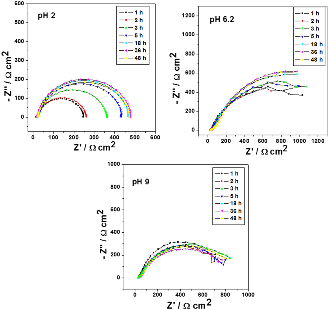
Figure 6. Impedance diagrams: Nyquist plots for carbon steel after different immersion times in 0.1 mol/L NaCl at pH 2, 6.2, and 9 and containing 1 wt.% of halloysite nanotubes without encapsulated dodecylamine.
According to results obtained in Figures 3–6 kinetic curves of dodecylamine inhibitor release from halloysite lumen were plotted for different immersion times in 0.1 mol/L NaCl solution at different pH values following the procedure explained in the Section “Materials and Methods” and are presented in Figure 7. It can be seen that for pH 6.2 and 9.0, there is a steep increase in the ratio between the impedance modulus for the condition with and without HNTs for shorter immersion times in comparison with values obtained for pH 2 and for longer immersion times a less pronounced release is noticed providing global logarithmic kinetics curves. For pH 2, the release kinetics is linear and after 48 h (high immersion times) and it is possible to observe that the release kinetics of pH 2 is very close to the release kinetics at pH 6.2 and 9.
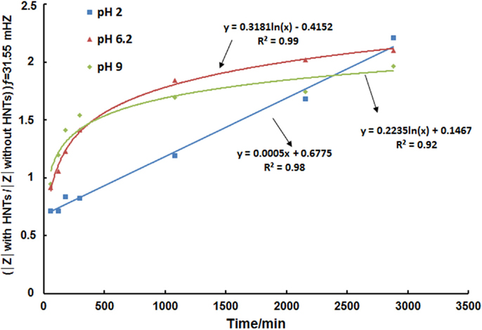
Figure 7. Curves of the kinetics of the release of encapsulated dodecylamine inhibitor from halloysite for different immersion times in 0.1 mol/L NaCl solution at different pH values.
Self-Healing Effect for Carbon Steel Samples Coated with Alkyd Primers Doped with Halloysite Nanotubes Loaded with Dodecylamine Inhibitor by EIS and SVET
EIS Measurements
The Bode diagrams (log |Z| vs. log ƒ) corresponding to the coated sample with two layers of alkyd paint containing 0 and 10 wt.% of HNTs in the primer are presented in Figures 8A,B, respectively. In both figures, it is possible to observe a capacitive response for the condition without defect, which extends from the high frequencies to the medium frequencies. HNTs cause a small decrease in impedance modulus at low frequencies. This behavior indicates that the addition of the HNTs did not affect markedly the coating barrier properties due to their good dispersion in the paint and small size, which prevented the agglomeration and allowed a more uniform distribution on the coating layers.
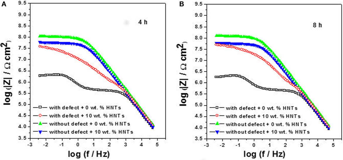
Figure 8. EIS diagrams: Bode plots for carbon steel coated with alkyd primer doped with 0 wt.% and 10 wt.% of halloysite nanotubes obtained after 4 h (A) and 8 h (B) of immersion in 0.01 mol/L NaCl.
In the case of defective coatings, it can be observed that after 4 h of immersion (Figure 8A), the addition of 10 wt.% of HNTs improved protection properties against corrosion due to the release of the inhibitor from the halloysite lumen into the damaged area. These results are in agreement with those already reported in the literature (Shchukin and Möhwald, 2007; Lvov et al., 2008; Shchukin et al., 2008; Abdullayev et al., 2013; Snihirova et al., 2013). After 8 h of immersion (Figure 8B), the coating self-healing has occurred and achieved the initial coating protective properties due to the increasing of impedance modulus values at low frequencies caused by the action of the dodecylamine inhibitor in the defect site, which provides a long and effective protection against carbon steel corrosion.
Scanning Vibrating Electrode Technique Measurements
Scanning vibrating electrode technique measurements for carbon steel coated with two layers of alkyd paint, with the primer without HNTs, for different immersion times of 1, 3, 4, and 12 h in 0.01 mol/L NaCl are shown in Figure 9. The results showed the presence of a high anodic ionic current density (383 μA/cm2) after 1 h of immersion, which decreases over time until reaching a value of ionic current density of 325 μA/cm2 after 12 h of immersion. This is due to the initial concentration of corrosion sites in a small region but over time, this region migrates along scratch causing the decrease of anodic ionic current density (Fix et al., 2009), and the precipitation of corrosion products provokes the slowdown of corrosion process as usual.
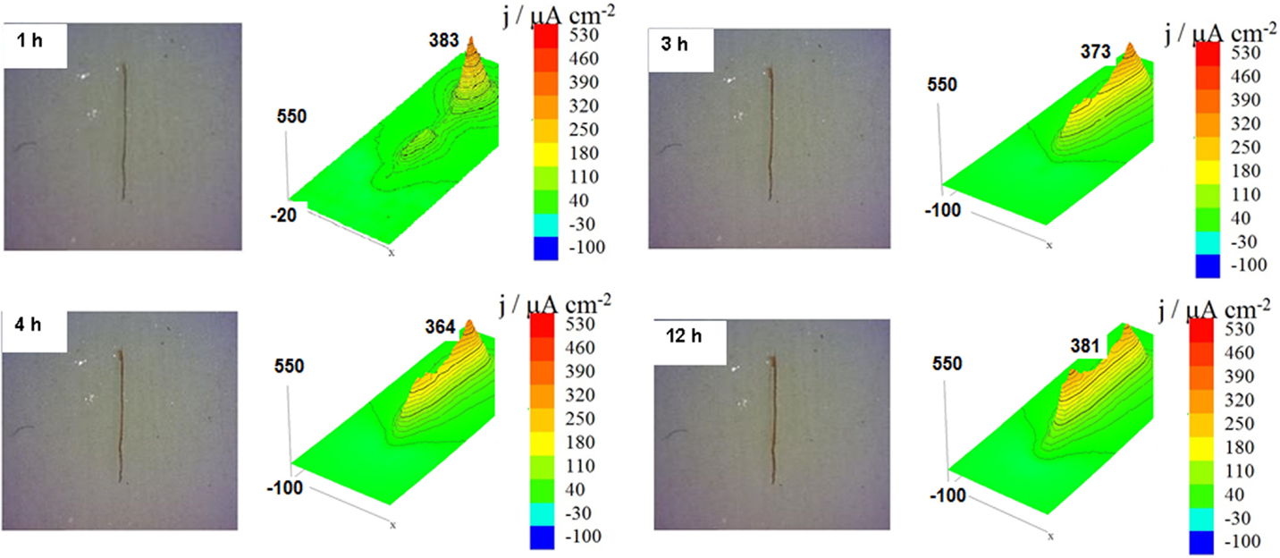
Figure 9. Scanning vibrating electrode technique maps of the ionic currents measured above the surface of the carbon steel coated with alkyd primer without halloysite nanotubes and a provoked defect obtained after different immersion times in 0.01 mol/L NaCl.
Figure 10 shows the SVET measurements and the resulting ionic current densities map obtained for carbon steel panels coated with two layers of alkyd paint and the primer containing 10 wt.% of HNTs, for different immersion times of 1, 3, 4, and 12 h in 0.01 mol/L NaCl. For these conditions, the results of SVET in Figure 10 show that initially the ionic current density values start to increase until a value of 552 μA/cm2 (after 3 h of immersion). After this time, the activity around the defect decrease sharply until reaching a value of anodic current density of only 72 μA/cm2 (4 h of immersion) showing that the corrosion process was stopped due to the action of dodecylamine inhibitor that was released from the HNTs on the provoked defect area (Lamaka et al., 2008; Lvov et al., 2008; Abdullayev et al., 2009, 2013; Fix et al., 2009; Snihirova et al., 2013). After 4 h of immersion, there was a slight decrease of the values of anodic current density until 68 μA/cm2 (12 h of immersion) and then a slight increase for 24 h of immersion (data not shown), which indicate some depletion in the amount of inhibitor released from the nanocontainers.
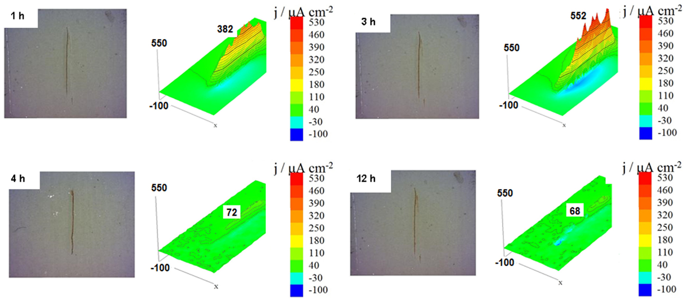
Figure 10. Scanning vibrating electrode technique maps of the ionic currents measured above the surface of the carbon steel coated with alkyd primer doped with 10 wt.% of halloysite nanotubes loaded with dodecylamine inhibitor obtained after different immersion times in 0.01 mol/L NaCl.
As the release of the corrosion inhibitor is significant at all the pHs as shown above, the corroding site locally triggers the action of entrapped inhibitor, which blocks the initial corrosion process (Lvov et al., 2008; Fix et al., 2009) and the release continues as pH is getting higher as evidenced from kinetics curves of inhibitor release in Figure 7.
Salt Spray Tests
Figure 11 presents the results obtained for coated samples in the salt spray tests for exposure times of 0 and 720 h, where it is possible to see that after 720 h a severe corrosion process is presented especially for the coated samples without halloysite. On the other hand, for the coated samples with 10 wt.% of dodecylamine-loaded halloysite (on the primer layer), there was less corrosion products and no blistering around scribe compared to coated samples without nanocontainers, indicating a better protection against ingress of aggressive species at the scribe and preventing the spread of corrosion under the paint.
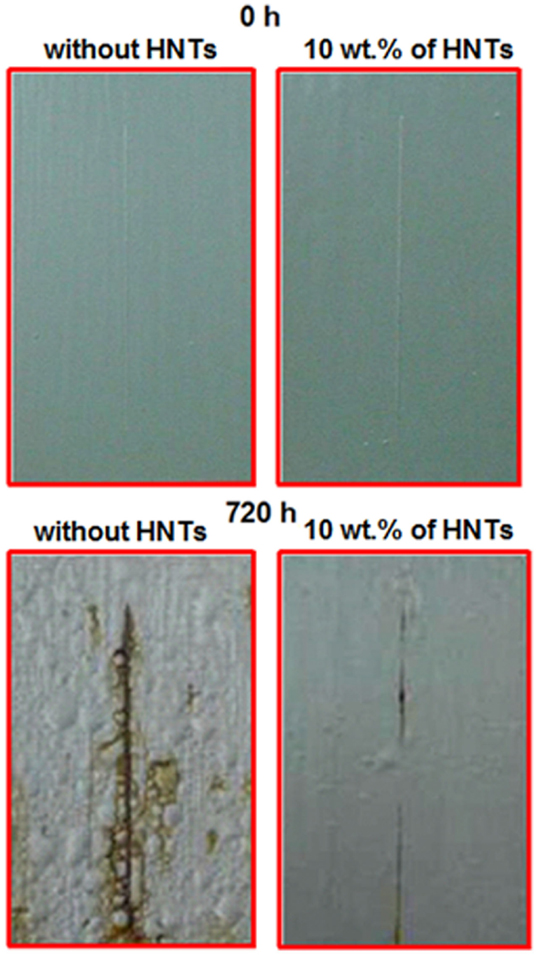
Figure 11. Aspect of coated samples with two layers of alkyd primer containing 0 and 10 wt.% of halloysite nanotubes before and after 720 h of exposure in the salt spray chamber.
Conclusion
The XRD studies showed that the halloysite sample contain other types of minerals as alunite, quartz, kaolinite, and gibbsite, which may have affected the performance of the halloysite.
Thermogravimetric curves indicated more than one simple step for the release and/or degradation of dodecylamine from halloysite structure. It was possible to estimate the amount of inhibitor loaded in the halloysite nanoclay.
Electrochemical impedance spectroscopy and SVET results for the carbon steel coated with a primer layer doped with 10 wt.% of HNTs loaded with dodecylamine inhibitor showed self-healing ability by release of the encapsulated inhibitor triggered by pH changes around provoked defect inhibiting the kinetics of corrosion process.
The salt spray tests showed that the addition of dodecylamine-loaded HNTs on the primer of coated samples provided self-healing properties, with the release of inhibitor from the lumen of halloysite inhibiting the attack provoked by the corrosion process.
These results unquestionably prove the self-healing capacity of the alkyd primer doped with halloysite loaded with dodecylamine and prescribes the possibility of enhancing the protective properties of such coating system that is well known as not the best for high performance coatings.
Conflict of Interest Statement
The authors declare that the research was conducted in the absence of any commercial or financial relationships that could be construed as a potential conflict of interest.
Funding
Authors would like to express sincere gratitude to CNPq for the financial support for developing this research (Process no. 141051/2010-08).
References
Abdullayev, E., Abbasov, V., Tursunbayeva, A., Portnov, V., Ibrahimov, H., Mukhtarova, G., et al. (2013). Self-healing coatings based on halloysite clay polymer composites for protection of copper alloys. ACS Appl. Mater. Interfaces 5, 4464–4471. doi:10.1021/am400936m
Abdullayev, E., Joshi, A., Wei, W., Zhao, Y., and Lvov, Y. (2012). Enlargement of halloysite clay nanotube lumen by selective etching of aluminium oxide. ACS Nano 6, 7216–7226. doi:10.1021/nn302328x
Abdullayev, E., Price, R., Shchukin, D. G., and Lvov, Y. M. (2009). Halloysite tubes as nanocontainers for anticorrosion coating with benzotriazole. ACS Appl. Mater. Interfaces. 1, 1437–1443. doi:10.1021/am9002028
Andreeva, D. V., Fix, D., Möhwald, H., Hack, T., and Shchukin, D. (2008). Self-healing anticorrosion coatings based on pH-sensitive polyelectrolyte/inhibitor sandwichlike nanostructures. Adv. Mater 20, 2789–2794. doi:10.1002/adma.200800705
Andreeva, D. V., Skorb, E. V., and Shchukin, D. (2010). Layer-by-layer polyelectrolyte/inhibitor nanostructures for metal corrosion protection. ACS Appl. Mater. Interfaces 2, 1954–1962. doi:10.1021/am1002712
Bodeepong, S., Bhongsuwan, D., Pungrassami, T., and Bhongsuwan, T. (2011). Characterization of halloysite from Thung Yai Distric, Nackon Si Thammarat Province, in Shouthern Thailand. Songklanakarin J. Sci. Technol. 33, 599–607. doi:10.1080/09243046.2014.915116
Borisova, D., Mohwald, H., and Shchukin, D. (2011). Mesoporous silica nanoparticles for active corrosion protection. J. Mater. Chem. 5, 1939–1946. doi:10.1021/nn102871v
Carrillo, A. M., Urruchurto, C. M., Carriazo, J. G., Moreno, S., and Molina, R. A. (2014). Structural and textural characterization of a Colombian halloysite. Rev. Mex. Chem. Eng 13, 563–571. doi:10.1016/j.clay.2009.11.029
Chen, T., and Fu, J. (2012a). An intelligent anticorrosion coating based on pH-responsive supramolecular nanocontainers. J. Nanotechnol. 23, 1–12. doi:10.1088/0957-4484/23/50/505705
Chen, T., and Fu, J. (2012b). pH-responsive nanovalves base on hollow mesoporous silica spheres for controlled release of corrosion inhibitor. J. Nanotechnol. 23, 1–8. doi:10.1088/0957-4484/23/23/235605
Evaggelos, M., Ioannis, K., George, P., and George, K. (2011). Release studies of corrosion inhibitors from cerium titanium oxide nanocontainers. J. Nanopart. Res. 13, 541–554. doi:10.1007/s11051-010-0044-x
Fix, D., Andreeva, D. V., Shchukin, D., and Mohwald, H. (2009). Application of inhibitor-loaded halloysite nanotubes in active-corrosive coatings. Adv. Funct. Mater. 19, 1720–1727. doi:10.1002/adfm.200800946
Frost, R. L., Yang, J., Hongfei, C., Liu, Q., and Zhang, J. (2010). Thermal analysis and infrared emission spectroscopic study of halloysite potassium acetate intercalation compound. Thermochim. Acta. 511, 124–128. doi:10.1007/s10973-014-3692-8
Hu, Y., Chen, Y., Zhang, L., Jiang, X., and Yang, C. (2005). Synthesis and stimuli-responsive properties of chitosan/poly(acrylic acid) hollow nanospheres. Polymer 46, 12703–12710. doi:10.1016/j.polymer.2005.10.110
Joshi, A. (2014). Applications of Halloysite Nanocontainers for Functional Protective Coating. Ph.D. thesis, Louisiana Tech University, Ruston, LA.
Joshi, A., Abdullayev, E., Vasiliev, A., Volkova, O., and Lvov, Y. (2013). Interfacial modification of clay nanotubes for the sustained release of corrosion inhibitors. Langmuir 29, 7439–7448. doi:10.1021/la3044973
Kamble, R., Ghag, M., Gaikawad, S., and Panda, B. K. (2012). Halloysite nanotubes and applications: a review. J. Adv. Sci. Res. 3, 25–29.
Lamaka, S. V., Shchukin, D., Andreeva, D. V., Zheludkevich, M. L., Möhwald, H., and Ferreira, M. G. S. (2008). Sol-gel/polyelectrolyte active corrosion protection system. Adv. Funct. Mater. 18, 3137–3147. doi:10.1002/adfm.200800630
Liu, M., Wu, C., Jiao, Y., Xiong, S., and Zhou, C. (2013). Chitosan-halloysite nanotubes nanocomposite scaffolds for tissue engineering. J. Mater. Chem. B. 1, 2078–2089. doi:10.1039/c3tb20084a
Luo, Z., Wang, A., Wang, C., Qin, W., Zhao, N., Song, H., et al. (2014). Liquid crystalline phase behavior and fiber spinning of cellulose/ionic liquid/halloysite nanotubes dispersions. J. Mater. Chem. A 2, 7327–7336. doi:10.1039/c4ta00225c
Lvov, Y. M., Aerov, A., and Fakhrullin, R. (2014). Clay nanotube encapsulation for functional biocomposites. Adv. Colloid Interface Sci. 207, 189–198. doi:10.1016/j.cis.2013.10.006
Lvov, Y. M., Shchukin, D., Mohwald, H., and Price, R. R. (2008). Halloysite clay nanotubes for controlled release of protective agents. ACS Nano 2, 814–820. doi:10.1021/nn800259q
Montemor, M. F. (2014). Functional and smart coatings for corrosion protection: a review of recent advances. Surf. Coat. Tech. 258, 17–37. doi:10.1016/j.surfcoat.2014.06.031
Nesterova, T., Dam-Johansen, K., and Kill, S. (2011). Syntheses of durable microcapsules for self-healing coatings: a comparison of selected methods. Prog. Org. Coat 70, 325–342. doi:10.1016/j.porgcoat.2010.09.032
Nicolini, K. P., Fukamachi, C. R. B., Wypych, F., and Mangrich, A. S. (2009). Dehydrated halloysite intercalated mechanochemically with urea: thermal behavior and structural aspects. J. Colloid Interface Sci. 338, 474–479. doi:10.1016/j.jcis.2009.06.058
Price, R. R., Gaber, B. P., and Lvov, Y. M. (2001). In-vitro release characteristics of tetracycline HCl, khellin and nicotinamide adenine dineculeotide from halloysite; a cylindrical mineral. J. Microencapsul. 18, 713–722. doi:10.1080/02652040010019532
Rawtani, D., and Agrawal, Y. K. (2012). Multifarious applications of halloysite nanotubes: a review. Rev. Adv. Mater. Sci. 30, 282–295.
Shchukin, D., Lamaka, S. V., Yasakau, K. A., Zheludkevich, M. L., Ferreira, M. G. S., and Möhwald, H. (2008). Active anticorrosion coatings with halloysite nanocontainers. J. Phys. Chem. C 112, 958–964. doi:10.1021/jp076188r
Shchukin, D., and Möhwald, H. (2007). Surface-engineered nanocontainers for entrapment of corrosion inhibitors. Adv. Funct. Mater 17, 1451–1458. doi:10.1002/adfm.200601226
Shi, Y. F., Tian, Z., Zhang, Y., Shen, H. B., and Jia, N. Q. (2011). Functionalized halloysite nanotube-based carrier for intracellular delivery of antisense oligonucleotides. Nanoscale Res. Lett. 6, 1–7. doi:10.1186/1556-276X-6-608
Skorb, E. V., Fix, D., Andreeva, D. V., Möhwald, H., and Shchukin, D. (2009). Surface-modified mesoporous SiO2 containers for corrosion protection. Adv. Funct. Mater 19, 2373–2379. doi:10.1002/adfm.200801804
Snihirova, D., Liphardt, L., Grundmeier, G., and Montemor, F. (2013). Electrochemical study of the corrosion inhibition ability of “smart” coatings applied on AA2024. J. Solid State Electrochem. 17, 2183–2192. doi:10.1007/s10008-013-2078-3
Suh, Y. J., Kil, D. S., Chung, K. S., Abdullayev, E., Lvov, Y. M., and Mongayt, D. (2011). Natural nanocontainer for the controlled delivery of glycerol as a moisturizing agent. J. Nanosci. Nanotechnol. 11, 661–665. doi:10.1166/jnn.2011.3194
Suryanarayana, C., Rao, K. Z., and Kumar, D. (2008). Preparation and characterization of microcapsules containing linseed oil and its use in self-healing coatings. Prog. Org. Coat. 63, 72–78. doi:10.1007/s11434-010-4133-0
Tedim, J., Poznyak, S. K., Kuznetsova, A., Raps, D., Hack, T., Zheludkevich, M. L., et al. (2010). Enhancement of active corrosion protection via combination of inhibitor-loaded nanocontainers. ACS Appl. Mater. Interfaces 2, 1528–1535. doi:10.1021/am100174t
Wilson, M. J. (2013). Rock-Forming Minerals: Sheet Silicates – Clay Minerals, 2nd Edn. London: Geological Society of London.
Wu, D. Y., Meure, S., and Solomom, D. (2008). Self-healing polymeric materials: a review of recent developments. Prog. Polym. Sci. 33, 479–522. doi:10.1016/j.progpolymsci.2008.02.001
Yuan, P., Southon, P. D., Liu, Z., Green, M. E. R., Hook, J. M., Antill, S. J., et al. (2008). Functionalization of halloysite clay nanotubes by grafting with γ-aminopropyltriethoxysilane. J. Phys. Chem. C 112, 15742–15751. doi:10.1021/jp805657t
Yuan, P., Southon, P. D., Liu, Z., and Kepert, C. J. (2012). Organosilane functionalization of halloysite nanotubes for enhanced loading and controlled release. Nanotechnology. 23, 1–5. doi:10.1088/0957-4484/23/37/375705
Yuan, P., Tan, D., and Annabi-Bergaya, F. (2015). Properties and applications of halloysite nanotubes: recent research advances and future prospects. Appl. Clay Sci. 11, 75–93. doi:10.1016/j.clay.2015.05.001
Yuan, P., Tan, D., Annabi-Bergaya, F., Yan, W., Liu, D., and Liu, Z. (2013). From platy kaolinite to aluminosilicate nanoroll via one-step delamination of kaolinite: effect of the temperature of intercalation. Appl. Clay Sci. 8, 68–76. doi:10.1016/j.clay.2015.05.001
Zhang, A. B., Pan, L., Zhang, H. L., Liu, S. T., Ye, Y., Xia, M. S., et al. (2012). Effects of acid treatment on the physic-chemical and pore characteristics of halloysite. Colloids Surf. A. 396, 182–188. doi:10.1016/j.colsurfa.2011.12.067
Zheludkevich, M. L., Serra, R., Montemor, M. F., and Ferreira, M. G. S. (2005). Oxide nanoparticle reservoirs for storage and prolonged release of corrosion inhibitors. Electrochem. Commun. 7, 836–840. doi:10.1016/j.elecom.2005.04.039
Keywords: nanocontainers, self-healing, halloysite, corrosion inhibitor, dodecylamine, smart coatings
Citation: Falcón JM, Sawczen T and Aoki IV (2015) Dodecylamine-Loaded Halloysite Nanocontainers for Active Anticorrosion Coatings. Front. Mater. 2:69. doi: 10.3389/fmats.2015.00069
Received: 27 July 2015; Accepted: 13 November 2015;
Published: 30 November 2015
Edited by:
Wolfram Fürbeth, DECHEMA-Forschungsinstitut, GermanyReviewed by:
Ole Øystein Knudsen, SINTEF and Norwegian University of Science and Technology, NorwayFlavio Deflorian, University of Trento, Italy
Copyright: © 2015 Falcón, Sawczen and Aoki. This is an open-access article distributed under the terms of the Creative Commons Attribution License (CC BY). The use, distribution or reproduction in other forums is permitted, provided the original author(s) or licensor are credited and that the original publication in this journal is cited, in accordance with accepted academic practice. No use, distribution or reproduction is permitted which does not comply with these terms.
*Correspondence: Idalina Vieira Aoki, idavaoki@usp.br