Advanced Model for Fast Assessment of Piezoelectric Micro Energy Harvesters
 Raffaele Ardito1
 Alberto Corigliano1*
 Giacomo Gafforelli1
Carlo Valzasina2
Giacomo Gafforelli1
Carlo Valzasina2
 Francesco Procopio2
Roberto Zafalon3
Francesco Procopio2
Roberto Zafalon3
- 1Department of Civil and Environmental Engineering, Politecnico di Milano, Milan, Italy
- 2AMS Group, STMicroelectronics, Cornaredo, Italy
- 3R&D and Public Affairs, STMicroelectronics, Agrate Brianza, Italy
The purpose of this work is to present recent advances in modeling and design of piezoelectric energy harvesters, in the framework of micro-electro-mechanical systems (MEMS). More specifically, the case of inertial energy harvesting is considered, in the sense that the kinetic energy due to environmental vibration is transformed into electrical energy by means of piezoelectric transduction. The execution of numerical analyses is greatly important in order to predict the actual behavior of MEMS devices and to carry out the optimization process. In the common practice, the results are obtained by means of burdensome 3D finite element analyses (FEA). The case of beams could be treated by applying 1D models, which can enormously reduce the computational burden with obvious benefits in the case of repeated analyses. Unfortunately, the presence of piezoelectric coupling may entail some serious issues in view of its intrinsically three-dimensional behavior. In this paper, a refined, yet simple, model is proposed with the objective of retaining the Euler–Bernoulli beam model, with the inclusion of effects connected to the actual three-dimensional shape of the device. The proposed model is adopted to evaluate the performances of realistic harvesters, both in the case of harmonic excitation and for impulsive loads.
1. Introduction
The application of piezoelectric materials is continuously increasing, with different possible uses of both direct (conversion of mechanical into electric energy) and inverse effects. The latter is applied in actuators, e.g., in the case of micropumps (Ardito et al., 2013) or ultrasound transducers, PMUT (Muralt and Baborowsky, 2004); on the other hand, one of the most promising application of direct effect is energy harvesting (Roundy and Wright, 2004). In recent times, the concept of energy harvesting has been applied to micro-electro-mechanical systems (MEMS), with similar functioning principles (Jeon et al., 2005; Kim et al., 2012): an additional broadening of applications can be forecast in the next future, with the immediate corollary of a fundamental need for improved computational tools. A micro energy harvester (or scavenger) is a device which transforms available energy, present in the environment (solar power, thermal energy, wind energy, or kinetic energy), into electric energy and uses it to power small devices such as wearable electronics or wireless sensor networks. The development of ultra-low-power electronic devices is a substantial spur for the development of MEMS energy harvesters, with the aim of achieving energy-autonomous sensors. In the design of a MEMS energy harvester, the big issue is that the energy generated by the harvester decreases rapidly when the size of the device reduces; hence, a trade-off between size and energy scavenged must be found. In this perspective, piezoelectric materials are advantageous because they have high energy density, and they are not too much affected by the size scaling. Piezoelectric energy harvesters (PEHs) consist of a vibrating spring-mass system coupled with a piezoelectric element, which is designed to convert elastic energy into electric energy. The common approach with MEMS PEHs consists of a piezolaminated cantilever with a large tip mass at the free edge (Roundy and Wright, 2004). The conversion of energy is achieved exploiting the so-called 31-mode of the piezoelectric thin film: the planar deformation of the piezoelectric material produces an electric field in the vertical direction. Such an electric field induces a current flow when the layer is sandwiched between electrodes and connected to an appropriate external circuit.
In a previous paper (Gafforelli et al., 2015), we developed a simple 1D model in order to simulate piezoelectric thin beams. Starting from the fully coupled 3D constitutive equations of piezoelectricity, appropriate hypotheses should be introduced to model strains and stresses so that the 1D model takes into account the 3D effects (Maurini et al., 2004, 2006). It is worth noting that such effects are really negligible if one considers the structural behavior of a beam in the absence of piezoelectric coupling. Conversely, in the case of multi-physics simulation of harvesters, the effects connected to the actual shape of the beam involve a significant variation of the results in terms of electrical quantities.
The theoretical model is founded on an enrichment of the Euler–Bernoulli kinematic field, with additional strain contributions which aims at introducing some three-dimensional effects: the obtained model is denoted as modified transverse deformation (MTD). The modification is based on the width-to-length ratio and is driven by some considerations on the 3D behavior of piezoelectric films. Such an enriched model is unprecedented, to the author’s knowledge, and allows the user to obtain reliable results in a negligible time.
In this paper, the model is applied to some specific examples referred to inertial energy harvesters, which are usually represented by cantilever beams (see Figure 1). A simple resistance R is considered in the electrical circuit attached to the piezoelectric element. The numerical solution is obtained making use of the Rayleigh–Ritz technique, with specific discretization of both the displacement and the voltage fields. The validation is obtained by the critical comparison with the results of full 3D computations. Once validated, the model of the cantilever beam can be employed for the optimal design of realistic cantilever harvesters. Two cases of realistic devices are considered: (i) energy harvester which is subject to a harmonic excitation, in resonance with the first eigenfrequency of the cantilever and (ii) PEHs in the presence of impulsive loads. Both cases are of practical interest: the former is inspired by inertial harvesting from rotating machinery; the latter can be applied in the presence of impact-induced vibration or for some specific cases of frequency-up conversion (FupC, better described in what follows).
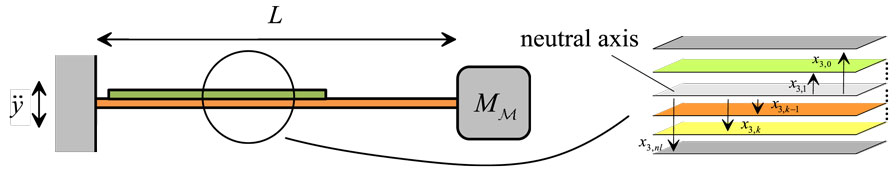
Figure 1. Schematic view of the cantilever harvester and stratification of the piezolaminated beam.
The paper is organized in this way: the proposed model is thoroughly described in Section 2; the governing equations are summarized in Section 3, which also describes the application of the Rayleigh–Ritz technique; the validation of the model is briefly revised in Section 4; and the results for the realistic devices is contained in Section 5. Finally, some conclusions and future prospects are drawn in Section 6.
2. Description of the Proposed Model
2.1. Constitutive Model for Piezoelectric Materials
Linear piezoelectric constitutive equations are a combination of classical Hooke’s law, employed in continuum mechanics, and standard linear constitutive relation between electric and strain fields. The herein adopted notation is customary in the theory of piezoelectricity (IEEE Standard on Piezoelectricity, 1987).
The peculiarity of piezoelectricity is the third order coupling tensor emij that couples mechanical and electrical quantities. These coefficients refer to three main coupling mechanisms, which are depicted in Figure 2, using the standard assumption that direction 3 is always the polarization direction:
(a) 33-mode: when applying an electric field along the polarization axis, the piezoelectric element stretches in this same direction (and vice versa);
(b) 31-mode: when applying an electric field along the polarization axis, the piezoelectric element shrinks in the orthogonal plane (and vice versa);
(c) Shear mode: when applying an electric field orthogonal to the polarization axis, a shear occurs in the element plane (and vice versa).
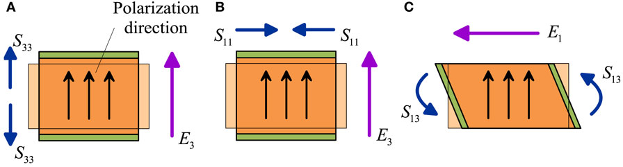
Figure 2. Piezoelectric modes using the standard assumption that direction 3 is the polarization direction: (A) 33-mode, (B) 31-mode, and (C) shear-mode.
According to the physics of piezoelectric coupling, only few coupling constants are non-zero. Indeed, e333 is related to mode (a), e311 and e322 are related to mode (b), while e113 and e223 are related to mode (c). Voigt’s notation is usually employed to represent the constitutive equations. It is, therefore, possible to use vectors for representing second-order symmetric tensors and matrices for representing third and fourth order tensors. In this way, the piezoelectric coupling matrix e reduces to the following:
In the isotropic case, the complete expression of piezoelectric constitutive law reads
In the previous equations, the following symbols are used: Tij and Sij are the second order, symmetric, stress and strain tensors, respectively; Ej is the electric field; Dj is the electric displacement field; E is the Young’s modulus; ν is the Poisson’s ratio; ehk are the components of the piezoelectric coupling matrix e, see equation (1); and (no sum) represent the dielectric permittivities of the piezoelectric material.
It is worth noting that the MEMS energy harvesters are based on piezoelectric thin film, which can be realized over a silicon substrate by means of different techniques, e.g., by means of pulsed laser deposition (Horwitz et al., 1991) or by exploiting the sol–gel procedure (Jacobsen et al., 2010). It is common practice (Trolier-McKinstry and Muralt, 2004) to derive the effective properties for piezoelectric thin films, on the basis of the bulk parameters, by imposing the suitable conditions on stress and strain components, dictated by the thin film geometry. In this work, such an operation will be carried out with reference to an improved kinematic model, as described in the next section.
2.2. Kinematic Model
The cantilever harvester is a piezolaminated beam clamped at one end section and free to oscillate on the other side. The dynamic response of the laminated beam can be easily modeled by employing standard beam theories for laminated composites. Herein, classical lamination theory (CLT) (Ballhause et al., 2005; Carrera and Ciuffreda, 2005) is employed, and the kinematics of the beam section is described through Euler–Bernoulli hypothesis (i.e., plane sections orthogonal to the neutral axis remain plane and orthogonal to the same after deformation). Generally speaking, Euler–Bernoulli hypothesis usually fails in modeling laminated beams because the shear deformation plays a fundamental, and usually non-negligible, role in describing the deformation of laminated beams. Nevertheless, if the beam is particularly thin with a limited number of layers with similar elastic properties (i.e., same order of magnitude of Young’s modulus and Poisson’s coefficient in different layers), this hypothesis can be considered valid. The reference system is centered on the neutral axis of the beam and on the clamped-in end section. The x1 axis lies along the beam’s length, so that it ranges between 0 and L; the x2 axis is along the beam’s width and ranges between −b/2 and b/2; and finally, the x3 axis is across the beam’s thickness h. The Euler–Bernoulli kinematic model, in its original form, depends on the transverse displacement w(x1) only. In this paper, we consider a suitable modification to obtain the modified transverse deformation (MTD) model. The final model, in terms of the displacement components sj, reads
The additional functions and depend on a geometric parameter Λ, which represents the transverse slenderness of the beam, i.e., the ratio of the beam’s length and the beam’s width:
The chosen model should fulfill the standard requirements for a beam theory: the in-the-thickness stress must be null, T33 = 0 and the in-plane stress must be T22 = 0 at x2 = ±b/2. The MTD model aims at obtaining a variable response for different transverse slendernesses: when Λ → 0, the beam is extremely wide and the strain condition S22 = 0 must be verified (limit situation of null transverse deformation, NTD); on the other hand, when Λ → ∞, the beam is extremely narrow and T22 = 0 has to be guaranteed (limit situation of null transverse stress, NTS). These features can be obtained if the strain component S22 is modified through the introduction of a “transversal shape function” fΛ:
where A(Λ) contains two fitting parameters, aΛ and bΛ:
The modified transverse strain is obtained starting from the expression of S22 in the NTS case; such an expression is then multiplied by the function fΛ. In that way, if Λ → ∞, then fΛ → 1 and the NTS situation is recovered; if Λ → 0, then fΛ → 0 and S22 → 0, that correspond to the NTD case. The modified transverse strain, for isotropic piezoelectric material, reads
After some algebraic manipulations (see Gafforelli et al. (2015) for details), one finds that the piezoelectric constitutive law can be written in the following form:
Strains and displacements are linked via compatibility equations, and the kinematics of the beam as proposed in equation (4) should be compatible with the strain fields. Since the interest in building a structural theory is given to strain–stress fields rather than to the displacement field, it is preferable to build structural hypotheses upon the strain field and then integrate it to obtain the displacement field. In this way, one can obtain the expressions of and . One interesting point is the computation of shear strain components on the basis of the modified displacement fields. After some algebraic manipulations, here omitted for the sake of conciseness, one finds that S13 is rigorously null on the whole beam; S23 is proportional to the thickness-to-length ratio, which is very small, so its value can be neglected; S12 is not equal to zero, but it has null mean on the cross-section since the “transversal shape function” fΛ is an even function with respect to x2. It is possible to conclude that the proposed model involves no shear contributions in the stiffness matrix, which governs the beam’s deformation.
3. Governing Equations
The governing equations for the piezoelectric problem can be obtained by using the dissipative form of Euler–Lagrange equations:
where 𝒟 is the dissipation function and ℒ is the Lagrangian function, which is given by suitably combining the kinetic energy 𝒦, the internal energy ℰ, and the external work 𝒲:
The Lagrangian coordinates qi govern the problem in its discretized form and will be introduced at the end of this section. All the functionals in equations (12) and (13) are obtained by integration over the volume of the beam: it is thus necessary to take into account the layered nature of the piezoelectric beam, so a suitable modification of the CLT should be introduced (the relevant details have been explained in Gafforelli et al. (2015)). For the computation of the internal energy, it is necessary to take into account the constitutive law described in Section 2.1. After the integration, one finds the generalized version of the governing parameters: inertia, damping and stiffness for the mechanical terms, intrinsic capacitance for the electrical terms, and the coupling parameter, which summarizes the piezoelectric effects. All these parameters, whose complete expression can be found in (Gafforelli et al., 2015), account for the layered nature of the beam (along the thickness) and for the effect of fΛ (which depends on x2, along the width).
An approximate solution is sought in the framework of the Rayleigh–Ritz procedure. First, the displacement field is expressed on the basis of a single time-variant parameter W, given a suitable shape function ψw:
Second, the electric potential is assumed to be linear across the thickness tp of the piezoelectric layer and constant along the beam length, so that the electric field is uniform:
The Lagrangian coordinates to be used in equation (12) are represented by W and V. It is worth noting the simplicity of such an approximation, which is equivalent to the application of the finite element method with a single element on the whole beam. Nonetheless, the numerical comparisons reported in the next section confirm the validity of the proposed approach.
The governing equations are finally obtained
The coefficients are obtained by means of integration through the beam’s volume: m is the total inertial term; cM is the linear mechanical damping coefficient; k is the linear elastic stiffness; CE is the internal capacitance of the piezoelectric layer; and Θ is the coupling constant. The electric charge q, collected by the electrodes, is managed by an external circuit, which provides the power supply for the self-powered electronic device. Different schemes of circuitries are investigated in Guyomar et al. (2005). The harvester provides AC voltage, and the simplest solution is the coupling with an external load resistance:
The final system of equations reads
The external force Fext can be given by different sources. For instance, one can consider the inertial forces connected to an external acceleration imposed to the whole system (ÿ in Figure 1); in that case, Fext includes the inertial effect of both the tip mass and the beam itself. A second possibility, which is investigated in Section 5.2, is represented by an impulsive force exerted at the beam’s tip.
4. Validation of the Proposed Method
The numerical validation of the proposed model has been obtained by means of critical comparisons with a 3D finite element (FE) model, which has been developed with the commercial code ABAQUS. In a preliminary stage, some simple static analyses have been used for the calibration of the parameters aΛ and bΛ; afterward, the validity of MTD hypotheses has been checked with reference to quasi-static and dynamic analyses. A simple cantilever has been adopted, with 2 layers only (2-μm PZT on 6-μm polysilicon substrate), and no tip mass is introduced. The beam’s length is L = 1000 μm; the width is parametric and varies from b = 50 to 5000 μm. The lower surface of the PZT layer is grounded, from the electric point of view, while the potential on the upper surface is constrained to be uniform in order to reproduce the presence of electrodes. After the convergence analysis, it has been possible to select the optimal FE mesh for the 3D model, which has been discretized by using brick elements with quadratic displacement fields: 40 quadratic elements along the beam axis, 10 elements in the width, and one element for each layer in the thickness.
The complete validation campaign is described in Gafforelli et al. (2015). One of the analyses which have been considered for carrying out the comparison is related to free vibration: the beam’s tip is quasi-statically moved until a certain position, and it is suddenly released. The oscillations are governed by the first natural frequency of the beam ωr and by the mechanical quality factor QM, which is inversely proportional to the damping coefficient cM. It is worth noting that the MTD model is by far less expensive, from the computational standpoint, with respect to 3D analyses: a single dynamic analysis through the solution of equation (18) lasts for 3 s, whereas the ABAQUS FE model requires more than 5 h. Nonetheless, satisfactory agreement is obtained on the oscillation frequency and amplitude. Clearly, the single-d.o.f model considered herein is able to capture only the first vibration mode, but this is, in general, sufficient for evaluating the performances of vibrating harvesters.
The analyses have been repeated by changing the resistance R and the quality factor QM, for a cantilever with fixed width equal to 200 μm. The results of parametric analyses at varying R are depicted in Figure 3A. As expected, the MTD model better reproduces numerical results than null transverse stress and deformation models. The peak power generation is underestimated at low resistances where the influence of higher modes on the voltage is higher. The effect of the mechanical quality factor on the peak power generation is reported in Figure 3B. Except for exceptionally low values of QM, the peak power generation remains more or less constant. In spite of this, the mechanical damping has a strong influence on the performances of the harvester in terms of overall harvested energy. In fact, Figure 4B shows that the total energy which is collected is reduced as QM decreases. The energy harvested is also affected by the choice of the resistance (Figure 4A). It has to be noted that the peak power generation and the peak energy harvested do not occur at the same load resistance. The peak power is reached at R = 14.4 kΩ, while the peak energy harvested is obtained at R = 8.7 kΩ. This value represents the optimal load resistance associated to free vibrations of the harvester.
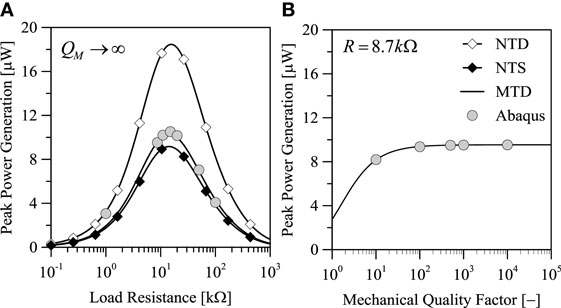
Figure 3. Influence of (A) load resistance and (B) mechanical damping on peak power generation in dynamic analyses for an impulsive tip load.
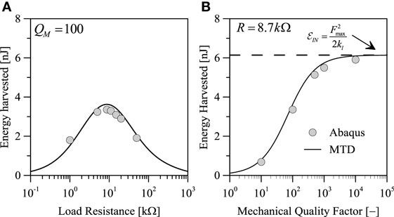
Figure 4. Influence of (A) load resistance and (B) mechanical damping on total energy harvested in dynamic analyses for an impulsive tip load.
The FE model has been used also in order to explore the validity of linear kinematics. In fact, the MTD model is based on the basic hypothesis of small strain and displacement. On the other hand, the FE analyses have been repeated after switching on the geometric non-linearity (finite strain and displacement). In that way, it has been possible to set the deformation limit until which the linear analysis can be adopted with a reasonable degree of approximation. This aspect will be treated in the next section.
5. Performance Assessment for a Realistic PEH
5.1. Harmonic Excitation
Once validated, the model of the cantilever beam can be employed for the characterization and evaluation of the performances of cantilever harvesters. Parametric analyses with different geometrical features have been performed in order to analyze the influence of the beam’s length and of the piezoelectric layer’s thickness on the harvester response.
The laminate beam is composed of several layers, as summarized in Table 1, which contains the mechanical parameters of all the layers and the piezoelectric coefficients of the active layer. The thickness of the piezoelectric film varies between 0.5 and 2 μm. The cantilever width is fixed to be b = 1000 μm, while the length of the beam varies between 400 and 2000 μm. A parallelepiped silicon mass is placed at the beam’s tip and has dimensions 200 μm × 1000 μm × 1000 μm. The mechanical quality factor is supposed to be QM = 500, which seems to be reasonable for realistic harvesters. The whole structure is subject to an external acceleration with harmonic variation:
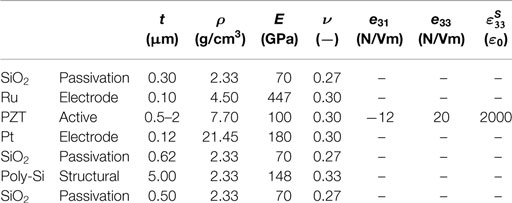
Table 1. Geometrical features and material parameters for the various layers of the cantilever MEMS harvester (listed in the correct order from top to bottom), ε0 = 8.854 × 10⁻¹² F/m.
The amplitude is A = 1 g (9.81 m/s2), and the frequency is equal to the natural frequency of the device. The parametric analyses are intended to show the influence of the beam’s geometry (length and thickness) on the response of the harvester in terms of maximum displacement and voltage in open circuit conditions; maximum power generation is at the optimal resistance.
Figure 5A shows the influence of the beam’s length on the open circuit peak displacement. The straight black line is introduced for pointing out the limit of validity of the linear model adopted herein: in fact, the preliminary FE analyses have shown that the linearized model entails a maximum relative error of 15% on displacement (with respect to non-linear geometry analyses) if the maximum oscillation of the beam’s tip does not exceed one half the beam’s length. For each value of the parameter tP, all the length’s values higher than Lmax = 2Wmax (which are highlighted through opaque rectangles) must not be considered because a non-linear model which includes finite deformations and rotations would be more appropriate. All the forthcoming plots include some “forbidden regions,” highlighted again by colored rectangles, for reminding this fact. Figure 5B shows the peak OC voltage which is in the range of 0.4 ÷ 1.5 V, while Figure 6 shows (a) the resonance and antiresonance natural frequencies, which span from 350 Hz to 1.5 kHz; (b) the resonance and antiresonance optimal load resistances, which are barely 1.4 ÷ 2.2 kΩ at resonance and span from 30 to 400 kΩ at antiresonance. Finally, Figure 7 shows the peak power generation, which is in the range of few microwatts. It is worth noting that the power generation is a non-monotonic function of tP, even though this fact cannot be appreciated in Figure 7: some extended parametric analyses prove that the maximum power is attained for tP = 0.18 μm, which is lower than the minimum thickness considered herein in view of technological constraints. The effect of a reduction of PZT thickness is explained by the fact that there is a trade-off between the increase of the oscillation amplitude, which is a consequence of lower stiffness, and the decrease of power generation, due to the lower amount of piezoelectric material.
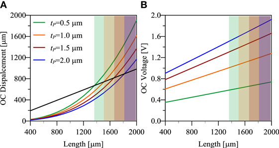
Figure 5. Open circuit peak (A) displacement and (B) voltage as a function of beam’s length and PZT thickness for a resonant cantilever harvester with QM = 500.
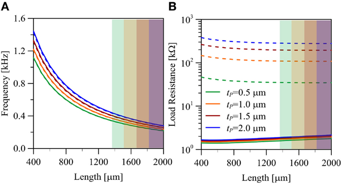
Figure 6. Resonance (solid) and antiresonance (dashed) (A) natural frequencies and (B) optimal resistances as a function of beam’s length and PZT thickness for a resonant cantilever harvester with QM = 500.
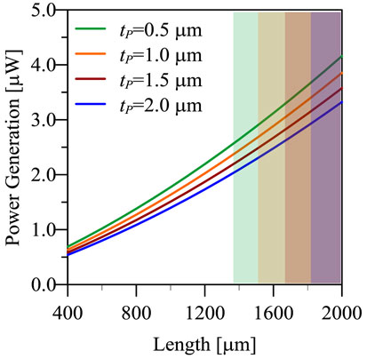
Figure 7. Peak power generation at optimal resistance as a function of beam’s length and PZT thickness for a resonant cantilever harvester with QM = 500. Maximum amplitude of external acceleration: 1 g.
These results are qualitatively and quantitatively in agreement with literature results on cantilever harvesters with dimensions similar to the ones considered herein (Muralt et al., 2009). It is worth noting that these preliminary results already show that cantilever beams of standard MEMS dimensions are not suitable for being efficiently employed as resonant energy harvesters. Indeed, although the obtained power generation can be considered useful for some applications that require few microwatts as power supply (e.g., pacemakers), this power is obtained in very strict conditions. Cantilever beam harvesters are efficient only at the resonance frequency. Unfortunately, applications where the input vibrations are monoharmonic in the useful range of frequencies are extremely rare. Clearly, it is extremely inefficient to use such harvesters with random and low-frequency vibrations because the resonance regime cannot be obtained. For that reason, many authors in recent years spent a lot of efforts in looking for solutions to overcome frequency matching limitation, which is inherent in linear harvesters. For instance, the frequency band can be extended by exploiting the non-linear mechanical behavior, as attempted by Gafforelli et al. (2014). Another possible solution to overcome this problem is frequency-up conversion (FupC), which aims at the realization of a mechanical interface between the low-frequency excitation and the high-frequency vibration mode of the harvester. FupC can be achieved in different ways, for instance, by means of magnetic contactless interaction (Tang et al., 2011) or by exploiting the snap-through instability of special mechanical devices (Cottone et al., 2012). In many cases, if FupC is applied, then an impulsive action is exerted on the piezoelectric beam: that case is studied in the next section.
It is worth reminding that the previous analyses have been done fixing the mechanical quality factor to 500. From a general point of view, the quality factor of an energy harvester should be as high as possible in order to improve the performances of the system, because high QM means high displacements and high deformation to be transduced. However, the maximum displacement must be compatible with the device design, and the deformation must be sustainable for the materials. This consideration basically means that in high-QM harvesters the stiffness should be high enough to exclude unsustainable deformations, and this ends up in small and stiff devices with high resonance frequency. As an example, the reader should consider the previous cantilever beam with a quality factor of 3000 instead of 500. As shown by Figure 8, for a given length the power generation is higher than that of high damping harvesters. However, the useful range of lengths is much smaller than in the previous case.
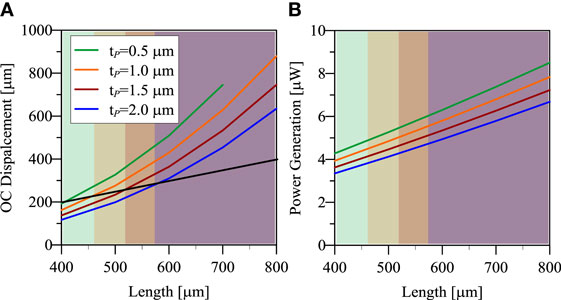
Figure 8. (A) Open circuit peak displacement and (B) power generation as a function of beam’s length and PZT thickness for a resonant cantilever harvester with QM = 3000.
5.2. Impulsive Excitation
Cantilever piezoelectric beams are not only used as resonant energy harvesters but are also part of non-linear harvesters that consider jump phenomena or implement frequency-up-conversion. From a general point of view, such devices implement techniques that impulsively stimulate the piezoelectric beams, which then execute the energy conversion.
At this stage, the focus is more on the evaluation of the performances of the piezoelectric beam rather than the design of frequency conversion techniques. Similar to what has been done with resonant cantilever beams, parametric analyses have been performed in order to highlight the influence of the beam’s geometry on the conversion of energy under impulsive solicitations. The parametric study has been performed using the same cantilever beam used for resonant harvesters, but in this case, no seismic mass is provided at the free edge of the beam. The mechanical quality factor is again QM = 500. The cantilever has been initially submitted to a smooth step load (Fmax = 1 μN/μm), followed by a sudden jump to zero. In this way, the beam is free to oscillate until the unperturbed configuration is reached again. The external load resistance is supposed to be designed such that the harvester works at its optimum; it is possible to demonstrate that the optimal performances, in terms of energy, are obtained when Ropt = (CEωr)−1. It is worth reminding that the maximum peak power would be obtained at a value, which is roughly 1.7 times Ropt.
The peak displacement (Figure 9A), the peak voltage (Figure 9B), and the peak power generation (Figure 10A) are obtained just after the beam is released. Their values depend on the maximum value of the applied force and on the harvester elastic, piezoelectric, and electric characteristics. For this reason, their values are considerably affected by the type of model chosen to describe the beam behavior. Herein, the modified transverse deformation theory (MTD) has been used in order to correctly reproduce the beam behavior for the whole range of width–length ratios. As a result, the peak voltage and the peak power generation are not perfectly linear with respect to the length. It is worth noting that the maximum displacement is much lower than the one obtained for the same beam employed in resonant harvesters. This actually means that the piezoelectric beam is not employed at its maximum performances with this type of solicitation, and the harvester performances can be further increased.
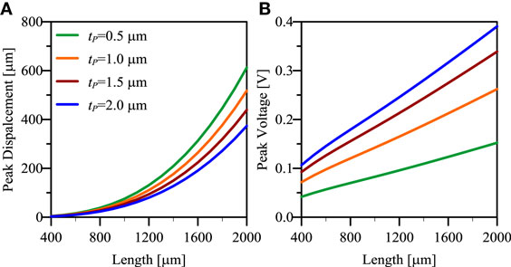
Figure 9. (A) Peak displacement and (B) peak voltage as a function of beam’s length and PZT thickness for an impulsive cantilever harvester.
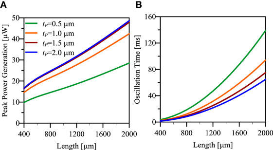
Figure 10. (A) Peak power generation and (B) total oscillation time as a function of beam’s length and PZT thickness for an impulsive cantilever harvester.
The duration of the oscillation (τosc, Figure 10B) depends on the beam’s geometry, in particular on the resonance frequency and on the damping (mechanical and electrically induced). The oscillations are arbitrarily truncated when the peak displacement is less than 1/100 of the initial displacement. Figure 11A reports the total energy harvested in this time lapse, whereas Figure 11B shows the mean value of power generation computed as the total energy divided by the oscillation time. In this case, the influence of the mechanical damping on the response is different than for resonant harvesters. Indeed, the peak displacement, power, and voltage are not much affected by the value of damping as already shown in Section 4. On the contrary, the value of damping significantly affects the oscillation time and the total energy harvested, which will be equal to the all injected elastic energy in the hypothetical case of null mechanical damping.
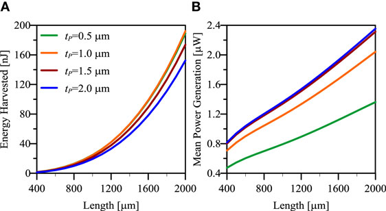
Figure 11. (A) Total energy harvested and (B) mean power generation as a function of beam’s length and PZT thickness for an impulsive cantilever harvester.
Figure 12 reports the influence of PZT thickness on the device performances for a beam length of 1000 μm. The figures show that the maximum energy harvested is obtained when tP = 0.7 μm, while the maximum peak and mean power are obtained when tP = 1.9 μm.
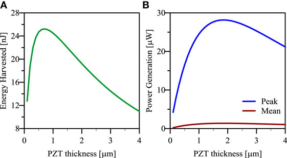
Figure 12. (A) Total energy harvested and (B) peak (blue) and mean (red) power generation as a function of PZT thickness for an impulsive cantilever harvester with length equal to 1000 μm.
6. Conclusion and Future Prospects
The present paper is focused on parametric analyses of realistic MEMS PEHs, with the main purpose of pointing out the most important features to be considered in the design phase. The analyses have been carried out in the time domain (step-by-step analyses), and the computational burden has been substantially reduced by using the MTD model. In that way, a simple one-d.o.f. can be adopted without any loss in terms of accuracy. The proposed model can be improved by the introduction of non-linear kinematics, in order to simulate also the cases of large oscillations. Moreover, the design procedure of real PEH deserves a more detailed study of mechanical damping and of other possible external circuits (e.g., RLC circuits, non-linear electric behavior, etc.).
Two possible operation modes of PEHs have been considered. Power generation in resonant harvesters is directly proportional to the beam’s width and length, but a non-monotonic dependence on the PZT thickness has been highlighted. The peak power can reach reasonable levels, but that happens only in resonance conditions, with non-negligible displacements and high excitation frequency. For instance, resonant PEHs with L = 1300 μm, b = 200 μm, and tP = 0.5 μm can produce a peak power Pmax = 2.4 μW, if the load resistance is R ≈ 1.5 kΩ and the excitation frequency is fr = 360 Hz. Resonant MEMS harvester are reasonable only for high-speed rotating machinery, without any possible application in case of human-induced or environmental vibrations.
On the other hand, the cantilever piezoelectric beam shows good performances when impulsively solicited, possibly in conjunction with a FupC device. Remarkable peak power generation can be obtained (more than 25 μW in the example of Figure 12), and the mean power generation is comparable to the one of a resonant harvester with the important advantage of being uncoupled from the source frequency. Moreover, the performances can be further increased if one considers the full deformation capability of the beam subject to higher forces. The major issue regards the technique how the impulsive force is applied. In case the applied force has a limit value which cannot be overcome (this might be due to external conditions such as the input acceleration content or the maximum transferable force of the frequency-up conversion mechanism), the beam’s length must be designed in order to assure the maximum performances of the harvester.
Author Contributions
RA – supervisor of reduced order modeling. AC – supervisor of the whole research activity. GG – developed the 1D model and FE simulations. CV – supervisor of the industrial applications. FP – developed the model for industrial applications. RZ – supervisor of the funding project.
Funding
The authors wish to thank the ENIAC Joint Undertaking, Key Enabling Technology, project Lab4MEMS, Grant no. 325622, for partial funding of this research.
Conflict of Interest Statement
The authors declare that the research was conducted in the absence of any commercial or financial relationships that could be construed as a potential conflict of interest.
References
Ardito, R., Bertarelli, E., Corigliano, A., and Gafforelli, G. (2013). On the application of piezolaminated composites to diaphragm micropumps. Compos. Struct. 99, 231–240. doi: 10.1016/j.compstruct.2012.11.041
Ballhause, D., D’Ottavio, M., Kröplin, B., and Carrera, E. (2005). A unified formulation to assess multilayered theories for piezoelectric plates. Comput. Struct. 83, 1217–1235. doi:10.1016/j.compstruc.2004.09.015
Carrera, E., and Ciuffreda, A. (2005). A unified formulation to assess theories of multilayered plates for various bending problems. Compos. Struct. 69, 271–293. doi:10.1016/j.compstruct.2004.07.003
Cottone, F., Gammaitoni, L., Vocca, H., Ferrari, M., and Ferrari, V. (2012). Piezoelectric buckled beams for random vibration energy harvesting. Smart Mater. Struct. 21, 035021. doi:10.1088/0964-1726/21/3/035021
Gafforelli, G., Corigliano, A., and Ardito, R. (2015). Improved one-dimensional model of piezoelectric laminates for energy harvesters including three dimensional effects. Compos. Struct. 127, 369–381. doi:10.1016/j.compstruct.2015.02.065
Gafforelli, G., Corigliano, A., Xu, R., and Kim, S.-G. (2014). Experimental verification of a bridge-shaped, nonlinear vibration energy harvester. Appl. Phys. Lett. 105, 203901. doi:10.1063/1.4902116
Guyomar, D., Badel, A., Lefeuvre, E., and Richard, C. (2005). Toward energy harvesting using active materials and conversion improvement by nonlinear processing. IEEE Trans. Ultrason. Ferroelectr. Freq. Control 52, 584–595. doi:10.1109/TUFFC.2005.1428041
Horwitz, J., Grabowski, K., Chrisey, D., and Leuchtner, R. (1991). In situ deposition of epitaxial PbZrxTi(1–x) O3 thin films by pulsed laser deposition. Appl. Phys. Lett. 59, 1565–1567. doi:10.1063/1.106284
Jacobsen, H., Prume, K., Wagner, B., Ortner, K., and Jung, T. (2010). High-rate sputtering of thick PZT thin films for MEMS. J. Electroceram. 25, 198–202. doi:10.1007/s10832-010-9615-6
Jeon, Y., Sood, R., Jeong, J.-H., and Kim, S.-G. (2005). MEMS power generator with transverse mode thin film PZT. Sens. Actuators A Phys. 122, 16–22. doi:10.1016/j.sna.2004.12.032
Kim, S.-G., Priya, S., and Kanno, I. (2012). Piezoelectric MEMS for energy harvesting. MRS Bull. 37, 1039–1050. doi:10.1557/mrs.2012.275
Maurini, C., Pouget, J., and Dell’Isola, F. (2004). On a model of layered piezoelectric beams including transverse stress effect. Int. J. Solids Struct. 41, 4473–4502. doi:10.1016/j.ijsolstr.2004.03.002
Maurini, C., Pouget, J., and Dell’Isola, F. (2006). Extension of the Euler-Bernoulli model of piezoelectric laminates to include 3D effects via a mixed approach. Comput. Struct. 84, 1438–1458. doi:10.1016/j.compstruc.2006.01.016
Muralt, P., and Baborowsky, J. (2004). Micromachined ultrasonic transducers and acoustic sensors based on piezoelectric thin films. J. Electroceram. 12, 101–108. doi:10.1023/B:JECR.0000034004.99355.8b
Muralt, P., Marzencki, M., Belgacem, B., Calame, F., and Basrour, S. (2009). Vibration energy harvesting with PZT micro device. Procedia Chem. 1, 1191–1194. doi:10.1016/j.proche.2009.07.297
Roundy, S., and Wright, P. K. (2004). A piezoelectric vibration based generator for wireless electronics. Smart Mater. Struct. 13, 1131–1142. doi:10.1088/0964-1726/13/5/018
Tang, Q. C., Yang, Y. L., and Li, X. (2011). Bi-stable frequency up-conversion piezoelectric energy harvester driven by non-contact magnetic repulsion. Smart Mater. Struct. 20, 125011. doi:10.1088/0964-1726/20/12/125011
Keywords: piezoelectric materials, energy harvesting, MEMS, lamination theory, frequency-up conversion
Citation: Ardito R, Corigliano A, Gafforelli G, Valzasina C, Procopio F and Zafalon R (2016) Advanced Model for Fast Assessment of Piezoelectric Micro Energy Harvesters. Front. Mater. 3:17. doi: 10.3389/fmats.2016.00017
Received: 01 February 2016; Accepted: 27 March 2016;
Published: 19 April 2016
Edited by:
Ettore Barbieri, Queen Mary University of London, UKReviewed by:
Francesco Dal Corso, University of Trento, ItalyJames Bowden, University of Nottingham, UK
Copyright: © 2016 Ardito, Corigliano, Gafforelli, Valzasina, Procopio and Zafalon. This is an open-access article distributed under the terms of the Creative Commons Attribution License (CC BY). The use, distribution or reproduction in other forums is permitted, provided the original author(s) or licensor are credited and that the original publication in this journal is cited, in accordance with accepted academic practice. No use, distribution or reproduction is permitted which does not comply with these terms.
*Correspondence: Alberto Corigliano, alberto.corigliano@polimi.it