Compression ignition engines – revolutionary technology that has civilized frontiers all over the globe from the industrial revolution into the twenty-first century
 Stephen A. Ciatti
- Argonne National Laboratory, Energy Systems Division, Center for Transportation Research, Argonne, IL, USA
The history, present and future of the compression ignition engine, is a fascinating story that spans over 100 years, from the time of Rudolf Diesel to the highly regulated and computerized engines of the twenty-first century. The development of these engines provided inexpensive, reliable, and high-power density machines to allow transportation, construction, and farming to be more productive with less human effort than in any previous period of human history. The concept that fuels could be consumed efficiently and effectively with only the ignition of pressurized and heated air was a significant departure from the previous coal-burning architecture of 1800s. Today, the compression ignition engine is undergoing yet another revolution. The equipment that provides transport, build roads and infrastructure, and harvests the food we eat needs to meet more stringent requirements than ever before. How successfully twenty-first century engineers are able to make compression ignition engine technology meet these demands will be of major influence in assisting developing nations (with over 50% of the world’s population) achieve the economic and environmental goals they seek.
Introduction and Brief History of Compression Ignition Engines
Ever since Rudolf Diesel invented the internal combustion engine that would eventually bear his name, compression ignition has been utilized as an effective and efficient means to initiate combustion in engines. Diesel used vegetable oils to invent his new engine, since there was no petroleum infrastructure for fuels at that time. High-compression ratio to create the pressure and temperature required for auto-ignition was a hallmark of the compression ignition engine. A mechanism to directly inject fuel in to the combustion chamber was also required. As time progressed, an infrastructure of petroleum distillates became available for fuels such as gasoline (to support spark ignition engines), kerosene and fuel oil (heating homes), and of course, diesel fuel (Heywood, 1988).
The advantages to using compression ignition and direct injection of fuel into the combustion chamber evidenced themselves over the next few decades of its development. The compression ignition engine inherently needs a high-compression ratio to create the necessary conditions for auto-ignition. High-compression ratio is one design characteristic to improve efficiency. In addition, the compression ignition needed no throttling to control the power output of the engine. Direct injection of the fuel into the combustion chamber provided high resistance to knock, which limits the compression ratio and ultimately, the efficiency of spark ignition engines. An additional advantage is that, without any knock limitation, compression ignition engines can have generous intake pressure boosting by turbocharging, further increasing efficiency and power density.
Along the way, many technological hurdles were encountered and overcome – such as the ability to fabricate pistons and cylinder heads that could robustly achieve the high-compressions ratios needed for diesel auto-ignition, prechambers that could leverage the relatively low-pressure injectors available into the high-compression ratio full combustion chamber, new fuel injection technology with very high-pressure fuel to eliminate the need for prechambers and allow direct injection into the combustion chamber, and finally, electronic controls and actuators to provide much more precise fuel, air, and emissions controls to meet the stringent demands of emissions regulation.
Current State of Compression Ignition Engines
Compression ignition engines are used in a variety of commercial and consumer applications around the world, powering devices like large ships, locomotives, commercial trucks, construction and farm equipment, power generators, and even automobiles. Almost exclusively, these applications utilize diesel fuel for combustion. A diesel engine relies upon the ease of auto-ignition of the fuel, a chemical property engineers call cetane number/index – an empirically derived metric that describes the ease of auto-ignition of the fuel. Biodiesels are also used in many applications, especially in rural areas and in developing countries. Biodiesels are generally made from vegetable oils that have been chemically processed to remove glycerin products, leaving a fatty acid methyl (or ethyl) ester (FAME). Biodiesels attempt to mimic the properties of diesel fuel and, while they can be used as a neat fuel substitute, they are generally used as a blending agent with petroleum diesel.
There are two primary approaches to the compression ignition engine – the two-stroke and the four-stroke architecture. Very large CI engines (ship and locomotive, in particular) tend to be two-stroke, primarily because the engine speed is limited to low-revolutions per minute (RPM). Two-stroke CI engines must have an external source of air supply, such as a turbocharger or supercharger (or a hybrid of both in some cases) because the air is forced into the cylinder via ports in the cylinder liner. Figure 1 shows this configuration. The exhaust is either expelled through a different set of ports (spark ignited version) or through poppet valves in the cylinder head (see Figure 1). The intake air ports in the cylinder liner open when the piston falls below them in the power stroke, allowing pressurized, cool air into the cylinder. As the piston heads toward BDC in the power stroke, the exhaust valves in the cylinder head begin to open and the hot exhaust begins to leave the cylinder via the top-mounted exhaust valves. As the piston continues to head toward BDC, the intake ports in the cylinder liner open, allowing fresh air into the cylinder, which forces the last of the exhaust out the top exhaust valves. This scavenging process continues until the exhaust valves close (sometime around the piston position at BDC). The intake ports are still open, so fresh air continues into the cylinder from the blower, until the piston passes the top of the intake ports on the liner, trapping the air in the cylinder. Then, this air is heated and pressurized until the piston is near TDC. The fuel injector creates a high-pressure spray into the hot, compressed air, causing auto-ignition and combustion. The cycle then begins anew.
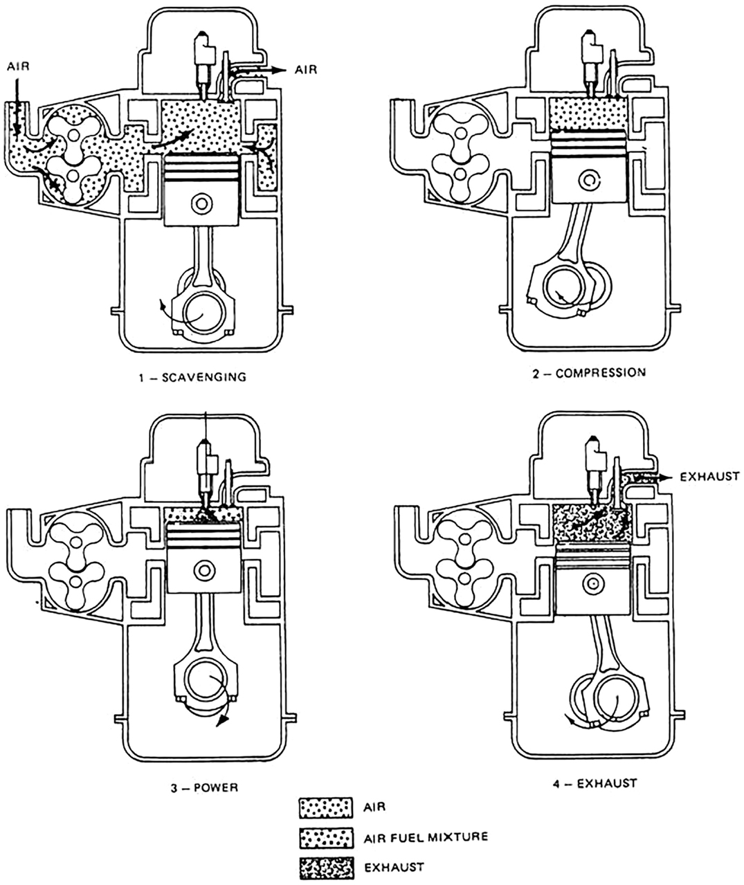
Figure 1. Schematic of a two-stroke compression ignition engine. Image taken from http://enginemechanics.tpub.com/14081/css/14081_23.htm.
On the other hand, a four-stroke compression ignition engine works by inducting air from the intake manifold into the cylinder during the intake stroke, TDC to BDC (see Figure 2), then the intake valves close and the piston then moves back toward TDC while compressing the air to elevated temperature and pressure. The injector sprays fuel into the combustion chamber, ignition occurs and the piston is forced downward at high pressure due to combustion in what is called the power stroke. Finally, the exhaust valves open and the piston returns to TDC and forces the exhaust combustion products out in the exhaust stroke. The cycle then repeats from here.
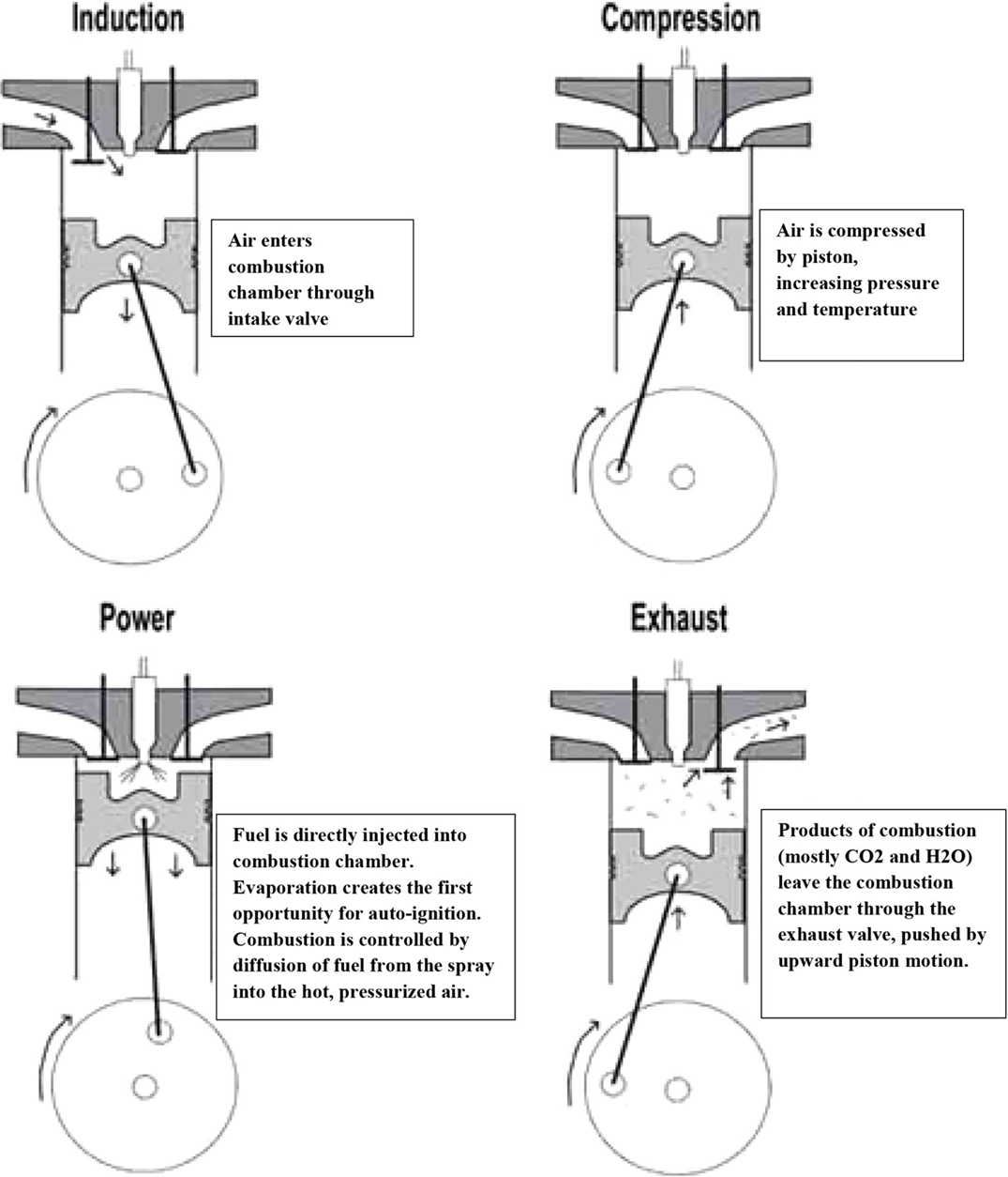
Figure 2. Schematic of four-stroke compression ignition engine. Image taken from http://vegburner.co.uk/dieselengine.html.
Regardless of whether the engine is two- or four-stroke, the intent is to create high-pressure and high-temperature air near the end of the compression portion of the cycle. The injected fuel is then exposed to the high-pressure and high-temperature air and auto-ignites very rapidly. The delay between the injection of fuel and the auto-ignition is called as the ignition delay, which is typically a few crank angles. Fuel continues to be injected as a jet, which has a reaction zone on the periphery of the jet and the reaction is controlled by the diffusion of air into the reaction zone coupled with the diffusion of fuel outward to the reaction zone. This diffusion process occurs in milliseconds, while the actual reactions occur on the microsecond timescale, so the fluid mechanics of diffusion are controlling the rate of reaction.
Significant research effort has been expended to study pathways to improve the efficiency, emissions signature, reliability, and power output of CI engines. Manufacturing companies, universities, and research laboratories have all lent their expertise, equipment, and facilities to advancing CI engine technology. Some of these advancements include direct injection (DI) to eliminate the need for prechambers and reduce heat transfer, optical diagnostics to study pollutant formation in-cylinder, advanced computational simulation capabilities to predict and optimize CI engine performance, significant effort to understand fuel chemistry and composition to tailor CI engine operation to locally available fuels. As engineers and scientists continue to apply their expertise to the fundamental study of CI engine technology, there is little doubt that additional advancements will be achieved.
How is the CI Engine Different from the SI Engine?
There are several reasons that CI engines are so popular in commercial and industrial applications. One important reason is the inherent fuel efficiency of CI engines is higher than that of SI engines. The nature of compression ignition provides a few important factors that allow for high-fuel efficiency. One factor is high-compression ratio (Gill et al., 1954). Since CI engines rely upon fuel injected into the cylinder and the mixing of this fuel with the air, engine knock is avoided. Engine knock is one of the primary limitations to higher compression ratio in SI engines. The second factor is the eliminated need for throttling the engine to control power output. Again, because the fuel is directly injected and mixed in the combustion chamber, the CI engine power can be controlled merely by adjusting the amount of fuel that is injected, unlike SI engines where the fuel and air are premixed and essentially homogeneous at a constant mixture ratio (Heisler, 1999). This means that to keep that mixture ratio constant, if fuel is reduced, the air must also be reduced in the same proportion. This managing of air is done with a throttle, or intake restriction, and it creates significant gas exchange or “pumping” losses. The third factor is heat transfer. CI engines are able to run “fuel lean” meaning that the engine consumes all of the fuel but not all of the oxygen present in the combustion chamber. This tends to produce lower in-cylinder temperatures and as a result, lower heat rejection to the engine coolant and engine exhaust and higher efficiency. As an additional benefit, the gamma, or ratio of specific heats Cp/Cv is higher for lean burn engines than for engines that operate at stoichiometry. Less of the thermal energy generated by the combustion reactions is lost in the excitation states of larger triatomic species (CO2 and H2O vapor). This means that more of the thermal energy is available to raise the pressure and temperature of the working fluid, which is what creates work that can be extracted (Foster, 2013).
However, there are also several drawbacks to the CI engine that are worthy of mention. The CI engine must be engineered to be very robust to handle the elevated pressures and temperatures created by high-compression ratios and boosted intake pressures. This produces engine designs that have high-rotational inertia and subsequently limits the maximum engine speed. It also elevates the cost, since all of the hardware must be very durable. Another drawback to CI engines is the emissions signature. The reliance upon diffusion controlled combustion means that there is significant stratification between the fuel and air, as opposed to the homogeneity of gasoline/air mixtures in SI engines. This stratification creates particulate matter (PM) and oxides of nitrogen (NOx). These undesired products of CI combustion have been discovered to be a health hazard and environmentally harmful. In essence, the traditional CI engine does not have an efficiency problem, it has an emissions problem.
What about Bio-Derived Fuels?
Much of the current and foreseeable work in CI engines appears to focus upon the use of alternative fuels or even multiple fuels in an effort to retain the high efficiency (perhaps even improve it) yet significantly reduce the harmful emissions signature and greenhouse gas production. Bio-derived fuels are one popular approach, especially in developing economies, to counter the greenhouse gas challenge and the cost of petroleum imports. Biofuels are generally made from some type of vegetable oil and chemically processed to create a product that mimics petroleum diesel in many ways. Several feedstocks have been utilized in this manner, depending upon the local growing conditions and the crops that thrive under those conditions. Soybeans, canola, palm seed, jatropha, and karanja oils among many others have been processed as fuels. Generally, biofuels of this type are separated into categories, those oils derived from edible plants and those derived from non-edible plants. Chemically, the fuel derived from edible plants is easier and lower cost to process into fuels. However, this can also create a “food or fuel” challenge in the local economy. Non-edible plant-derived biofuels are more difficult and expensive to process but tend to avoid the “food or fuel” difficulty. One challenge to traditional biodiesel fuel is that the fuel itself contains oxygen as part of its structure. This oxygenated-fuel will have significantly reduced energy content compared to petroleum diesel. Energy content reductions are generally on the order of 7–8% by volume compared to petroleum diesel. This leads to more volume of fuel consumed for the same amount of energy delivered. More recent work has been done with regard to algae-derived or algal fuels, which offer the potential for much larger yield than traditional biofuels (Frashure et al., 2009). Another recent research topic is the creation of “renewable” diesel from the hydrothermal or other processing of biomass material to extract long-chain hydrocarbons similar to petroleum diesel fuel (Aatola et al., 2008). Renewable diesel does not tend to be oxygenated, so the energy content tends to be the same as for petroleum diesel. Yet, another approach to creating diesel fuel from both renewable and non-renewable sources utilizes a process called Fischer–Tropsch (FT), so-called after the German inventors of this process in 1930s. FT fuels are derived from methane, gasified coal, or gasified biomass to create long-chain hydrocarbons suitable for use as fuel. Several acronyms are used for this type of fuel, depending upon the feedstock. Gas-to-liquid (GTL), coal-to-liquid (CTL), and biomass-to-liquid (BTL) are a few of these acronyms. The FT process creates quite high quality diesel fuel – high-cetane rating, low viscosity, no sulfur, and high-energy content – but the process is also complicated and expensive, at least at the present time (Agarwal, 2004).
What is State-of-the-Art for CI Engines?
CI engines are utilized worldwide as sources of motive and stationary power. As emerging economies such as India and China ramp up their demand for transport and electrical power to meet economic demand, there are serious questions regarding the future of CI engines in the face of increasingly stringent environmental regulation, greenhouse gas regulation, and demand for fossil fuel. Are there strategies that will allow the CI engine to evolve to meet these present and future market demands?
Using traditional diesel fuel, engineers have made some exciting advances in efficiency improvement and emissions reduction by employing advanced injection technology like common rail high-pressure pumps, piezo-actuated fuel injectors, advanced turbomachinery and waste heat recovery (thermoelectrics, etc.), and near-elimination of sulfur in diesel fuel. Fuel can now be much more precisely metered into the combustion chamber to create combustion events that are smoother and less polluting. The use of exhaust gas recirculation (EGR) has allowed engineers to reduce the oxygen concentration of the intake air, providing lower peak combustion temperatures with significant NOx reductions. Advances in aftertreatment, such as diesel particulate filters (DPF), deNOx catalysts (both selective catalytic reduction and lean trap), and diesel oxidation catalysts (DOC), are currently utilized in modern CI engines.
Ongoing advanced combustion work has generated exciting opportunities into the improvement of CI engine efficiency as well as significant improvement in the emissions signature. As research progresses, it has been shown that enhancing some premixing of fuel and air, while retaining the ability to control power output by fuel delivery (no throttling) and retain high-compression ratio is possible. There are a variety of strategies that have been employed to accomplish these goals. One is the use of dual fuel, popularly known as reactivity controlled compression ignition (RCCI). In RCCI, a low-reactivity fuel (such as gasoline, ethanol, or similar) is injected into the combustion chamber as the primary source of energy and a very small amount of a high-reactivity fuel (such as diesel, biodiesel, etc.). This not only allows for the ability to run the engine lean, which reduces peak combustion temperatures and improves efficiency, but also provides a positive ignition strategy to avoid misfires and retain high robustness. RCCI in research engines has demonstrated the opportunity to achieve very high levels of efficiency (primarily due to even further reduced heat transfer than traditional diesel combustion) and control robustness. The primary disadvantage to RCCI is the requirement of two injectors per cylinder (one for each fuel) and the requirement to either carry two separate fuels or carry a reactivity enhancing additive for the low-reactivity fuel (Curran et al., 2013).
Another exciting opportunity in the world of CI engines is the use of a fairly low-reactivity fuel (gasoline, naphtha, etc.) compared to diesel but still use a compression ignition architecture engine and utilize the long ignition delay of these fuels to provide some level of premixing while still retaining enough stratification to provide load control (Kalghatgi et al., 2007). Gasoline compression ignition (GCI) or partially premixed compression ignition (PPCI) attempt to achieve the same goal as RCCIs use of dual fuel but to do so by stratifying one fuel in a precise manner. This ignition control can be quite challenging compared to RCCI, since it depends upon the ever-changing local fuel/air mixing characteristics rather than positively adding a high-reactivity fuel at a certain time. The advantage is that only one fuel is required and one injector per cylinder.
In each of the cases for RCCI and PPCI, the intent is to allow enough premixing to occur for the PM levels to be low and to operate the combustion lean or dilute enough to maintain peak combustion temperatures below 2000K, avoiding thermal NOx production. The robustness of these new approaches to combustion and ignition is a challenge that is being approached by several research organizations around the world (Johansson et al., 2014; Sellnau et al., 2014).
What Does the Future Hold for CI Engines?
At least as of 2015, CI engines hold a dominant position in the commercial vehicle and off-highway vehicle markets. As more regulatory pressure is applied worldwide to greenhouse gas emissions and air quality, CI engines will continue to evolve to meet these pressures. The combination of the high-energy density of liquid fuels coupled with the high-power density of CI engines and very low cost of manufacture will continue to make CI engines a popular solution for motive and stationary power production. Exciting research has been ongoing in this field to improve efficiency, reduce emissions, improve emissions control aftertreatment technology, and tremendous progress has been made. Even more progress is needed, however, as the world’s population heads past 7 billion people and the demand for power in developing countries skyrockets. How we solve transportation and power challenges in the next few decades will set the tone for our ability as a society to maintain both a habitable environment and a standard of living that is acceptable to an ever-increasing population worldwide.
Conflict of Interest Statement
The author declares that the research was conducted in the absence of any commercial or financial relationships that could be construed as a potential conflict of interest.
Acknowledgments
The submitted manuscript has been created by UChicago Argonne, LLC, Operator of Argonne National Laboratory (“Argonne”). Argonne, a U.S. Department of Energy Office of Science laboratory, is operated under Contract No. DE-AC02-06CH11357. The U.S. Government retains for itself, and others acting on its behalf, a paid-up non-exclusive, irrevocable worldwide license in said article to reproduce, prepare derivative works, distribute copies to the public, and perform publicly and display publicly, by or on behalf of the Government. This does not affect the rights of others to re-publish and re-distribute under CC-BY terms (www.creativecommons.org). The author would like to acknowledge the financial support of the Department of Energy Office of Vehicle Technologies, Advanced Engine Combustion Program, managed by Mr. Gurpreet Singh.
References
Aatola, H., Larmi, M., Sarjovaara, T., and Mikkonen, S. (2008). Hydrotreated Vegetable Oil (HVO) as a Renewable Diesel Fuel: Tradeoff between Nox, Particulate Emission and Fuel Consumption of a Heavy Duty Engine. SAE Technical Paper 2008-01-2500. Warrendale, PA: Society of Automotive Engineers.
Agarwal, A. K. (2004). Development and Characterization of Biodiesel From Non-Edible Vegetable Oils of Indian Origin. SAE 2004-28-0079. Warrendale, PA: Society of Automotive Engineers.
Curran, S., Hanson, R., Wagner, R., and Reitz, R. (2013). Efficiency and Emissions Mapping of RCCI in a Light-Duty Engine. SAE Technical Paper 2013-01-0289. Warrendale, PA: Society of Automotive Engineers.
Foster, D. E. (2013). Available at: http://www.sae.org/events/gim/presentations/2013/foster_dave.pdf
Frashure, D., Kramlich, J., and Mescher, A. (2009). Technical and Economic Analysis of Industrial Algal Oil Extraction. SAE Technical Paper 2009-01-3235. Warrendale, PA: Society of Automotive Engineers.
Gill, P., Smith, J., and Ziurys, E. (1954). Fundamentals of Internal Combustion Engines, 4th Edn. Annapolis, MD: U.S. Naval Institute.
Johansson, B., and Gehm, R. (2014). Available at: http://articles.sae.org/12892/
Kalghatgi, G. T., Risberg, P., and Ångström, H. E. (2007). Partially Pre-Mixed Auto-Ignition of Gasoline to Attain Low Smoke and Low NOx at High Load in a Compression Ignition Engine and Comparison with a Diesel Fuel. SAE Technical Paper 2007-01-0006. Warrendale, PA: Society of Automotive Engineers.
Keywords: diesel engine, diesel fuel, compression ignition engine, gasoline compression ignition, RCCI, PPC, PPCI, biodiesel
Citation: Ciatti SA (2015) Compression ignition engines – revolutionary technology that has civilized frontiers all over the globe from the industrial revolution into the twenty-first century. Front. Mech. Eng. 1:5. doi: 10.3389/fmech.2015.00005
Received: 24 March 2015; Accepted: 31 May 2015;
Published: 24 June 2015
Edited by:
Robert Wagner, Oak Ridge National Laboratory, USACopyright: © 2015 Ciatti. This is an open-access article distributed under the terms of the Creative Commons Attribution License (CC BY). The use, distribution or reproduction in other forums is permitted, provided the original author(s) or licensor are credited and that the original publication in this journal is cited, in accordance with accepted academic practice. No use, distribution or reproduction is permitted which does not comply with these terms.
*Correspondence: Stephen A. Ciatti, Argonne National Laboratory, Energy Systems Division, Center for Transportation Research, 9700 South Cass Avenue, Building 362, Room C229, Argonne, IL 60439, USA, sciatti@anl.gov