Impact of cylinder deactivation on active diesel particulate filter regeneration at highway cruise conditions
 Xueting Lu1
 Chuan Ding2
 Aswin K. Ramesh1
 Gregory M. Shaver1*
Eric Holloway1
Gregory M. Shaver1*
Eric Holloway1
 James McCarthy Jr.3
Michael Ruth4
Edward Koeberlein4
Douglas Nielsen3
James McCarthy Jr.3
Michael Ruth4
Edward Koeberlein4
Douglas Nielsen3
- 1Ray W. Herrick Laboratories, Department of Mechanical Engineering, Purdue University, West Lafayette, IN, USA
- 2The Mathworks, Boston, MA, USA
- 3Valvetrain Engineering, Eaton, Marshall, MI, USA
- 4Cummins Technical Center, Columbus, IN, USA
Heavy-duty over-the-road trucks require periodic active diesel particulate filter regeneration to clean the filter of stored particulate matter. These events require sustained temperatures between 500 and 600°C to complete the regeneration process. Engine operation during typical 65 mile/h highway cruise conditions (1200 rpm/7.6 bar) results in temperatures of approximately 350°C, and can reach approximately 420°C with late fuel injection. This necessitates hydrocarbon fueling of a diesel oxidation catalyst or burner located upstream of the diesel particulate filter to reach the required regeneration temperatures. These strategies require increased fuel consumption, and the presence of a fuel-dosed oxidation catalyst (or burner) between the engine and particulate filter. This paper experimentally demonstrates that, at the highway cruise condition, deactivation of valve motions and fuel injection for two or three (of six) cylinders can instead be used to reach engine outlet temperatures of 520–570°C, a 170–220°C increase compared to normal operation. This is primarily a result of a reduction in the air-to-fuel ratio realized by reducing the displaced cylinder volume through cylinder deactivation.
1. Introduction
Diesel particulate filters (DPFs) have been used in all medium- and heavy-duty engines in North America since 2007 in order to meet strict EPA 0.01 g/hp hr particulate matter emissions levels. During normal operation, particulate matter generated by the engine is trapped within the DPF. In modern systems, both passive and active regeneration strategies are required to periodically remove the particulate matter from the filter. Active regeneration is achieved through oxidation of the particulate matter with oxygen at temperatures of 500–600°C, which is rarely realized at the engine outlet during normal operation (Stanton, 2013). Since the engine outlet temperatures are typically much lower (for instance, approximately 350°C at a typical 65 mile/h highway cruise condition of 1200 rpm/7.6 bar), DPF inlet temperatures in excess of 500°C are typically achieved through fuel-dosing of a diesel oxidation catalyst (Joshi et al., 2006; Singh et al., 2006) or burner upstream of the DPF, often in addition to engine-specific thermal management strategies. Electric heaters have also been considered, with little success (Breuer et al., 1996; Bach et al., 1998). The drawbacks of these approaches are twofold: (i) they require an additional component (fuel doser, burner, diesel oxidation catalyst, or electric heater) and (ii) the consumption of fuel for something other than generating engine shaft work.
The aforementioned engine-specific thermal management strategies can be classified as being based on either the “fuel path” or “air path” (Gehrke et al., 2013). Through the air path, turbine outlet temperatures can be increased by reducing the airflow through the engine (Mayer et al., 2003). In engines with a waste-gate turbocharger, this can be achieved by partially opening the wastegate (Bouchez and Dementhon, 2000). Through the fuel path, fuel injection timing can be delayed to increase engine outlet temperatures (van Nieuwstadt et al., 2003; Parks et al., 2007) via delayed main injection or late cycle post injection.
Cylinder deactivation (CDA) is another “air path” method that can be used to increase exhaust temperatures in lean burn engines by reducing the air–fuel ratio (AFR). CDA has been extensively studied as a method for efficiency improvement in spark ignited (SI) engines and is implemented in several production vehicles (Heywood and Welling, 2009). CDA implemented in SI engines reduces the amount of throttling required at low loads to maintain stoichiometric conditions, enabling a reduction in pumping penalty. However, few studies have been conducted regarding the use of CDA in diesel engines as a method for improving fuel economy or aftertreatment thermal management (Foster et al., 2005; Edwards et al., 2010; Ding et al., 2015).
A GT-Power study at 1500 rpm and 2 bar brake mean effective pressure (BMEP) conducted by Edwards et al. (2010) simulated the deactivation of a single cylinder in a GM 1.9-L light duty diesel engine by eliminating fuel injection, and leaving the intake and exhaust valves open and closed, respectively, throughout the cycle. The exhaust temperature increased by 15°C. Brake specific fuel consumption (BSFC) increased by 4%. The increase in fuel consumption was attributed to increased heat transfer and the residual friction losses in the deactivated cylinder.
Foster et al. (2005) simulated CDA using a GT-Power model of a six-cylinder compression ignition engine equipped with a turbocharger operating at 1800 rpm and a BMEP of 9 bar. The results showed that deactivating three of the six cylinders increased exhaust gas temperatures at the exit of the turbocharger by 290°C. The authors concluded that these increased temperatures could be used to improve NOx absorption, NOx reduction, diesel particulate trap purging, and desulfation of a NOx absorber.
Several authors of the present study illustrated in prior work (Ding et al., 2015) that cylinder deactivation can be used to achieve an improvement in the engine exhaust temperature and fuel consumption tradeoff at loaded and lightly loaded idle conditions (800 rpm/0.26 bar and 800 rpm/2.5 bar, respectively) through increases in open and closed cycle efficiencies.
1.1. Focus of this Study
The efforts described in the remainder of this paper focus on fuel economy and exhaust thermal management of a turbocharged multi-cylinder diesel engine utilizing cylinder deactivation at a 1200 rpm/7.6 bar highway cruise condition. The emphasis is on the cruise conditions given the significant amount of time that heavy, over-the-road trucks spend at this operating condition. It will be shown that the deactivation of two or three cylinders can be used to reach engine outlet temperatures of 520–570°C at the highway cruise condition; thereby, enabling the elimination of the hydrocarbon dosing of an oxidation catalyst or burner to reach the required filter-inlet regeneration conditions. This is a result of a reduction in the air-to-fuel ratio realized by reducing the displaced cylinder volume through cylinder deactivation.
2. Experiment Setup
The experimental test bed used in this study is a six-cylinder direct injection diesel engine outfitted with high pressure cooled exhaust gas recirculation (EGR), a variable geometry turbine (VGT) turbocharger, an air-to-water charge air cooler (CAC), and a common rail injection system (as shown in Figure 1). Kistler 6067C and AVL QC34C in-cylinder pressure transducers in tandem with an AVL 365C crankshaft position encoder are used with an AVL 621 Indicom module for high-speed indicating data acquisition. Fresh air flow is measured with a laminar flow element (LFE). Two channels of a Cambustion NDIR Fast CO/CO2 analyzer are utilized, with one in the intake manifold and the other in the exhaust pipe. Also used are California Analytical Instruments NDIR, HFID, and chemiluminescence analyzers for exhaust CO2, total unburned hydrocarbons, and NOx, respectively. A wide-band O2 sensor and an AVL 483 photo-acoustic transient particulate matter analyzer are also instrumented in the exhaust pipe.
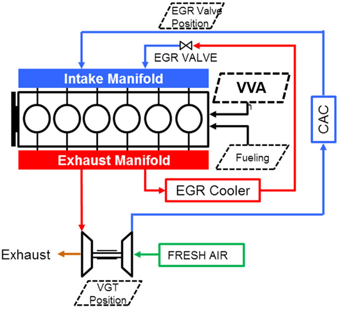
Figure 1. Schematic of experimental test-bed engine.
The multi-cylinder test bed is outfitted with a fully flexible electro-hydraulic VVA system that enables cylinder-independent, cycle-to-cycle control of the engine’s valve events. Figure 2 illustrates the operating principle of the VVA system. Each intake and exhaust valve pair are driven by the VVA system, such that it is possible to change the valve opening timing, valve closing timing, valve lift, and the ramp rates/velocity of the profiles on a cycle-to-cycle basis. High pressure hydraulic fluid powers the system. The servo valve position determines the pressure difference between the upper and lower face of the piston actuator. The piston actuator acts directly on the crosshead and actuates a valve pair. Linear variable differential transformers (LVDT) are integrated into the piston actuator and are used to provide feedback signals, which allow the valves to be controlled to a desired profile.
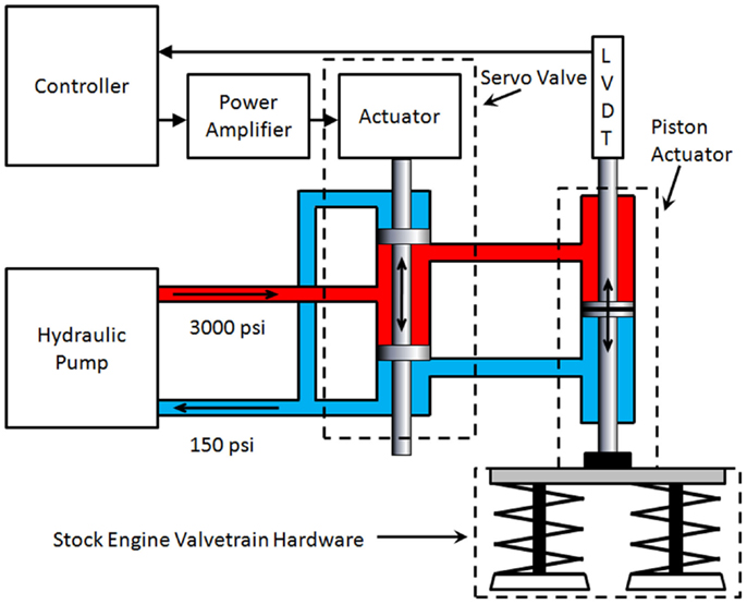
Figure 2. Schematic of the variable valve actuation system.
Valve control algorithms were developed in MATLAB/Simulink and are communicated with the VVA system through a dSPACE system in real time. Both intake and exhaust valve profiles were monitored and adjusted to match the desired profiles.
3. Methodology and Terminology
All experimental data shown, and discussed in the following sections, were subject to emissions and mechanical constraints in order to ensure relevance.
Engine-out emissions limits were used for NOx, unburned hydrocarbon (UHC), and particulate matter (PM) emissions. These limits are consistent with meeting tailpipe (e.g., post aftertreatment components) limits with modern aftertreatment (DOC, DPF, and SCR systems), as shown in Table 1. The PM limit was exceeded for two of the nine operating cases considered (details to follow in the next section).

Table 1. Emission limits.
Mechanical limits for turbine inlet temperature, turbocharger speed, compressor outlet temperature, peak cylinder pressure, cylinder pressure rise rate, and exhaust manifold pressure were also set to avoid damage to any engine component, as shown in Table 2.
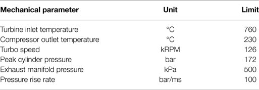
Table 2. Mechanical constraints.
The trade-offs between exhaust temperature and fuel consumption were determined for both conventional six-cylinder and cylinder-deactivated operation through modulation of fuel injection timing, rail pressure, EGR valve position, and VGT turbocharger position. Deactivation of two cylinders (two deactivated cyl.) was realized by deactivating fueling and valve motions for two of the six cylinders. Likewise, deactivation of three cylinders (three deactivated cyl.) was realized by deactivating fueling and valve motions for three of the six cylinders. The range of engine parameters considered is summarized in Table 3. The spacing between the pilot and main pulse and pilot fueling amount was kept the same as the stock engine calibration.
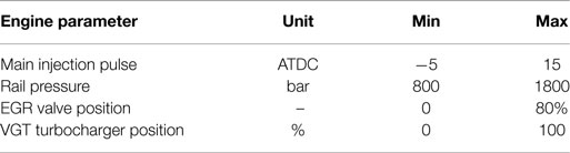
Table 3. The range of engine parameters.
Cycle efficiency analysis was used to understand the impact of CDA. The brake thermal efficiency (BTE) of the engine is the product of closed cycle efficiency, open cycle efficiency, and mechanical efficiency [as per equation (1)]. Closed cycle efficiency is impacted by combustion completeness, piston expansion work, and in-cylinder heat transfer. Open cycle efficiency quantifies the efficiency of the gas exchange and is impacted by turbine and compressor efficiency, and pressure differences between the intake and exhaust manifold. Mechanical efficiency captures losses from friction and parasitic loads. See Stanton (2013) for a detailed introduction to closed, open, and mechanical efficiencies.
4. Experimental Results
Figure 3 demonstrates that cylinder deactivation allows an improved turbine outlet temperature vs. BSFC trade-off for exhaust aftertreatment thermal management. Specifically, cylinder deactivation enables turbine outlet temperatures of 520–550°C, which is hot enough to actively regenerate a DPF without fuel-dosing a DOC or burner. In contrast, 420°C is the highest temperature possible when all six cylinders are deactivated, even when late in-cylinder main fuel injection is used.
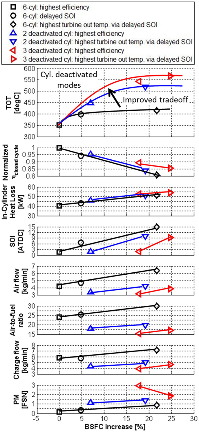
Figure 3. Result comparison for six cylinder, three deactivated, and two deactivated cylinder operation at the highway cruise condition.
Figure 3 shows that at the highway cruise condition, the lowest BSFC is achieved when all six cylinders are activated. This is in contrast to improved efficiencies with cylinder deactivation at lower loads (≤ approximately 2.5 bar) (Magee, 2013; Ding et al., 2015). The 7–18% higher minimum BSFC with cylinder deactivation at the cruise condition is a result of the larger amounts of fuel which must be injected into the activated cylinders to maintain the same engine load by increasing the activated per-cylinder work as shown in Figure 4. As shown in Figure 5, increases in injected fuel mass result in a larger injection interval causing spread out, delayed heat release, both of which decrease the closed cycle efficiency (second sub-plot in Figure 3). The fact that cylinder deactivation decreases the fuel economy of the engine during the highway cruise condition is not a surprise, as the stock six-cylinder engine is optimized/calibrated with a significant emphasis on the highway cruise condition.
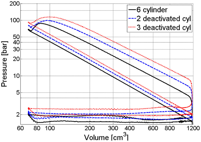
Figure 4. Pressure–volume diagram comparison for most efficient six-cylinder, three deactivated cylinder, and two deactivated cylinder modes.
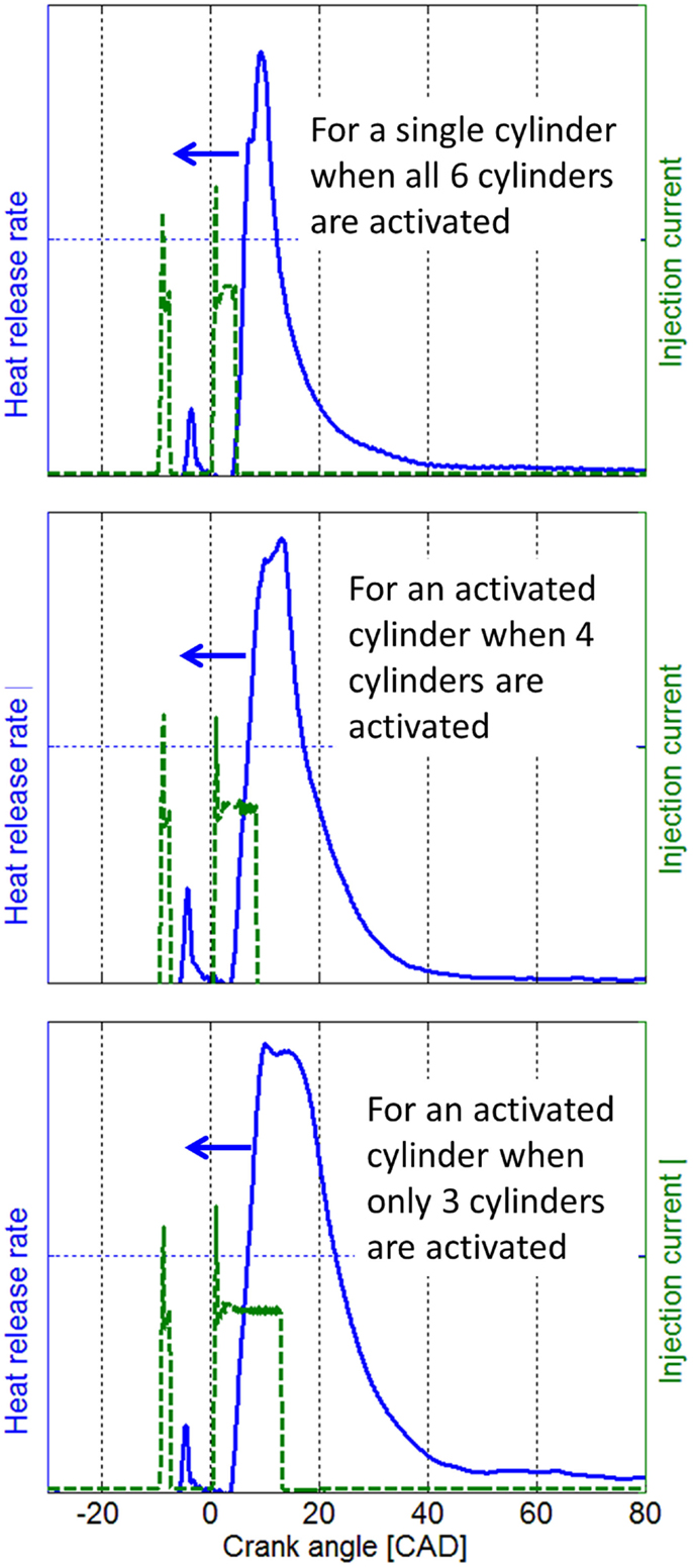
Figure 5. In-cylinder heat release and injector current comparison for most efficient six-cylinder, three deactivated cylinder, and two deactivated cylinder modes.
However, when the goal is to increase exhaust gas temperatures for exhaust thermal management (for instance, for active particulate filter regeneration) there are benefits to cylinder deactivation. Figure 3 demonstrates that turbine outlet temperatures in excess of 550°C are possible with cylinder deactivation, whereas the maximum possible temperature during six-cylinder operation does not exceed 420°C. The start of main injection (SOI) was delayed during both six-cylinder and cylinder-deactivated operation to realize increases in turbine outlet temperatures. Delaying SOI results in a delay of the in-cylinder heat release, decreasing closed cycle efficiency, and requiring more fuel to maintain load. The delayed heat release and higher fueling are consistent with higher turbine outlet temperatures, as shown in Figure 3. However, there are diminishing returns. As a specific example, delaying SOI during six-cylinder operation resulted in an increase in turbine outlet temperature from 350 to 420°C, but also an increase in the air flow, charge flow, and air-to-fuel ratio from more turbocharger boosting as a result of higher turbine inlet enthalpies. As shown, the air-to-fuel ratios increase for both conventional and cylinder-deactivated modes as SOI is delayed. Increases in air-to-fuel ratio are counterproductive with regard to increasing turbine outlet temperatures. In short, this is the reason why the turbine outlet temperatures for six-cylinder, two deactivated cylinder, and three deactivated cylinder modes top out at 420, 520, and 570°C, respectively. In fact, and as shown, there is little additional benefit of using delayed SOI in six-cylinder operation once the turbine outlet temperature has reached 400°C – as an additional 20°C temperature rise requires an additional 20% increase in fuel consumption.
Higher turbine outlet temperatures are realized with cylinder deactivation through a reduction in displaced volume. As fewer cylinders induct charge gas from the intake manifold a reduction in the air and charge flows is realized, driving an increase in turbine outlet temperature through reduced air-to-fuel ratios. Specifically, and as shown in Figure 3, the deactivation of two and three cylinders allows engine operation below air-to-fuel ratios of 20 and 17, respectively, resulting in significant (100–150°C) increases in turbine outlet temperature. Deactivating three cylinders clearly will result in lower air-to-fuel ratios than deactivating two cylinders. At this engine load, the deactivation of three cylinders results in an air-to-fuel ratio that is between 15 and 17, very close to the stoichiometric limit. As such, particulate matter generation at this operating condition is quite high – 2.9 FSN at 540°C, and 1.8 FSN at 570°C. This may not be a significant concern since active particulate filter generation would be occurring at the same time. However, a more conservative strategy would be to just deactivate two cylinders, during which time turbine outlet temperatures in excess of 520°C are still possible.
Obviously, the engine cannot directly heat the DPF to temperatures that are higher than the turbine outlet temperature. As such, there is a direct benefit of the higher temperature realized during cylinder deactivation, relative to six-cylinder operation. However, the heat transfer rate between the exhaust gas and the DPF does not only rely on turbine outlet temperature, but also the instantaneous exhaust flow rate and DPF temperature. As an approximation, consider the heat transfer rate between incoming gas and the DPF, as given in equation (2):
where is the mass flow rate of the exhaust gas going through the catalyst/tube, TDPF is the temperature of the DPF “wall,” and C is a constant that depends on the geometry and material of the DPF/tube.
Figure 6 shows the normalized exhaust gas-to-DPF heat transfer [calculated using equation (2)] as a function of DPF wall temperature for three cases with similar BSFCs: six-cylinder operation at a maximum temperature of 420°C, two deactivated cylinders at a maximum temperature of 520°C, and three deactivated cylinders at 540°C. In all cases, as the DPF temperature increases, the heat transfer rate between the incoming gas and DPF decreases as the (TOT − TDPF) term in equation (2) decreases. For conditions where the DPF wall temperature, TDPF, is higher than the turbine outlet temperature, TOT, the heat flow will be negative, and the gas flowing into the DPF will act to cool down the DPF. This scenario is shown in Figure 6 when the lines drop below the 0 line into the grayed area. As expected, the lines cross that threshold at a DPF temperature corresponding to the engine turbine outlet temperature. As illustrated, cylinder deactivation allows increases in the DPF temperature over 520°C (note that the 570°C case with three deactivated cylinders is not shown in Figure 6). Figure 6 also demonstrates that for all DPF temperatures above 0°C, the heat transfer rate is higher for the cylinder-deactivated cases. For instance, when the DPF temperature is 250°C, the two deactivated cylinder mode will result in a 75% increase in the heat transfer rate to the DPF (compared to six cylinder operation), shortening the time it will take for the DPF temperature to increase. The results are even more significant at a DPF temperature of 350°C, where the two deactivated cylinder mode will result in a 300% increase in the heat transfer rate. Additionally, the increased exhaust-to-DPF heat transfer, enabled via cylinder deactivation, yields a decrease in the fuel consumption relative to six-cylinder operation at the highest possible turbine outlet temperature. Specifically, the deactivation of two and three cylinders results in BSFC reductions of 2.1 and 3.3%, respectively, compared to the six-cylinder case.
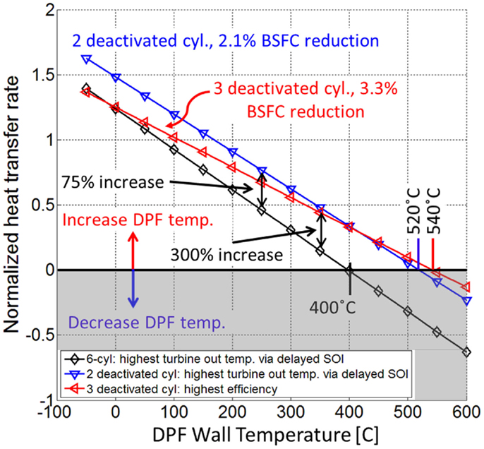
Figure 6. Normalized exhaust gas-to-DPF heat transfer rate comparison – higher fuel consumption modes.
Figure 7 shows a comparison of the normalized heat transfer rates for three additional cases corresponding to the lowest fuel consumption modes (as per Figure 3), including the highest efficiency, 350°C operation in six-cylinder mode, highest efficiency, 450°C operation in the two deactivated cylinder mode, and the 400°C operation in the six-cylinder model with slightly delayed SOI timing. Figure 7 shows that improved gas-to-DPF heat transfer will occur during the two cylinder-deactivated mode for DPF temperatures above approximately 220°C.
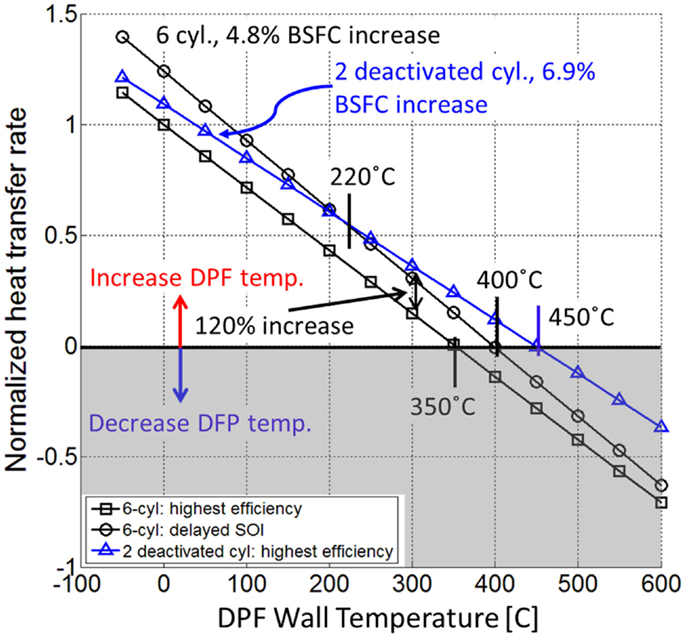
Figure 7. Normalized exhaust gas-to-DPF heat transfer rate comparison – lower fuel consumption modes.
Together, Figures 6 and 7 demonstrate that, compared to conventional six-cylinder operation, cylinder deactivation is a superior strategy for increasing DPF temperatures to levels required for active DPF regeneration.
5. Conclusion
The effort described above demonstrates that cylinder deactivation is an effective means of actively regenerating a diesel particulate filter without a fuel doser, diesel oxidation catalyst, or burner.
More specifically, the key observations at the 65 mile/h highway cruise condition – 1200 rpm/7.6 bar are:
Primary
1. The largest engine outlet temperature achievable during six-cylinder operation is 420°C, achieved with late SOI resulting in a 22% increase in fuel consumption (compared to the most efficient six-cylinder operating condition).
2. Deactivation of valve motions and fuel injection in two (of six) cylinders enables engine outlet temperatures of up to 520°C as a result of reduced air-to-fuel ratio.
3. Cylinder deactivation increases the rate at which the DPF will heat-up.
4. Per above, cylinder deactivation can be used to generate the 500–600°C diesel particulate filter-inlet temperatures required for particulate matter regeneration with oxygen without the need for a fuel doser, diesel oxidation catalyst, or burner.
Secondary
5. It is not possible to increase the efficiency (compared to the most efficient six-cylinder operating condition) of the engine through deactivation of valve motions and fuel injection in either two or three (of six) cylinders. Larger amounts of fuel must be injected into the activated cylinders to maintain the same load. Increases in injected fuel mass result in a larger injection interval causing spread out, delayed heat release, and higher in-cylinder heat transfer, both of which decrease the closed cycle and brake thermal efficiencies. The result is not surprising since the highway cruise condition is a critical design point for the engine during six-cylinder operation.
6. Deactivation of valve motions and fuel injection in three (of six) cylinders enables engine outlet temperatures of up to 570°C as a result of reduced air-to-fuel ratio. However, the PM is in excess of 1.8 FSN due to low air-to-fuel ratios. As such, deactivation of two cylinders (as per item 2 above) may be the preferred strategy for particulate filter regeneration.
6. Future Work
The development of control algorithms to smoothly move into, and out of, the CDA mode, as needed for DPF regeneration, is an additional effort that will be studied in the future.
Conflict of Interest Statement
The authors declare that the research was conducted in the absence of any commercial or financial relationships that could be construed as a potential conflict of interest.
Acknowledgments
Funding for this work was provided by Cummins Inc., and Eaton. Cummins also generously provided the experimental engine, technical support, and other experimental equipment.
References
Bach, E., Zikoridse, G., Sandig, R., Lemaire, J., Mustel, W., Naschke, W., et al. (1998). Combination of Different Regeneration Methods for Diesel Particulate Traps. SAE Technical Paper 980541. doi: 10.4271/980541
Bouchez, M., and Dementhon, J. (2000). Strategies for the Control of Particulate trap Regeneration. Technical Report, SAE Technical Paper 2000-01-0472. doi:10.4271/2000-01-0472
Breuer, J., Hirth, P., Brück, R., and Kruse, C. (1996). Electrically Heated Catalyst for Future USA and European Legislation. SAE Technical Paper 960339. doi:10.4271/960339
Ding, C., Roberts, L., Fain, D., Ramesh, A. K., Shaver, G. M., McCarthy, J., et al. (2015). Fuel efficient exhaust thermal management for compression ignition engines via cylinder deactivation and flexible valve actuation. Int. J. Eng. Res. doi:10.1177/1468087415597413
Edwards, K. D., Wagner, R. M., and Briggs, T. E. (2010). Investigating Potential Light-Duty Efficiency Improvements through Simulation of Turbo-Compounding and Waste-Heat Recovery Systems. Technical Report. Oak Ridge, TN: Oak Ridge National Laboratory (ORNL); National Transportation Research Center.
Foster, M. R., Foster, M. G., and Price, K. S. (2005). Engine Cylinder Deactivation to Improve the Performance of Exhaust Emission Control Systems. US Patent 6,904,752.
Gehrke, S., Kovács, D., Eilts, P., Rempel, A., and Eckert, P. (2013). Investigation of VVA-based exhaust management strategies by means of a HD single cylinder research engine and rapid prototyping systems. SAE Int. J. Commer. Veh. 6, 47–61. doi:10.4271/2013-01-0587
Heywood, J., and Welling, O. (2009). Trends in performance characteristics of modern automobile SI and diesel engines. SAE Int. J. Engines 2:1650–1662. doi:10.4271/2009-01-1892
Joshi, A., Chatterjee, S., Sawant, A., Akerlund, C., Andersson, S., Blomquist, M., et al. (2006). Development of an Actively Regenerating DPF System for Retrofit Applications. SAE Technical Paper 2006-01-3553. doi:10.4271/2006-01-3553
Magee, M. (2013). Exhaust Thermal Management Using Cylinder Deactivation. MSME thesis, Purdue University, West Lafayette, IN.
Mayer, A., Lutz, T., Lämmle, C., Wyser, M., and Legerer, F. (2003). Engine Intake Throttling for Active Regeneration of Diesel Particle Filters. SAE Technical Paper 2003-01-0381. doi:10.4271/2003-01-0381
Parks, J., Huff, S., Kass, M., and Storey, J. (2007). Characterization of In-Cylinder Techniques for Thermal Management of Diesel Aftertreatment. SAE Technical Paper 2007-01-3997. doi:10.4271/2007-01-3997
Singh, P., Thalagavara, A., Naber, J., Johnson, J., and Bagley, S. (2006). An Experimental Study of Active Regeneration of an Advanced Catalyzed Particulate Filter by Diesel Fuel Injection Upstream of an Oxidation Catalyst. SAE Technical Paper 2006-01-0879. doi:10.4271/2006-01-0879
Stanton, D. (2013). Systematic development of highly efficient and clean engines to meet future commercial vehicle greenhouse gas regulations. SAE Int. J. Engines 6:1395–1480. doi:10.4271/2013-01-2421
van Nieuwstadt, M., Upadhyay, D., Goebelbecker, M., and Ruona, W. (2003). Experiments in Active Diesel Particulate Filter Regeneration. SAE Technical Paper 2003-01-3360. doi:10.4271/2003-01-3360
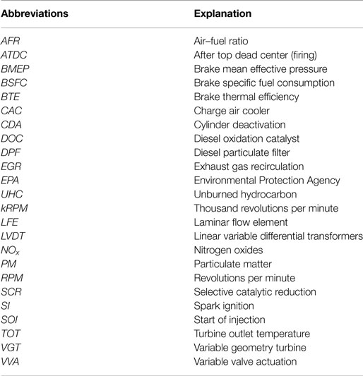
Appendix
Abbreviations
Keywords: thermal management, cylinder deactivation, VVA
Citation: Lu X, Ding C, Ramesh AK, Shaver GM, Holloway E, McCarthy J Jr., Ruth M, Koeberlein E and Nielsen D (2015) Impact of cylinder deactivation on active diesel particulate filter regeneration at highway cruise conditions. Front. Mech. Eng. 1:9. doi: 10.3389/fmech.2015.00009
Received: 25 June 2015; Accepted: 06 August 2015;
Published: 24 August 2015
Edited by:
Stephen Anthony Ciatti, Argonne National Laboratory, USAReviewed by:
Franco Concli, BMResearch, ItalyZhijiang Ye, University of California Merced, USA
Pete Schihl, U.S. Army Tank Automotive Research Development and Engineering Center, USA
Copyright: © 2015 Lu, Ding, Ramesh, Shaver, Holloway, McCarthy, Ruth, Koeberlein and Nielsen. This is an open-access article distributed under the terms of the Creative Commons Attribution License (CC BY). The use, distribution or reproduction in other forums is permitted, provided the original author(s) or licensor are credited and that the original publication in this journal is cited, in accordance with accepted academic practice. No use, distribution or reproduction is permitted which does not comply with these terms.
*Correspondence: Gregory M. Shaver, Ray W. Herrick Laboratories, Department of Mechanical Engineering, Purdue University, West Lafayette, IN 47907, USA, gshaver@purdue.edu