Review of Some Methods for Improving Transient Response in Automotive Diesel Engines through Various Turbocharging Configurations
 Evangelos G. Giakoumis
- Internal Combustion Engines Laboratory, School of Mechanical Engineering, National Technical University of Athens, Athens, Greece
Turbocharged diesel engines suffer from worse transient performance than their naturally aspirated counterparts, mostly at low loads and speeds. This leads to overshoot in engine-out exhaust emissions (primarily particulate matter/soot and NOx) after a speed or load increase, as well as poor drivability. The main cause for this problematic behavior is located in the turbocharger in the form of high moment of inertia and unfavorable aerodynamic-type compressor flow characteristics. In the present work, various alternative turbocharging configurations are reviewed that have proven successful in improving the dynamic diesel engine operation. These configurations are combined supercharging, variable-geometry turbine, electrically assisted turbocharging, two-stage series and sequential turbocharging, and lower turbine moment of inertia. Significant improvement in the engine’s transient response can be realized when designing for smaller turbocharger frames or applying more than one units (in series or parallel arrangement). Increasing the available turbine torque (e.g., through elevated turbine back pressure in a variable-geometry turbine) is another successful option, as well as enhancement of the boost pressure (e.g., through the use of a positive displacement compressor upstream of the turbocharger). Finally, the use of external energy (e.g., in the form of electrical assistance on the turbocharger shaft during the critical turbocharger-lag phase) is another recently developed and highly promising measure to mitigate the drawbacks of the poor transient performance of turbocharged diesel-engined vehicles and limit their exhaust emissions. The choice of the “best” configuration for a specific application depends on many parameters, such as cost, matching procedure, control system, and mainly type of engine and drive cycle of the vehicle.
Introduction
The diesel engine has assumed for many decades now a leading role in both the medium and medium-large transport sector. Major contributing factors have been its superior fuel efficiency over its spark ignition counterpart, coupled with high torque and increased reliability. By contrast, discrepancies in the form of exhaust smokiness, combustion noise radiation, and cold starting difficulty delayed its infiltration and broad acceptance in the highly competitive passenger car market. The extended use, however, of electronically controlled direct injection systems and sophisticated after-treatment control (most notably in the form of diesel particulate filters) has changed this trend in the recent years, with the majority of passenger cars sold in Europe being now compression-ignition engines (ACEA official website, 2016).
Among its many merits [e.g., absence of throttling, lean-mixture operation, high compression ratios (Heywood, 1988)], a very favorable feature of the diesel engine has been its inherent capability to operate supercharged. Supercharging increases the inlet air pressure and density usually applying a compressor located upstream of the engine. By so doing, the air-supply that enters the cylinders is increased accordingly, enabling efficient burning of proportionately higher amount of fuel. The obvious benefit here is the direct increase in the engine power; at the same time, down-sizing of the engine is possible (Zinner, 1978; Watson and Janota, 1982; Hiereth and Prenninger, 2007). Turbocharging – a special case of supercharging, where the expansion in a turbine of the exhaust gases leaving the cylinders supplies the power needed to drive the compressor – has been for many decades now the most preferred supercharging version for both compression and spark ignition engines. A distinctive advantage of a turbocharged engine is its capability to operate more efficiently compared to its naturally aspirated counterpart, hence, produces proportionately less CO2. Since concerns over greenhouse gas emissions are now reflected in the automotive engines legislation too (EU Directives 443/2009 EC for passenger cars and 510/2011/EC for light-duty vans), it is not surprising that the production of turbocharged (spark ignition and diesel engined) vehicles is constantly increasing. Nonetheless, turbocharging is characterized by a serious operating disadvantage in the form of problematic transient behavior. The term transient refers to engine speed or load changes, such as acceleration (continuously experienced by automotive engines), load increase (more common in industrial or marine engines), or even starting (Rakopoulos and Giakoumis, 2009).
During transients, it is the incoming air-supply that plays the most critical role for the engine response and not fueling. However, whereas breathing in a naturally aspirated engine is mainly determined by the engine speed, in a turbocharged engine it is strongly influenced by the operation of the turbocharger. The latter is responsible for an unfavorable engine behavior during transients through a well-established phenomenon known as turbocharger lag; turbo lag leads, on the one hand, to problematic torque build-up and poor vehicle drivability, and on the other, to a considerable increase in engine-out particulate matter (PM), gaseous, and even noise emissions (Watson and Janota, 1982; Winterbone, 1986; Rakopoulos et al., 2010a).
Obviously, the transient discrepancies are amplified when vehicular engines are involved since the biggest part of the daily driving schedule of passenger cars, buses, trucks, and non-road engines involves dynamic operation in the form of changing (engine) speed and fueling conditions. Probably, the most notable example is the PM peak evidenced as black smoke coming out of the exhausts of accelerating (older-technology) diesel-engined vehicles. It is not surprising, then, that the authorities in the European Union (EU), the US, Japan, and other countries have, for quite some time now, legislated driving (transient) cycle certification procedures for new vehicles and engines. This ensures that, to a large extent, the emissions during homologation are measured through a fairly realistic simulation of the vehicle’s/engine’s true daily transient pattern.
Since the core of the problems associated with the diesel engine’s transient response is located in the turbocharger, it is not surprising that many supercharging methods (mostly variations of the turbocharging concept) have been developed over the years to cope with the turbocharger lag and minimize the engine drivability problems and the overshoot in the emitted pollutants. The target of the present work is to review these methods with the focus on both performance and emissions; for the current survey, the two most prominent diesel engine pollutants are discussed, i.e., soot/smoke and nitrogen oxides. At the same time, the fundamentals and peculiarities of transient conditions will be highlighted and discussed. Since there are obvious difficulties involved in experimenting with different types of turbo or supercharging on the same engine (let alone during transients), most of the results to be presented in the next paragraphs derive from (experimentally validated) simulation codes (Rakopoulos and Giakoumis, 2006). The transient modes that will be surveyed in this review are primarily accelerations and, to a lesser degree, load increases. Hence, the focus will be on vehicular engine applications. Although “highly transient” in nature, cold and hot starting events will not be discussed in this article. This is partly not only due to article length issues but also because starting is characterized by some unique combustion and friction phenomena (Henein et al., 1992) that differentiate its operation from the usual speed or load-change transient pattern.
Fundamental Aspects of Diesel Engine Transient Operation
Despite its many advantages, turbocharging suffers from worse torque characteristics compared to natural aspiration, owing to the available exhaust gas energy not being sufficient enough at low loads and speeds to produce substantial boost. This behavior is subsequently reflected into problematic transient operation. It is considered helpful at this point to provide an initial background on the transient diesel engine response pattern. To this end, a typical discrete transient event will be discussed briefly in order to highlight the concept of turbocharger lag; a more in depth analysis of the subject is available in Rakopoulos and Giakoumis (2009).
Figure 1 illustrates an acceleration of a medium-duty turbocharged diesel engine commencing from a low engine speed and low load (i.e., first gear engaged in the gearbox). It demonstrates the response of four engine and turbocharger operating parameters as well as the development of the two most important diesel engine pollutants (smoke opacity1 and NO). Such a test, typical in the every-day operation of passenger vehicles and trucks, is quite demanding for both the engine and the turbocharger since the latter accelerates from practically zero boost. Consequently, it is a good example to pinpoint the peculiarities of transient response.
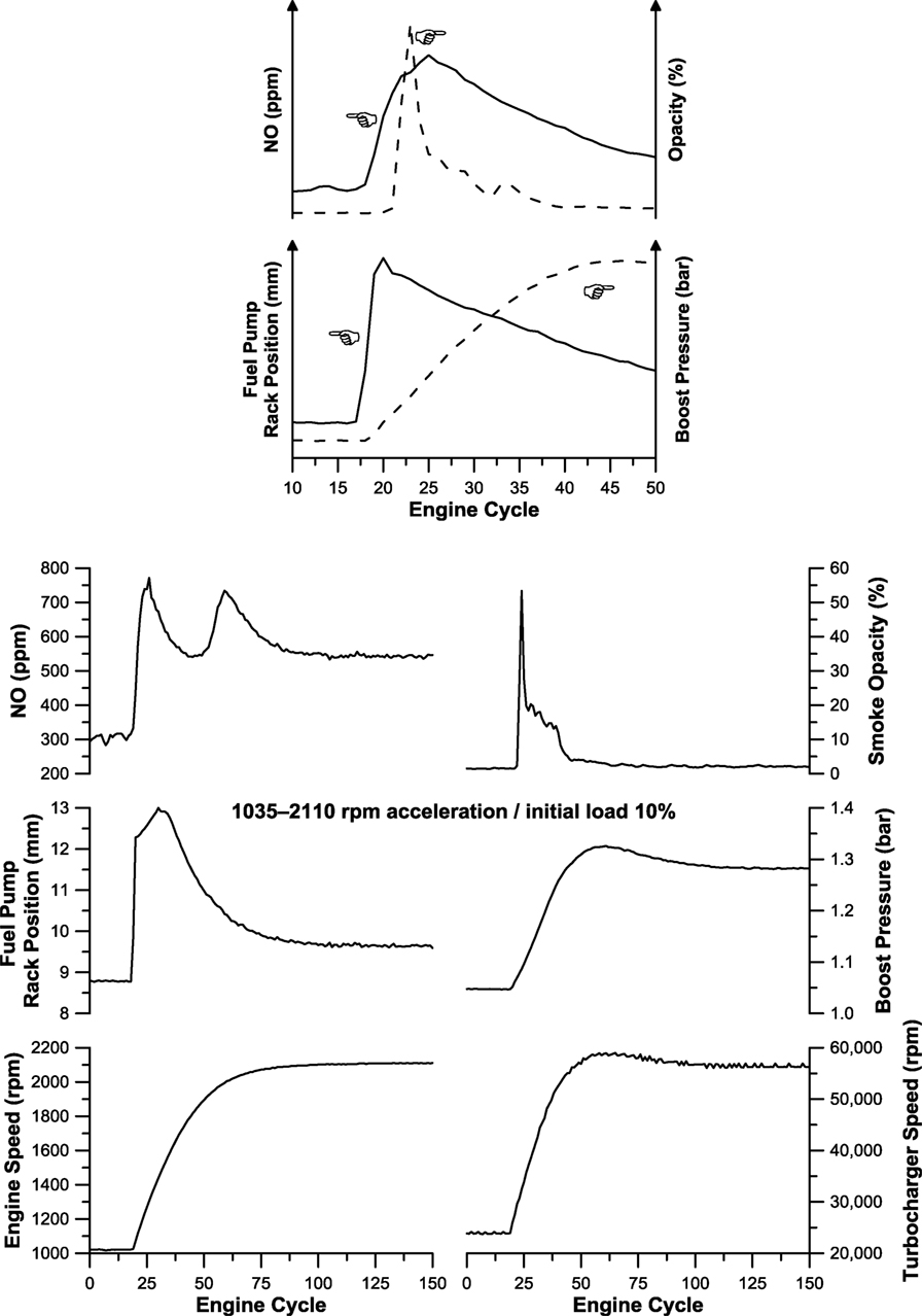
Figure 1. Upper diagram: comparison in the response between fueling and boost pressure (air-supply) highlighting the turbocharger lag and its inter-relation with smoke opacity and NO emission spikes (reprinted from Rakopoulos et al. (2010b) with permission from Elsevier); Lower diagram: development of engine and turbocharger properties, smoke opacity, and NO emission during typical turbocharged diesel engine acceleration (reprinted from Rakopoulos et al. (2010b) with permission from Elsevier).
As is made obvious from Figure 1, the fuel pump rack responds almost instantly to the fueling increase command and shifts to its maximum position, leading to higher fueling in a matter of a few engine cycles. In order for the engine to accommodate this elevated fueling, a proportionately higher amount of air is required. In a turbocharged engine, however, the amount of air inducted into the cylinders is determined by the compressor operating point and not by the engine speed alone. It is the unfavorable turbocharger compressor characteristics at low loads and speeds that lay the ground for problematic behavior here. Specifically, for an aerodynamic-type compressor, boost pressure depends strongly on rotational speed (see Figure 2). This means that in order to achieve the boost pressure and the inlet air-supply to match the increased fueling (hence, achieve the increased torque needed for the demanded speed change), acceleration of the compressor to a higher rotational speed is first required. Following Newton’s second law of motion for rotational systems, the equation that describes the turbocharger shaft angular momentum is
where MT and MC denote turbine and compressor torque, respectively, ωTC is the turbocharger speed, and ηmTC the shaft mechanical efficiency.
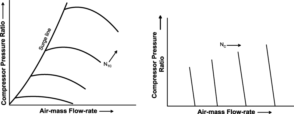
Figure 2. Comparison in the operating maps between typical aerodynamic-type (left) and positive displacement (right) compressors.
Unfortunately, the increased exhaust gas power produced by the engine is not capable of instantly raising the turbine torque MT. This happens primarily due to (a) the increased amount of heat transfer lost to the cylinder and exhaust manifold walls [the temperatures of which adapt to the new loading conditions slowly (Mavropoulos, 2011)]; (b) the subsequent filling of the exhaust manifold with the higher-enthalpy gas (hence, the use of pulse turbocharging systems in automotive engines with small-diameter and length exhaust pipes). Furthermore, and this is perhaps the most influential factor, the high turbocharger inertia GTC prohibits fast turbocharger shaft acceleration. Consequently, during the early cycles after a higher speed is demanded and increased fuel is injected, on the one hand, the higher temperature/enthalpy gas is not reflected into a proportionately higher turbine torque, and on the other, a large percentage of the turbine torque is lost in the acceleration of the shaft. Consequently, the compressor operating point moves rather slowly toward the direction of increased boost pressure and air-mass flow-rate. During this period (12 engine cycles or 1.17 s for the particular engine transient event in Figure 1), known as turbocharger lag, the engine is practically running in naturally aspirated mode or with very limited boost; the upper diagram of Figure 1 illustrates clearly the previous arguments by highlighting the delay between fueling and air-supply.
As a result of the slow turbocharger compressor reaction in Figure 1, the relative air–fuel ratio during the early cycles of acceleration assumes very low values (depending on the “harshness” of the transient event, even lower than stoichiometric). This is then reflected into a deterioration of combustion, which ultimately leads to slow engine torque and speed response and long recovery period. Predictably, the mismatch between fueling and air-supply has a direct impact on the soot emission profile too, provoking high opacity values and perhaps prolonged black smoke duration until the turbocharger has accelerated to a higher rotational speed, where the air-supply matches adequately the increased fueling.
Further to the air-supply deficiency, in-cylinder combustion issues amplify the problematic transient response pattern. At the beginning of the acceleration (or load increase), the initial higher-pressure fuel jets are injected into an air environment that is hardly unchanged from the previous steady-state conditions. This means that the higher-momentum fuel jet is not accompanied by equally enhanced gas motion. Thus, liquid fuel impingement on the cool combustion walls increases, lowering the rate of mixture preparation and enhancing its heterogeneity. Furthermore, the subsequent harder combustion course prolongs combustion and reduces the available time for soot oxidation.
In order to limit the increased soot emissions during transients, common ECU practice is
(a) to shift the fuel pump rack in relation to the achieved boost pressure, as is, for example, demonstrated in Figure 1. Initially, a rapid shift to a first peak position is observed, followed by a smoother movement to the maximum position. This behavior highlights the fuel limiter operating principle, which does not allow sharp fueling increases when the compressor boost pressure is still low. However (as will be discussed later in the text), this comes at a cost, namely the slower engine torque and speed response.
(b) to close the EGR valve, hence, fill the cylinders only with air and not recycled exhaust gas, this time at the expense of higher NOx emissions.
For the acceleration depicted in Figure 1, the mismatch between fueling and air-supply is quite prominent and lasts long too owing to the “hard” acceleration schedule (the demanded speed increase was approx. 1100 rpm). Fortunately, for accelerations from higher engine speeds or loads (i.e., with higher gear selected in the gearbox), the smoke overshoot is much lower. This is because the turbocharger accelerates now from an initial operating point of “sufficient” boost. The soot emission profile demonstrated in Figure 3 (soot emitted from the exhaust of a medium-duty turbocharged diesel-engined truck during continuous up-gear change schedule, e.g., when entering a highway) supports the latter argument. Likewise, during deceleration, no turbocharger lag and soot (or NOx) spike issues are experienced.
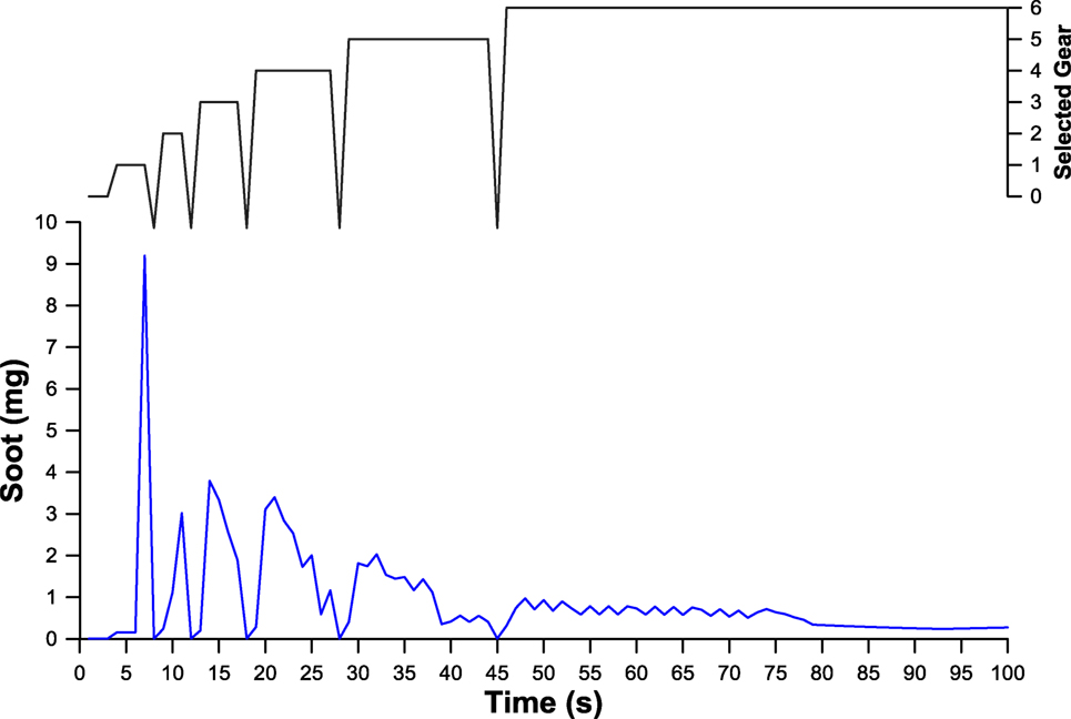
Figure 3. Soot emissions profile during continuous up-gear shift change of a 7.5 t turbocharged diesel-engined truck.
The lag between increased fueling and the response of the air-charging system discussed previously influences decisively (increases) the NOx concentration too as demonstrated in Figure 1 (Black et al., 2007; Giakoumis and Alafouzos, 2010). Since the main parameter affecting NO (and NOx) formation is the burned gas temperature, locally high temperatures due to close to stoichiometric air–fuel mixtures (formed because of the still low air-supply) are expected to increase NO during the turbocharger lag cycles in Figure 1. An additional factor that promotes NOx emissions during transients is the previously discussed typical ECU strategy to close the EGR valve when an acceleration event is sensed.
It has been argued in previous research (Watson and Janota, 1982; Winterbone, 1986; Rakopoulos and Giakoumis, 2009) that load increase transients (more typical in heavy-duty, non-road, and industrial engines) are even more difficult for the engine to cope with. Unlike acceleration, load increase initially causes drop in the engine speed, which constitutes another major burden for the engine to deal with, and, under circumstances, might even lead to stall if a very high loading is applied instantly.
In support to the arguments discussed in the previous paragraphs, Figure 4 illustrates the discrepancy between transient and quasi-steady operation during a typical transient event. From this Figure, the first important conclusion reached is that, contrary to the naturally aspirated engine’s linear torque response, the turbocharged (diesel) engine’s transient torque build-up is highly non-linear [the non-linearity enhances with engine rating/brake mean effective pressure (bmep)]. Moreover, during the early critical turbocharger lag engine cycles, the engine is clearly unable to achieve its quasi-steady performance (torque and power), leading to a torque deficit (sometimes considerable) that influences the whole transient event, and the emission of pollutants.
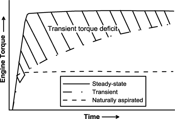
Figure 4. Comparison between transient and quasi-steady torque.
Summarizing that diesel engine transient response constitutes a highly non-linear phenomenon being influenced by a variety of engine and turbocharger parameters. The most important of these are (a) the dynamics of the system (most notably engine, vehicle, and turbocharger moment of inertia as well as manifolds’ volume), (b) the performance of the turbocharger (influential parameters here are the turbo-specific configuration/arrangement as well as the turbine nozzle area), and (c) various engine properties, such as the governor characteristics, the exact fueling pattern, the EGR strategy, and the valve timing. As argued in the previous paragraphs, the biggest contributor to the slow transient response is the turbocharger (characteristics/map and mass moment of inertia). There are, however, other important delays in the system that should be emphasized too; the most notable ones being
• the inertia of the reciprocating and rotating masses of the slider crank mechanism that prohibits fast response from a dynamic point of view,
• the increased amount of heat transfer to the cylinder and exhaust manifold walls due to the elevated fueling rate but still low wall temperatures,
• the filling of the exhaust manifold with the higher-enthalpy gas, and
• the filling of the inlet manifold with the higher density air.
Overview of the Methods for Improving Transient Response
In order to cope with the problematic transient behavior of a turbocharged diesel engine at low loads and speeds, there are two fundamental approaches:
(a) control of the fuel flow;
(b) speed-up of the in-cylinder, manifolds, and turbocharger response.
The former approach is usually realized through boost-pressure sensitive fuel limiters as described earlier. Fuel limiters control effectively the fuel flow to the engine in response to the inlet air-supply; hence, they succeed in reducing soot emissions. Specifically, fuel flow is limited until the boost pressure (hence, air-mass flow-rate) has assumed an adequate value so that very low values of air–fuel equivalence ratio (lambda) are prohibited. There is, however, a serious inherent drawback here, realized in the form of slower engine speed response, hence poorer (vehicle) drivability. Figure 5 highlights this trade-off through an extreme (non-realistic) but illustrative example, where the engine manages to avoid completely black smoke emissions throughout the transient event but at the same time, the time needed to achieve the demanded speed has increased disproportionately.
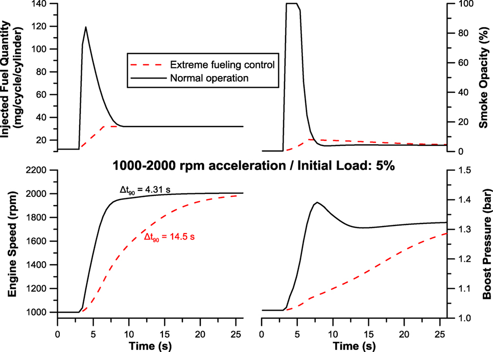
Figure 5. Comparison in the development of engine and turbocharger properties and smoke opacity between normal operation and an extreme fuel-control case [Δt90 corresponds to the time needed to reach 90% of final (demanded) speed] (simulation results from the GT-Power® software for a six-cylinder DI diesel engine).
It follows then that controlling only the fuel flow cannot be the sole measure during transients; instead, we have to investigate the core of the problem, which is located in the turbocharger (response). Nonetheless, some degree of fuel control is always employed.
Significantly better improvement can be realized through other methods that focus centrally on the transient response delays located in the turbocharger (or in the engine and manifolds for that matter). For example, and based on Eq. 1, decrease in the turbine moment of inertia or increase of the (turbine) torque can prove beneficial for a faster acceleration of the compressor, hence, increase of the air-supply to the engine cylinders.
The measures that will be reviewed in this article, all turbocharger-specific, are referenced below. They range from smaller-frame, low-inertia turbocharger units to sophisticated and expensive electronically controlled configurations, namely
• lower-inertia turbocharger;
• combined supercharging;
• two-stage turbocharging;
• variable-geometry turbine;
• sequential turbocharging; and
• electrically assisted turbocharging.
Schematic representation of all turbocharger configurations under consideration (together with their simplified control system) is provided in Figure 6.
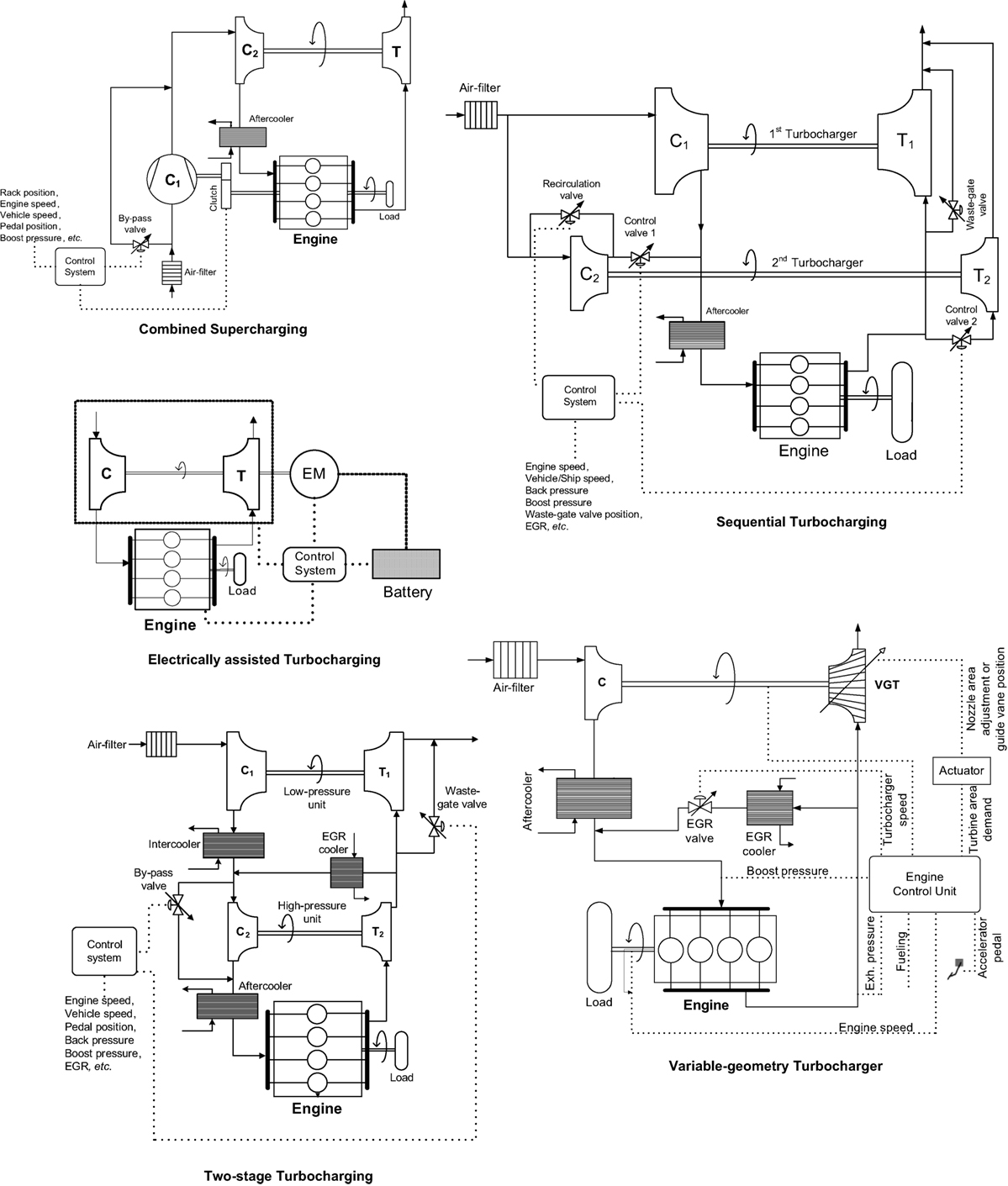
Figure 6. Schematic presentation of the turbocharger configurations used in the current analysis.
Turbocharger Mass Moment of Inertia
Perhaps the most obvious technique for faster turbocharger; hence, engine response is associated with the former’s mass moment of inertia. It has been estimated that at least 70% of the turbocharger’s inertia is typically associated with the turbine wheel, with the inertia of the turbocharger disk closely related to the fifth power of diameter (Watson, 1981). This suggests that reducing turbine (and compressor) rotor diameter will strongly influence turbocharger and, consequently, engine speed response. It is not surprising then that this method has been very popular among turbocharger manufacturers (and this irrespective of the specific supercharging configuration used). There are three fundamental ways to achieve a decrease in the turbo mass moment of inertia (Watson and Janota, 1982; Rakopoulos and Giakoumis, 2009).
The first one, which is the most straightforward, is by employing lighter materials, so as to decrease the turbine rotor mass (not size/nozzle area). Ceramic materials or silicon nitride are two successful choices here.
In V-type engine configurations, instead of using a single (i.e., bigger with larger diameter) turbocharger, two units can be installed, each one feeding a bank of cylinders. By so doing, the flow requirements for each unit are reduced to one half; at the same time, the gain in the inertia is much higher owing to the previously mentioned dependence of inertia on the fifth power of rotor diameter.
Lastly, the use of smaller-frame turbochargers can prove very effective. Smaller frame leads to (much) lower inertia, however, at the expense of lower turbocharger efficiency at the higher rotational speeds encountered. Luckily, as diameter is reduced, the penalty in efficiency changes much more slowly than inertia. When applying a smaller turbocharger frame, another adverse effect that arises is the fact that at high engine speeds and loads, over-boosting of the engine is experienced owing to the very high-pressure (HP) ratios induced at the elevated turbocharger speeds for the small turbine nozzle area. This may prove dangerous for safe engine (mechanical reasons) and turbocharger (over-speeding) operation. The usual counter-measure here is to install an exhaust waste-gate valve. The latter is usually internally built into the turbine casing, and consists of a spring-loaded valve, which gradually opens in response to the inlet manifold pressure allowing by-pass of a certain amount of exhaust gas directly to the atmosphere.
Based on Eq. 1, reducing the turbocharger inertia leads to faster acceleration of the turbocharger shaft, hence a higher turbo rotational speed is accomplished. Recall from Figure 2 that the higher is the compressor speed, the higher is its operating point in terms of both pressure ratio and air-supply to the engine cylinders. This means that greater amount of fuel can be injected into the engine and burned efficiently (fuel controller’s action is limited). The latter is then responsible for elevated engine torque as well as higher-enthalpy exhaust gas leaving the cylinder and feeding the turbine; this, in turn, produces more torque and drives the compressor to even higher operating points. As a result, the transient event develops faster and with smaller amounts of emitted soot.
The above arguments are highlighted in Figure 7 for a 1000–2000 rpm acceleration event of a turbocharged diesel engine initiating from a very low load. Notice that at the initial stage of the transient event (speed range from 1000 to 1200 rpm) where the boost pressure is minimal, the engine response is unaffected by turbocharger inertia. Here, it is practically the fuel controller that determines the torque and speed response of the engine. After a few tenths of a second, however, turbocharger acceleration is indeed affected by changes in inertia and this is then reflected into a faster engine speed response with limited fuel-controller action. For example, at the t = 7 s point in Figure 7, the lower-inertia turbocharger has already developed a pressure ratio of 1.3 compared with 1.15 for the higher-inertia one, allowing the fuel pump to inject more fuel. Ultimately, the duration of the acceleration for the lower-inertia turbocharger is almost 20% the time needed by its higher-inertia counterpart.
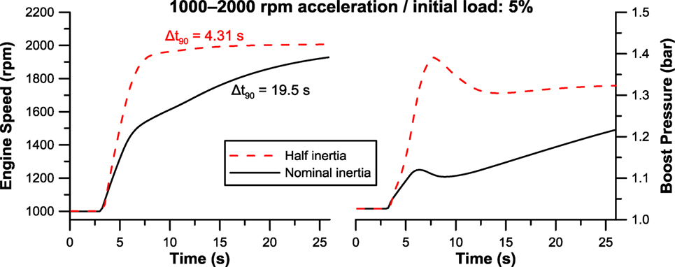
Figure 7. Effect of turbocharger mass moment of inertia on engine speed response (Δt90 corresponds to the time needed to reach 90% of final (demanded) speed).
Combined Supercharging
Mechanically assisted supercharging (i.e., positive displacement compressor coupled to the engine crankshaft) is characterized by two important attributes that favor smoother engine transient response. On the one hand, compressor speed is directly related to engine speed, meaning that every engine/vehicle acceleration is promptly “sensed” by the compressor. At the same time, the positive displacement compressors employed in such configurations (e.g., Roots or Lysholm) are capable of achieving high boost even at low rotational speeds owing to their flow characteristics, which are fundamentally different from those of their aerodynamic counterparts (see Figure 2 for a direct comparison between the maps of the two charging concepts). In any case, disadvantages in the form of higher fuel consumption (owing to the extra power needed to drive the compressor) and design issues (due to the mechanical connection between crankshaft and compressor) have limited the application of mechanical superchargers (Zinner, 1978; Hiereth and Prenninger, 2007).
The combined supercharging scheme (schematically demonstrated in Figure 6), on the other hand, is a fairly successful combination of the mechanically assisted supercharging and the exhaust gas turbocharging, benefiting from the advantages of both. It is realized through the use of a positive displacement compressor located upstream of the turbocharger compressor, and directly coupled to the engine crankshaft.
The main philosophy of the supercharging configuration is to support the turbocharger compressor at low engine loads and speeds, i.e., when the enthalpy capacity of the exhaust gases leaving the cylinders is still low; hence, the turbocharger compressor produces low boost. During this period, the positive displacement compressor is active, being capable of producing boost irrespective of its speed. The upper diagram of Figure 8 illustrates this behavior for a medium-duty turbocharged diesel engine coupled to a Lysholm-type compressor. It is obvious that the positive displacement compressor succeeds in significantly improving the low-load torque (bmep) curve of the engine. This is then reflected into limited fuel-controller action and (as will be discussed in the next paragraph) faster engine transient response. At the same time, however, the efficiency of the engine is reduced owing to the extra power needed to drive the compressor.
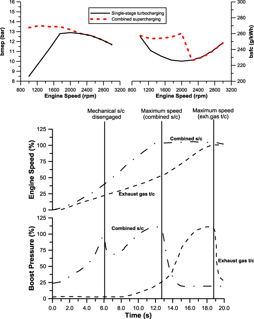
Figure 8. Upper diagram: comparison of steady-state bmep and bsfc between single-stage exhaust gas turbocharging and combined supercharging (simulation results from the GT-Power® software for a six-cylinder DI diesel engine); Lower diagram: improvement in engine transient response from a combined supercharging configuration (applying a Wankel-type positive displacement compressor) for a no-load 500–1900 rpm acceleration of a 40 t truck operating in tenth gear (data taken from Schmitz et al., 1994).
Application of a typical combined supercharging configuration on a vehicle yields the acceleration response demonstrated in the lower diagram of Figure 8. When using conventional exhaust gas turbocharging, the recovery period up to the demanded speed was 19 s; with combined supercharging, on the other hand, a remarkable 30% reduction was achieved. The main mechanism behind this noticeably faster acceleration is the fact that a sufficiently higher amount of engine torque was already available from the early cycles of the transient event, owing to the additional boost offered by the mechanical compressor. Moreover, since the positive displacement compressor is directly coupled to the engine, the increase of the engine speed is directly reflected into an increase of the compressor speed; hence, (according to Figure 2) the air-mass flow to the engine cylinders is enhanced too. On the contrary, the exhaust gas turbocharged engine was running for approximately 8 s with minimal boost (that is in a naturally aspirated mode), and only after 13 s did a significant increase in the engine speed rate occur.
Following the arguments made in the previous subsection, the fact that this configuration employs two compressors arranged in series provides further benefits. First, since the turbocharger is not the sole boosting device for the whole engine operating range, application of a smaller frame is enabled (with obvious benefits in terms of reduced inertia). At the same time, multiplication of the delivery pressure ratios from the two compressors is also established. As a result of the above, the action of the fuel controller is limited for the combined supercharging scheme, and the engine torque is built up faster and with predictably lower amount of emitted soot.
The main disadvantage of the combined supercharging configuration, namely the increase of the fuel consumption to cover the power losses to drive the positive displacement compressor, is highlighted in the upper diagram of Figure 8. It is made obvious that the positive displacement compressor is active only when the engine operates in the low–medium speed/load regime. At higher engine speeds, the delivery pressure provided by the turbocharger compressor is sufficient to boost the engine, and the positive displacement compressor is disengaged. During the transient event depicted in the lower diagram of Figure 8, the disengagement was realized at t = 6 s, which means that the positive displacement compressor was active for 50% of the time needed to achieve the demanded engine speed.
Two-Stage Turbocharging
The main purpose of two-stage turbocharging is to facilitate compression ratios above four bar, which cannot be achieved efficiently with single-stage units but is feasible with two units operating in series. Such compression ratios are then reflected into proportionately high engine ratings (typically above 23 bar bmep). Today, the most common applications of two-stage series turbocharging are to be found in large trucks as well as industrial/marine engines operating in the medium-speed range. In a typical two-stage series turbo configuration, the first unit is the low-pressure (LP) fitted upstream of the (usually smaller) HP one, with an aftercooler and, possibly, an intercooler between the two compressors (Choi et al., 2006; Winkler and Ångström, 2008; Lee et al., 2009). The efficiency advantage of turbocharging compared to naturally aspirated operation is amplified in the case of the two-stage configuration, as the elevated boost pressure offers the ability for even greater fuel savings (higher degree of down-sizing, better mechanical efficiency, operation of the two-stage units at regions with higher efficiency) (Galindo et al., 2010), whereas the increased air-supply accommodates higher EGR rates. Figure 9 supports the latter arguments by directly comparing some important properties [bmep, brake-specific fuel consumption (bsfc), lambda (indicative of soot emissions), and peak cylinder pressure] for a two-stage turbocharged engine vs. its single-stage and its naturally aspirated counterpart at steady-state conditions. In particular, the higher bmep of the two-stage unit, without penalty in lambda, is the most critical attribute, in the sense that higher fueling rates can be generally applied without fear of exhaust smokiness. At low engine speeds, however, the bmep curve remains unfavorable; hence, turbocharger lag effects are still present.
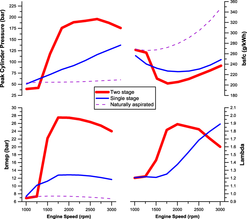
Figure 9. Comparison of bmep, peak cylinder pressure, bsfc, and lambda between single-stage, two-stage exhaust gas turbocharging and naturally aspirated engine operation (simulation results from the GT-Power® software for a six-cylinder DI diesel engine).
When considering the operation of two-stage units, two important issues need to be addressed. The first is the control system (see, for example, a simplified version in Figure 6) essential in automotive applications due to the highly changing operating conditions (e.g., “regulated” two-stage turbocharging). For example, the HP unit might be by-passed at high speeds and loads to avoid overboosting (Hiereth and Prenninger, 2007; Canova et al., 2009; Zhang et al., 2013). The second is the matching between engine and turbochargers, which is obviously a more difficult task compared to single-stage units, as the second turbocharger induces one more degree of complexity (Watel et al., 2010). In particular, the size ratio between the two units is of critical importance for both steady-state and transient operations.
Through the use of two-stage turbocharging, the engine benefits from better transient performance too primarily owing to the use of more than one units. The two units employed are obviously smaller in size, hence have much lower moment of inertia, whereas the multiplication of their delivery pressures, owing to the series arrangement, leads to even higher inlet air pressure. Moreover, since the HP unit operates at higher rotational speeds, it experiences smaller speed changes. Guzzella et al. (2000) argued that the higher degree of downsizing through two-stage turbocharging improves further the vehicle drivability by reducing overall vehicle weight too, as the smaller engine requires smaller and perhaps lighter engine subcomponents in the vehicle. As a result of the above arguments, the air-supply to the engine cylinders is higher when a two-stage configuration is employed, a fact that in turn leads to greater torque (limited fuel-controller action); at the same time, higher EGR rates can be accepted without fear of intolerable smoke emissions.
Indicative transient results, including emission data, are illustrated in Figure 10. This figure compares the response of a single and a two-stage unit for a medium-speed acceleration from 50% load. Clearly, the two-stage turbocharged engine was capable of both faster response and much smaller smoke opacity peak. This was due to the higher initial boost pressure, which enabled higher fueling rates from the onset of the acceleration.
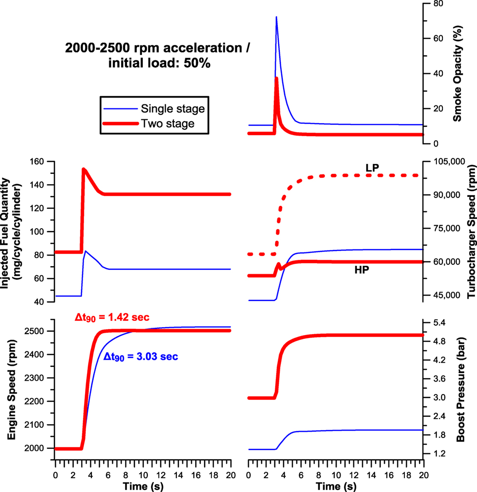
Figure 10. Two-stage vs. single-stage turbocharged diesel engine acceleration response from a medium load and for medium-to-high speed (simulation results from the GT-Power® software for a six-cylinder DI diesel engine).
In the same context, Choi et al. (2006) comparing two-stage series turbocharging with a variable-geometry turbocharger (VGT) found that the two-stage supercharging unit achieved faster transient response at 1000 and 2000 rpm and also higher torque at low engine speeds compared to the VGT. Following engine optimization, the bsfc was reduced for the same level of NOx, yielding comparable fuel economy for the two-stage unit as for the VGT.
Variable-Geometry Turbine
A very successful means for improving turbocharged diesel engine transient operation has been the use of variable-geometry turbines. Contrary to most of the other methods for improving transient response, however, the improvement here is not based on the reduction of the turbocharger inertia. Instead, the context behind this arrangement (see Figure 6 for a schematic presentation together with a simplified control system) is the adaptation of the turbine area to the continuously changing (engine) operating conditions. This adjustment is realized either through pivoting swing blade angles or by moving the nozzle sidewalls. In either case, the entire turbine map is changed, i.e., the system operates as a series of different turbine frames, each one “suited” to a specific engine operating region.
When the engine operates at the low speed/load region, the compressor boost pressure is typically low (the air-mass flow-rate to the engine too) owing to the low enthalpy potential of the exhaust gases leaving the cylinders. During this period, the turbocharger control system reduces the turbine area by closing down the vanes. By so doing, the pressure and temperature upstream of the turbine get higher. This is then reflected into higher turbine torque, thus, according to Eq. 1 acceleration of the turbo shaft to a higher rotational speed is established. The latter pushes the compressor operating point to higher-pressure ratios and mass flow-rates. The obvious benefit here is the fact that the smoke-limited (low-load/speed) operating range of a turbocharged diesel engine can be significantly reduced. The overall higher air-mass flow-rate and air–fuel ratio reduce smoke emissions, and, at the same time, the high exhaust gas pressure ensures that a positive pressure difference exists between the exhaust and inlet manifold, supporting the operation of the EGR and NOx control. When the engine speed and load are high enough, hence the boost pressure of sufficient magnitude, the nozzle area is increased by opening the blades. By so doing, excessive increase in boost pressure and turbo speed is prevented (Filipi et al., 2001; Gambarotta et al., 2011).
The previously discussed behavior of the VGT system is illustrated in Figure 11 regarding vehicle acceleration from low-load conditions. As soon as the transient event was sensed by the control system, the vanes were closed (turbine area reduced), a fact that aided the faster build-up of the boost pressure and turbocharger speed compared with the fixed geometry configuration. As a result, the time up to the intermediate speed of 2100 rpm was reduced by 15% for the VGT compared to the conventional vehicle. As soon as the boost pressure assumed an adequate value, the VGT vanes gradually opened to avoid over-boosting; this can be established in Figure 11 at the t = 3 s point, where a reduction in the delivery pressure is noticed.
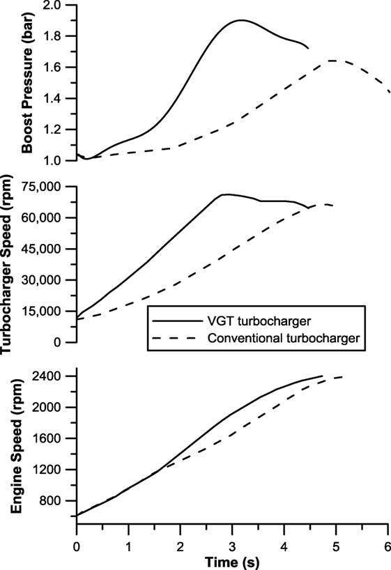
Figure 11. Effect of VGT on engine speed and turbocharger development during second gear acceleration from 600 rpm of a six-cylinder turbocharged diesel engine installed on a 20 t truck (figure adapted from Matsura et al., 1992).
The benefits from VGT are further illustrated in Figure 12, this time demonstrating smoke emission effects too. It is, in particular, the low-load, low-speed engine operating region that suffers more from turbocharger lag, slow response, and overshoot in soot emissions. As is clear from Figure 12, closing the vanes at low-load engine operation results in much “higher” turbocharger operating points that facilitate greater air-mass flow-rates; hence, the transient soot emissions are reduced considerably as regards both peak values and duration. Obviously, it is the specific VGT control strategy that determines the exact fueling profile in response to fast acceleration, and, at the same time, low emission overshoots.
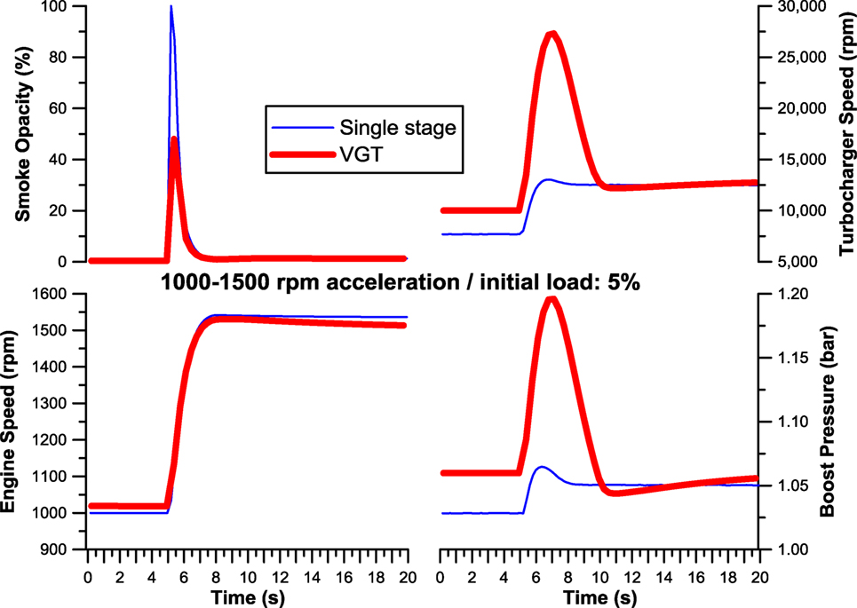
Figure 12. Comparison in the turbocharger and smoke emissions response between single-stage and variable geometry turbocharging of a medium-duty diesel engine during a low-load, low-speed acceleration (simulation results from the GT-Power® software for a six-cylinder DI diesel engine).
Obviously, a VGT system needs an extensive matching procedure so as to interact successfully with the engine, as well as a sophisticated control system that determines the exact opening/closing pattern with regard to various engine (including EGR control) and turbocharger parameters (Figure 6); cost is also an issue. The main drawbacks of the VGT system are located in the reduction of the engine and/or turbocharger efficiency. Predictably, the turbine cannot operate at optimum efficiency throughout the whole operating range (i.e., for all possible nozzle areas). Moreover, the increase in the back pressure at the low-load/speed conditions, necessitates higher pumping work by the engine to expel the exhaust gases from the cylinders, thus reducing the overall (in-cylinder) thermal efficiency.
Sequential Turbocharging
In contrast to the two-stage turbocharging discussed earlier, where two turbochargers operate in series, the sequential turbocharging configuration consists of two (or more) turbochargers connected in parallel. Common in both configurations is the fact that the use of smaller-size units aids faster response of the turbochargers and the engine. However, an important objective of the sequential arrangement is to widen appropriately the flow range for a specific boost pressure. Such turbocharging schemes (with up to four units) have been employed in marine engines, having demonstrated advantages in both the part load performance and transient response (Borila, 1986; Benvenuto and Campora, 2002; Hiereth and Prenninger, 2007; Zhang et al., 2013). Recently, sequential turbocharger configurations (with two units) have been applied to automotive engines too as the one depicted in Figure 6.
With reference to the schematic presentation in Figure 6, at part load, only the first turbocharger is active and the control valves are closed. During this period, control valve 2 and the recirculation valve are slightly open enabling operation of the second turbocharger at very low speed conditions so as to avoid thermal stress when this is suddenly engaged. The first turbocharger operates throughout the whole engine operating range; however, since it handles only part of the engine air-supply, it is smaller (smaller diameter), hence lighter, compared to a single-stage unit, with obvious advantages in terms of lower inertia and faster acceleration. The second unit operates in the medium-upper load range only, and may be even lighter. At high loads, control valves 1 and 2 open, and the second turbocharger engages fully. The engine now operates in a regulated “bi-turbo” configuration, adjusting the effective turbine total nozzle area (cf. VGT operation), while at the same time reducing the total moment of inertia of the active units compared to a single-stage configuration (Galindo et al., 2009).
It is obvious that the configuration is complex and requires a detailed and accurate matching process, particularly so to avoid the risk of surge when a unit is engaged or disengaged. The incorporation of aftercooler(s) and variable-geometry turbine(s) makes things even more complicated, as well as the use of more than two units (Ren et al., 1998; Zhang et al., 2013). Lastly, a comprehensive control algorithm is required that determines the exact point of the second (or third) unit’s (dis)engagement and handles appropriately all valves of the system.
Figure 13 illustrates transient operation results from a sequentially turbocharged automotive engine (Galindo et al., 2007), where the benefits from this configuration over a VGT engine are demonstrated. It is in particular the lower inertia of the sequential configuration compared to the VGT arrangement that is responsible for the better performance in Figure 13.
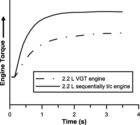
Figure 13. Comparison between VGT and sequentially turbocharged engine response during a load transient at 1500 rpm (figure adapted from Galindo et al., 2007).
As already mentioned, the major drawback of the parallel sequential arrangement is the high possibility of the compressor entering the unsteady region during the phasing in or out of the additional turbocharger unit(s). In order to cope with this serious problem, Galindo et al. (2009) investigated various control strategies. A corrective fuel control strategy achieved significant reductions in torque oscillations but resulted in low air–fuel ratio at full load. A “pre-lift” strategy involved slightly opening the valve responsible for controlling the second turbine during a transition in order to accelerate the corresponding compressor and increase the air downstream of the latter. This strategy, discussed earlier when describing the details of the sequential turbocharging configuration illustrated in Figure 6, effectively reduced the fluctuations by more than a factor of two. A third strategy applied a slow actuation to the valves controlling the turbochargers but proved less effective than the other approaches with respect to reducing oscillations under transient conditions.
An alternative sequential turbo approach was proposed by Zhang et al. (2008), who applied a three-phase approach; the first two phases correspond to operation of the smaller and larger turbochargers only, with the third phase consisting of both turbocharger units’ operation. The selection of each phase was based on the specific engine operating point. For example, only one of the turbochargers was employed to boost the engine at low-speed conditions, where the exhaust energy was low. This parallel turbocharger system displayed lower smoke emissions during transient operation and achieved better fuel efficiency than its single-stage turbocharger counterpart.
Electrically Assisted Turbocharging
According to Eq. 1, in order to accelerate the compressor and provide higher boost and air-mass flow to the engine, a proportionately high turbine torque is needed, which under low-load/speed conditions is not feasible. In order to address this problem, a possible solution is to provide extra power to the turbocharger shaft from an external source. Historically, the use of an external source to aid the transient response of a turbocharged diesel engine has been located in the compressor side, e.g., by providing compressed air (Winterbone, 1986). A more recent approach, this time on the turbine side, is the use of an electrically assisted turbocharging configuration; this makes use of an asynchronous (induction) electric motor (EM) or a synchronous type (e.g., reluctance motor or permanent magnet) mounted on the turbocharger shaft (Figure 6), also known as hybrid turbocharger (Shahed, 2006).
The EM can be (cost effectively) mounted within the turbocharger bearing housing. Alternatively, it can be installed outside the bearing housing, connected to the turbocharger rotor via a gearing system or, if positioned on the same axis of the turbocharger, via a coupling device. This results in a more difficult to package turbocharger, but the cooling of the EM is easier (Terdich et al., 2014). The power to drive the EM is usually drawn from the battery of the vehicle; predictably, this affects the efficiency and fuel consumption of the vehicle.
The primary application of such a configuration is in passenger cars and trucks offering additional power when an acceleration is detected; promising results have been reported, however, on marine engines too (Singh and Pedersen, 2016). Of great importance, here is the complex control system that takes into account many parameters of the engine, vehicle, and electrical system, and determines the exact timing of electrical power assist as well as its duration. Another parameter to be taken under consideration is the cost of the system. It should be also noted that incorporating an EM on the turbocharger shaft might require a re-assessed balancing of the shaft owing to the instability induced by the increased length and the introduction of electromagnetic forces. Cooling of the EM is also an important aspect of its development. Lastly, a higher capacity battery is most probably required for vehicular applications in order to assist the EM’s frequent function in the continuously changing driving conditions.
An alternative EM turbocharging configuration makes use of an EM driving a separate compressor (e-compressor or e-booster). The latter is installed upstream or downstream of its turbocharger counterpart in an arrangement that resembles the combined supercharging scheme discussed earlier (electrical supercharger + turbocharger). Further benefits from this arrangement are to be found in the multiplication of the pressure ratios of the two compressors, as well as the fact that the EM is not integrated in a high-temperature environment (Fieweger et al., 2002; Tavernier and Equoy, 2013; Newman et al., 2014).
In order to highlight the influence of the electrical assist (Figure 6) on the turbocharger shaft torque balance, Eq. 1 is re-arranged to also include the EM contribution
with MEM the EM torque and GTC+EM the combined turbocharger and EM mass moment of inertia. In order for the EM to offer advantage over the conventional turbo configuration, it follows that
Zellbeck et al. (1999) studied the effects of incorporating electrical assist on the vehicle performance during transients. Typical results are illustrated in Figure 14 for a full-load acceleration from 40 to 80 km/h in sixth gear. Upon onset of the acceleration, the EM supplied additional torque to the turbocharger shaft for a few seconds, accelerating it and increasing almost instantly the boost pressure and engine bmep. The reported benefit from the EM assist was up to 20% compared to the conventional waste-gated turbo operation. Similarly, encouraging results have been reported by Katrašnik et al. (2005a,b), who focused on load acceptance transients, as demonstrated in Figure 15. Obviously, the engine can benefit from the use of electrically assisted turbocharging even at steady-state conditions, with the EM assist facilitating operation at overall higher boost pressure levels. This is then reflected into a significant reduction of the fuel-limited low-speed region at the expense, however, of increased consumption as well as need for higher capacity battery (Balis et al., 2003). For the latter case, however, the use of an EMG system (G stands for generator) can prove beneficial.
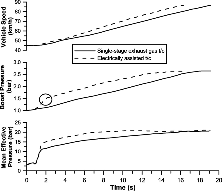
Figure 14. Acceleration performance of a diesel-engined vehicle with electrically assisted turbocharging (data taken from Zellbeck et al., 1999).
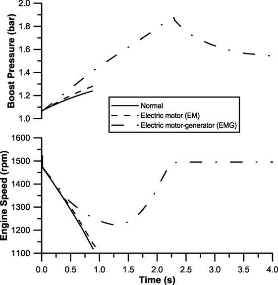
Figure 15. Effect of turbocharger electrical assistance on engine transient response after 0–97 kW load increase (data taken from Katrašnik et al., 2005a).
As already mentioned, manufacturers favor the use of smaller-frame turbochargers in order to reduce the inertia and, hence, turbocharger lag. Nonetheless, this results in over-boosting of the engine at high speeds, with a waste-gate valve serving in relieving the engine from the increased boost by rejecting part of the exhaust gas to the atmosphere. In an EMG configuration, on the other hand, work recovery can be established in the EM-generator when the available exhaust gas energy outweighs the engine needs (e.g., during highway driving). This work recovery can then be used to charge the batteries for future EM assist, or can be directed to other electrical appliances of the vehicle, or even in an electrical turbo-compound configuration (i.e., for mechanical power recovery), with obvious benefits in terms of reduced bsfc and CO2 emissions (Katsanos et al., 2013). Furthermore, the use of the generator serves also to assist the braking capacity of the vehicle.
Such an EMG turbocharging configuration has been described by Algrain (2005) with reported improvement in the overall (steady-state) fuel efficiency of the engine of the order of 5–10%. Engine drivability data for both acceleration and driving cycle performance were provided by Millo et al. (2006), who simulated the operation of a motor-generator electrically assisted turbocharging system (incorporating an asynchronous EM, DC–DC converter, super capacitors, and control system) for a heavy-duty diesel engine. The electrically assisted turbocharged vehicle was capable of reducing the time up to the desired boost pressure and turbocharger speed by 25% compared to the VGT engine for a typical acceleration event.
Conclusion
The transient operation of turbocharged diesel engines is particularly demanding in terms of engine response, engine sub-systems reliability, and exhaust emissions. It is a situation encountered continuously during the daily driving schedule of on-road and off-road vehicles, differentiating radically the engine operation from the respective steady-state conditions. It usually results in poor drivability and overshoot in the engine-out emitted pollutants (most notably particulate matter) particularly at low loads and speeds.
The core for the problematic transient response of turbocharged diesel engines is located in the response of the turbocharger, mainly due to its high moment of inertia, aided by the unfavorable aerodynamic-type compressor flow characteristics.
In the present work, five alternative turbocharging configurations were reviewed as regards their potential to improve vehicle drivability and limit the associated high emissions during transients. These were combined supercharging, two-stage series turbocharging, variable-geometry turbine, sequential turbocharging, and electrically assisted turbocharging as well as the use of lower-inertia turbocharger units.
From the discussion, it was revealed that perhaps the most important measure in order to limit the drawbacks of turbocharged diesel engine’s transient response is lowering the turbocharger’s mass moment of inertia. This can be realized by adopting lighter materials and/or multiple units connected in series or parallel.
Increase of the turbine’s torque through appropriately elevated turbine back pressure is another successful means, e.g., through the use of a variable-geometry turbine.
From the compressor side, on the other hand, enhancement of its boost pressure at low loads through the use of a positive displacement compressor located upstream of the turbocharger can provide significant improvement, however, at the expense of higher fuel consumption.
An alternative solution is to provide external assistance through the use of an electrical system acting either on the turbocharger shaft or as a supplemental electrical supercharger connected in series to the main turbocharging unit.
Dividing the engine air-mass flow-rate into more than one (smaller-size) units is another intriguing technique, e.g., through the use of a bi-turbo or better still sequential turbocharging configuration.
Most of the examined alternatives require sophisticated control systems and result in an increase of the engine weight/cost/complexity (sometimes fuel consumption too); however, their potential to improve transient engine performance seems rather clear. The choice of the “best” configuration for a specific application depends on many parameters, such as cost, matching procedure, control system, and mainly type of engine and drive cycle of the vehicle.
Author Contributions
The author confirms being the sole contributor of this work and approved it for publication.
Conflict of Interest Statement
The author declares that the research was conducted in the absence of any commercial or financial relationships that could be construed as a potential conflict of interest.
Abbreviations
bmep, brake mean effective pressure; bsfc, brake-specific fuel consumption; DC, direct current; DPF, diesel particulate filter; ECU, engine control unit; EGR, exhaust gas recirculation; EM, electric motor; EMG, electric motor-generator; NEDC, new European driving cycle; PM, particulate matter; VGT, variable-geometry turbine.
Footnote
- ^Although smoke opacity is not among the regulated emissions, it is often used by the researchers as a surrogate for the legislated particulate matter, which is difficult to measure instantaneously.
References
ACEA official website. (2016). Available at: http://www.acea.be/statistics/tag/category/diesel-penetration
Algrain, M. (2005). “Controlling an electric turbo-compound system for exhaust gas energy recovery in a diesel engine,” in IEEE International Conference on ‘Electro-Information Technology’. Lincoln, NE.
Balis, C., Middlemass, C., and Shahed, S. M. (2003). “Design and development of e-turbo for SUV and light truck applications,” in Diesel Engines Emissions Reduction Conference (DEER) (Newport, RI).
Benvenuto, G., and Campora, U. (2002). Dynamic simulation of a high-performance sequentially turbocharged marine diesel engine. Int. J. Engine Res. 3, 115–125. doi:10.1243/14680870260189244
Black, J., Eastwood, P. G., Tufail, K., Winstanley, T., Hardalupas, Y., and Taylor, A. M. (2007). Diesel Engine Transient Control and Emissions Response during a European Extra-Urban Drive Cycle (EUDC). SAE Technical Paper 2007-01-1938. Warrendale, PA: SAE International.
Borila, Y. G. (1986). A Sequential Turbocharging Method for Highly-Rated Truck Diesel Engines. SAE Technical Paper 860074. Warrendale, PA: SAE International.
Canova, M., Chiara, F., Rizzoni, G., and Wang, Y. Y. (2009). Design and Validation of a Control-Oriented Model of a Diesel Engine with Two-Stage Turbocharger. SAE Technical Paper 2009-24-0122. Warrendale, PA: SAE International.
Choi, C., Kwon, S., and Cho, S. (2006). Development of Fuel Consumption of Passenger Diesel Engine with 2-Stage Turbocharger. SAE Technical Paper 2006-01-0021. Warrendale, PA: SAE International.
Fieweger, K., Paffrath, H., and Schorn, N. (2002). “Drivability assessment of an HSDI diesel engine with electrically assisted boosting systems. Institution of mechanical engineers,” in 7th International Conference on ‘Turbochargers and Turbocharging’, Paper C602/009/2002 (London: IMechE), 283–293.
Filipi, Z., Wang, Y., and Assanis, D. (2001). Effect of Variable Geometry Turbine (VGT) on Diesel Engine and Vehicle System Transient Response. SAE Technical Paper 2001-01-1247. Warrendale, PA: SAE International.
Galindo, J., Climent, H., Guardiola, C., and Domenech, J. (2009). Strategies for improving the mode transition in a sequentially parallel turbocharged automotive diesel engine. Int. J. Automot. Technol. 10, 141–149. doi:10.1007/s12239-009-0017-1
Galindo, J., Luján, J. M., Climent, H., and Guardiola, C. (2007). Turbocharging System Design of a Sequentially Turbocharged Diesel Engine by Means of a Wave Action Model. SAE Technical Paper 2007-01-1564. Warrendale, PA: SAE International.
Galindo, J., Serrano, J., Climent, H., and Varnier, O. (2010). Impact of two-stage turbocharging architectures on pumping losses of automotive engines based on an analytical model. Energy Convers. Manag. 51, 1958–1969. doi:10.1016/j.enconman.2010.02.028
Gambarotta, A., Lucchetti, G., and Vaja, I. (2011). Real-time modelling of transient operation of turbocharged diesel engine. Proc. Inst. Mech. Eng. Part D J. Automob. Eng. 225, 1186–1203. doi:10.1177/0954407011408943
Giakoumis, E. G., and Alafouzos, A. I. (2010). Comparative study of turbocharged diesel engine emissions during three different transient cycles. Int. J. Energy Res 34, 1002–1015. doi:10.1002/er.1625
Guzzella, L., Wenger, U., and Martin, R. (2000). IC-Engine Downsizing and Pressure-Wave Supercharging for Fuel Economy. SAE Technical Paper 2000-01-1019. Warrendale, PA: SAE International.
Henein, N. A., Zahdeh, A. R., Yassine, M. K., and Bryzik, W. (1992). Diesel Engine Cold Starting: Combustion Instability. SAE Technical Paper 920005. Warrendale, PA: SAE International.
Hiereth, H., and Prenninger, P. (2007). Charging the Internal Combustion Engine. New York: Springer.
Katrašnik, T., Medica, V., and Trenc, F. (2005a). Analysis of the dynamic response improvement of a turbocharged diesel engine driven alternating current generating set. Energy Convers. Manag. 46, 2838–2855. doi:10.1016/j.enconman.2005.03.001
Katrašnik, T., Trenc, F., Medica, V., and Markič, S. (2005b). An analysis of turbocharged diesel engine dynamic response improvement by electric assisting systems. J. Eng. Gas Turbines Power 127, 918–926. doi:10.1115/1.1924533
Katsanos, C. O., Hountalas, D. T., and Zannis, T. C. (2013). Simulation of a heavy-duty diesel engine with electrical turbocompounding system using operating charts for turbocharger components and power turbine. Energy Convers. Manag. 76, 712–724. doi:10.1016/j.enconman.2013.08.022
Lee, B., Filipi, Z., Assanis, D., and Jung, D. (2009). Simulation-Based Assessment of Various Dual-Stage Boosting Systems in Terms of Performance and Fuel Economy Improvements. SAE Technical Paper 2009-01-1471. Warrendale, PA: SAE International.
Matsura, Y., Nakazawa, N., Kobayashi, Y., Ogita, H., and Kawatani, T. (1992). Effects of Various Methods for Improving Vehicle Startability and Transient Response of Turbocharged Diesel Trucks. SAE Technical Paper 920044. Warrendale, PA: SAE International.
Mavropoulos, G. C. (2011). Experimental study of the interactions between long and short-term unsteady heat transfer responses on the in-cylinder and exhaust manifold diesel engine surfaces. Appl. Energy 88, 867–881. doi:10.1016/j.apenergy.2010.09.018
Millo, F., Mallamo, F., Pautasso, E., and Mego, G. G. (2006). The Potential of Electric Exhaust Gas Turbocharging for HD Diesel Engines. SAE Technical Paper 2006-01-0437. Warrendale, PA: SAE International.
Newman, P., Luard, N., Jarvis, S., Richardson, S., Smith, T., Jackson, R., et al. (2014). “Electrical supercharging for future diesel powertrain applications,” in 11th Int. Conference on Turbochargers and Turbocharging (London: IMechE), 207–216.
Rakopoulos, C. D., Dimaratos, A. M., Giakoumis, E. G., and Peckham, M. S. (2010a). Experimental Assessment of Turbocharged Diesel Engine Transient Emissions during Acceleration, Load Change and Starting. SAE Technical Paper 2010-01-1287. Warrendale, PA: SAE International.
Rakopoulos, C. D., Dimaratos, A. M., Giakoumis, E. G., and Rakopoulos, D. C. (2010b). Investigating the emissions during acceleration of a turbocharged diesel engine operating with bio-diesel or n-butanol diesel fuel blends. Energy 35, 5173–5184. doi:10.1016/j.energy.2010.07.049
Rakopoulos, C. D., and Giakoumis, E. G. (2006). Review of Thermodynamic Diesel Engine Simulations under Transient Operating Conditions. SAE Technical Paper 2006-01-0884. Warrendale, PA: SAE International.
Rakopoulos, C. D., and Giakoumis, E. G. (2009). Diesel Engine Transient Operation. London: Springer.
Ren, Z., Cambell, T., and Yang, J. (1998). Investigation on a Computer-Controlled Sequential Turbocharging System for Medium Speed Diesel Engines. SAE Technical Paper 981480. Warrendale, PA: SAE International.
Schmitz, T., Holloh, K.-D., and Juergens, R. (1994). Potential of additional mechanical supercharging for commercial vehicle engines. MTZ 55, 308–313 (in German).
Shahed, S. (2006). An Analysis of Assisted Turbocharging with Light Hybrid Powertrain. SAE Technical Paper 2006-01-0019. Warrendale, PA: SAE International.
Singh, D. V., and Pedersen, E. (2016). A review of waste heat recovery technologies for maritime applications. Energy Convers. Manag. 111, 315–328. doi:10.1016/j.enconman.2015.12.073
Tavernier, S., and Equoy, S. (2013). Design and Characterization of an e-Booster Driven by an High Speed Brushless DC Motor. SAE Technical Paper 2013-01-1762. Warrendale, PA: SAE International.
Terdich, N., Martinez-Botas, R. F., Romagnoli, A., and Pesiridis, A. (2014). Mild hybridization via electrification of the air system: electrically assisted and variable geometry turbocharging impact on an off-road diesel engine. J. Eng. Gas Turbines Power 136, 031701. doi:10.1115/1.4025887
Watel, E., Pagot, A., Pacaud, P., and Schmitt, J. C. (2010). Matching and Evaluating Methods for Euro 6 and Efficient Two-Stage Turbocharging Diesel Engine. SAE Technical Paper 2010-01-1229. Warrendale, PA: SAE International.
Watson, N. (1981). Transient Performance Simulation and Analysis of Turbocharged Diesel Engines. SAE Technical Paper 810338. Warrendale, PA: SAE International.
Watson, N., and Janota, M. S. (1982). Turbocharging the Internal Combustion Engine. London: MacMillan.
Winkler, N., and Ångström, H.-K. (2008). Simulations and Measurements of a Two-Stage Turbocharged Heavy-Duty Diesel Engine Including EGR in Transient Operation. SAE Technical Paper 2008-01-0539. Warrendale, PA: SAE International.
Winterbone, D. E. (1986). “Transient performance,” in The Thermodynamics and Gas Dynamics of Internal Combustion Engines, Vol. II, eds J. H. Horlock and D. E. Winterbone (Oxford: Clarendon Press), 1148–1212.
Zellbeck, H., Friedrich, J., and Berger, C. (1999). Electrically assisted turbocharging as a new boosting concept. MTZ 60, 386–391 (in German).
Zhang, Q., Pennycott, A., and Brace, C. J. (2013). A review of parallel and series turbocharging for the diesel engine. Proc. Inst. Mech. Eng. Part D J. Automob. Eng. 227, 1723–1733. doi:10.1177/0954407013492108
Zhang, Z., Deng, K., Wang, Z., and Zhu, X. (2008). Experimental Study on the Three-Phase Sequential Turbocharging System with Two Unequal Size Turbochargers. SAE Technical Paper 2008-01-1698. Warrendale, PA: SAE International.
Keywords: diesel engine, transient operation, turbocharger, turbocharger lag, soot
Citation: Giakoumis EG (2016) Review of Some Methods for Improving Transient Response in Automotive Diesel Engines through Various Turbocharging Configurations. Front. Mech. Eng. 2:4. doi: 10.3389/fmech.2016.00004
Received: 01 February 2016; Accepted: 21 April 2016;
Published: 09 May 2016
Edited by:
Bengt Håkan Johansson, King Abdullah University of Science and Technology, Saudi ArabiaReviewed by:
Lu Qiu, Cummins Inc., USAJose Ramon Serrano, Universitat Politècnica de València, Spain
Copyright: © 2016 Giakoumis. This is an open-access article distributed under the terms of the Creative Commons Attribution License (CC BY). The use, distribution or reproduction in other forums is permitted, provided the original author(s) or licensor are credited and that the original publication in this journal is cited, in accordance with accepted academic practice. No use, distribution or reproduction is permitted which does not comply with these terms.
*Correspondence: Evangelos G. Giakoumis, vgiakms@central.ntua.gr