Laser Engineering Net Shaping of Microporous Ti6Al4V Filters
 Thomas Gualtieri
 Amit Bandyopadhyay
- W. M. Keck Biomedical Materials Lab, School of Mechanical and Materials Engineering, Washington State University, Pullman, WA, USA
In many applications, porous metal structures are necessary for proper and optimal function. Yet, these structures can be difficult to build. It is especially difficult if the pore size desired is very fine or on the microscale. For this reason, additive manufacturing processes have been looked at to build these structures. In this study, Laser Engineering Net Shaping (LENS™) processing was experimented with processing interconnected microporous structures. Using Ti6Al4V and only changing processing parameters, porous structures were created having porosity ranging from 21.5 to 15.4%. The microstructure proved to be that of traditional laser processed Ti6Al4V parts. Compression test of these samples showed that the ultimate compressive strength varied from 645 to 556 MPa. Overall, LENS™ proved to be a viable method to make unique interconnected microporous structures that could be easily added to any build without having to change the design.
Introduction
Porous metal structures serve an important function in several systems and are required for many applications. They have been used as filters, scaffolds, flame arrestors, and various other purposes that are difficult to replace with other materials. Interconnected microporous metal structures are especially difficult to make and only certain processes can produce such structures (Vamsi Krishna et al., 2008). In this study, the effects of Laser Engineering Net Shaping (LENS™) parameters on porosity and mechanical strength were investigated. The idea of manufacturability of interconnected microporous metal structures via LENS™ was tested, and the results were analyzed for interconnectivity as well as internal structure.
Additive manufacturing (AM) is starting to be adopted in many industries, including aerospace and medical (Bandyopadhyay et al., 2010; España et al., 2010; Bernard et al., 2012; Wauthle et al., 2015). AM has potential to make transformative changes in these fields by allowing design iterations in one process without any need for additional tooling (Buchbinder et al., 2011; Emmelmann et al., 2011). Such an approach can reduce the manufacturing cost as well as increase process efficiency (Bandyopadhyay et al., 2015a). In order for AM to make parts in one operation, it needs to be able to make all types of components, including porous and dense parts. Important factors must be taken into consideration when making microporous structures. Based on the application, features such as size, interconnectivity, shape, consistency, and surface area to volume ratio must be controlled. Porous metals in the past have been made to be used as filters, flow meters, pressure control, storage reservoirs, flame arrestors, attenuation devices, gas distribution, and media retention (Bandyopadhyay et al., 2015b). Many parts are housed internally in different systems, and it would be ideal to have these structures built internally, as opposed to adding it later during assembly. This is why AM is now being looked at to make these difficult structures, as well as new ones that could not be made before (Ryan et al., 2008).
LENS™ is a viable candidate for making controlled porosity structures. LENS works by depositing powdered metal under a continuous wave laser. The metal melts at the focal point of the laser, and then solidifies on the substrate that moves in the x and y directions. The head moves in the z, and the process can build a part layer-by-layer. In the past, many other processes have been used to make porous metal such as compressing and sintering titanium fibers, compressing and sintering particles, plasma spraying of powder, foaming by expansion of argon filled pores, and polymeric sponge replication (Li et al., 2006). LENS™ can be used to make porous structure by designing porosity as well as controlling process parameters. In the past, direct metal laser sintering (Khaing et al., 2001; Traini et al., 2008), direct laser forming (Hollander et al., 2006; Harrysson et al., 2008), select laser melting/select laser sintering (Vamsi Krishna et al., 2008; Yadroitsev et al., 2009), electron beam melting (Heinl et al., 2007; Parthasarathy et al., 2010; Cheng et al., 2012; de Peppo et al., 2012), multistage lost wax investment casting (Ryan et al., 2008), and 3D fiber depositing system (Li et al., 2006, 2007) have been used to make porous Ti6Al4V components. All these methods have their advantages and disadvantages when compared to each other. Direct metal laser sintering, direct laser forming, and electron beam melting all require a powder bed in order to build parts. Powder beds can help produce large overhangs, but powder must be removed after the part is finished. 3D fiber deposition uses a binder and dispersant to hold the metal suspension together before sintering, which is a post-processing step. These post-processing steps are setbacks when manufacturing and it would be ideal to avoid them. LENS™ unique capabilities of directly building a part and not requiring a powder bed or binder give it advantages over other AM processes. It also has the ability to modify the material and add secondary materials during the build, which may be needed when optimizing a system (Sahasrabudhe et al., 2015).
In this study, LENS™ parameters were adjusted to build parts with interconnected porosity with the lowest possible pore size. Of the smallest achieved pore size samples, interconnectivity, microstructure, and mechanical strength were analyzed.
Materials and Methods
LENS™ Processing of Porous Ti6Al4V Structures
Porous Filters were made using LENS™ 750 (Optomec Inc., Albuquerque, NM, USA). LENS™ operates by melting powder metal using a 500-W continuous wave Nd:YAG laser then depositing it on a substrate. Ti6Al4V powder (ATI Powder Metals, Pittsburgh, PA, USA) that was −100/+325 mesh was deposited under the laser from a hopper via argon transport. It is delivered under the laser through four nozzles that are positioned around the beam. It is then melted and deposited on the substrate where it solidifies. The platform then moves in the x and y directions, and the deposition head moves in the z direction. It builds a part layer-by-layer while the laser powder, powder feed rate, scan speed, hatch angle, and hatch distance are controlled to achieve desired structure and part properties. This is all done in an argon atmosphere with oxygen levels held below 10 ppm. Samples were made to have a 12-mm diameter and were 10 mm in height, though height varied based on build quality. An image of the LENS™ process can be seen in Figure 1. All samples were built using only Ti6Al4V powder on a Ti6Al4V plate.
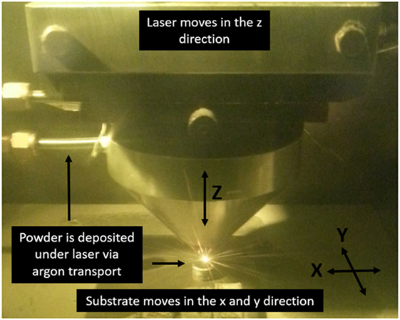
Figure 1. Laser engineered net shaping (LENS™) – a freeform powder-based additive manufacturing process.
Designing Parameters for Porous Structure
Processing parameters were first chosen based on past work done on LENS™ (Balla et al., 2007; Xue et al., 2007). Other AM methods have previously used designed porous structure made in a CAD file to build scaffolds (Bose et al., 1999; Hollander et al., 2006; Ryan et al., 2008; Cheng et al., 2012; de Peppo et al., 2012). This was considered before building the samples for this study. Due to past knowledge of how the LENS™ runs, it was decided to try and control porosity by only changing the build parameters. By doing this, it would mean the user would not have to make a designed porosity in the CAD file, but only have to change build parameters in a certain location to make a porous structure with known properties. Testing was done by first researching how porous structures were built in the past. Each sample had either the powder feed rate, scan speed, hatch distance, angle of hatch layer, or slice distance adjusted based on the previous builds results. Due to so many parameters and a large range of values for each, not all combinations could be tested. Fist a base parameter was chosen that in the past had shown to make a porous structure. From there hatch distances were adjusted by increments of 0.125 mm, and each sample was made with a [0/90]° and [0/120/240]°configuration. After analysis, powder feed rate parameters were adjusted based on results. With the last build, the slice height was adjusted depending on if laser went out of focus during build. After determining the parts with the lowest porosity, five samples were made using these parameters to test reproducibility and compression strength.
SEM Analysis of Pores and Microstructure
The microstructure and apparent pore size was observed using a field emission scanning electron microscope (FEI Quanta 200) (FEI Inc., OR, USA). The samples were all first ground and polished until they had a mirror surface. This was done starting with 200 grit SiC and successively using higher grits, ending at 1200. Polishing was done using 1, 0.3, and 0.05 μm alumina suspensions on a velvet cloth wheel. First, the samples were looked at under the SEM, so pore size could be estimated visually. The samples were then removed and etched using Kroll’s Reagent (2 ml hydrofluoric acid, 6 ml nitric acid, and 92 ml DI water). Etched samples were then viewed in SEM to observe the microstructure.
Pore Shape and Interconnectivity Test
Proof of pore interconnectivity was done by physical testing as well as running micro CT scans. The physical testing was done by observing if air would pass though the samples. An apparatus was made that clamped the sample cylinders down and did not let air pass around the sides. This can be seen in Figure 2. One side had an opening where an air compressor hose was attached. The other side was open to the environment. The apparatus was immersed in a water tank where a camera was set up in front of it. Air was then let in on the one side of the sample from an air compressor. If bubbles released from the sample, it proved there was interconnectivity. Next, the apparent porosity of the samples was calculated using the Archimedes method by measuring the dry and the wet weight in water (Darsell et al., 2003). From this, the density of the sample was calculated to compare with the density of standard Ti6Al4V to show accuracy of pore calculation.
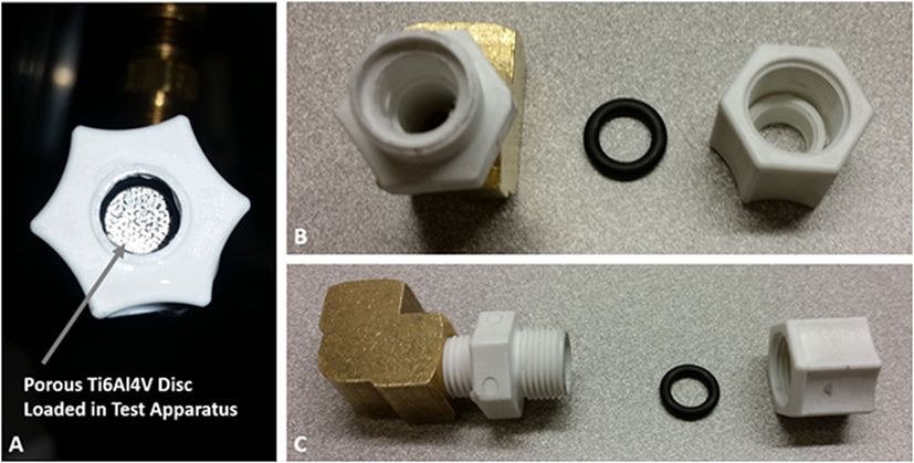
Figure 2. Image of interconnected porosity test apparatus. (A) Apparatus loaded with a porous Ti6Al4V disc before testing. (B) Front view of test apparatus. (C) Side view of test apparatus.
Compressive Strength Test
Compression tests were conducted on samples built using the parameters that produced the lowest porosity. Three cylinders were built to be 7 mm by 14 mm to try and achieve 2:1 diameter to height ratio. Tests were conducted on a screw-driven universal testing machine (AG-IS, Shimadzu, Japan). A stroke rate of 0.5 mm/min was used. The samples were pressed until they fractured. The stress–strain response was then plotted and ultimate compressive strength (UCS) was determined.
Results
Parameters and Properties
When building the scaffolds, it was found that best way to build the porous structures was by using a low laser power and slow scan speed. Parameters and porosity calculations can be seen in Table 1. The parameters listed are from the final build and samples that exhibited the lowest porosity. Sample 2 resulted in the lowest calculated porosity and images of it can be seen in Figures 3–5. Porosity calculations of sample 2 can be seen in Table 1. It was found that it had a porosity of 15.4% with pore interconnectivity. It is important to note that there is some inherent variability in powder-based AM processes, such as LENS™. The starting powder size can vary between 50 and 150 μm. Keeping the laser power and other process parameters the same, such powder size variation alone, can create variations in final porosity. Based on our experience, a ±2% porosity variation in porous structures via LENS™ is quite common even after extensive process optimization.
Table 1. Processing parameters for Ti6Al4V structure.a
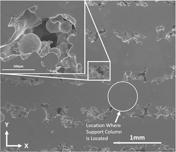
Figure 3. LENS™ processed Ti6Al4V porous structure, sample 2 from Table 1. The z direction, which is the build direction, is normal to the image.
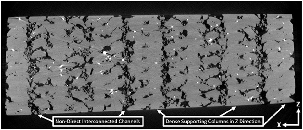
Figure 4. LENS™ processed Ti6Al4V μCT image of internal porous structure.
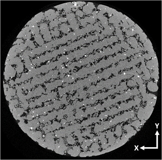
Figure 5. LENS™ processed Ti6Al4V μCT image of top surface of porous structure.
The average porosity of the final samples was 17.4% with the highest porosity sample being 21.5%. It should be noted that earlier builds produced samples with much larger apparent porosity that are not listed in the table. Using the weight measurements used to calculate the porosity, the density of the metal was calculated. It came out to be 4.40 ± 0.03 g/cm3 which is what past research has also found Ti6Al4V to be (Yusop et al., 2012). This verifies the calculations accuracy and that most all pores are open. If there was closed porosity the buoyancy of the internal channels would cause the density calculation to have variation (Matyas et al., 2011).
Pore Shape, Size, and Morphology
Figure 3 shows the image of the polished top section of sample 2 from the table. It can be seen that there are pore openings in linear patterns going across the sample in the x direction. Within the larger pores, there are spherical-shaped structures randomly oriented. These can also be seen in Figure 5. These structures are partially sintered Ti6Al4V. One advantage of free form laser-based AM processes is there is no stress being applied to the build, such as in molding processes. No mechanical force being applied to powder-based parts has been known to lead to porosity (Kruth et al., 2007). The metal is in powder form when deposited under the laser. The low laser powder does not fully melt the powder as fast as higher powers. Then as a hatch is being built, a melt pool forms and grows. It grows larger the longer the laser is at that location. By having a slow scan speed, the melt pool has time to grow and fully melt in the center. At a certain width, the powder is being deposited on top of the hatch, slightly above the focal point of the laser, as well as on the sides of the hatch. Due to it not being directly under the laser, and the laser power being relatively low, the powder only partially sinters on the sides. This leaves the spherical structure seen in between the larger pores in Figure 3.
The larger pores are in a linear pattern due to the formation between the hatches. Each dense area is where a scan of the laser was making a hatch. The pore shape looks random across each pore. The pores in between the hatches are not continuous and are broken in intervals. This is due to the [0/90]° build orientation. This makes the pores form into a pattern, but each pore has a random shape, and filled partially with sintered powder. It should also be noted that the areas between pores appear to have no porosity and are fully dense.
This pattern can also be seen in Figure 4 which is a micro-CT scan of the cross-section of sample 2. There were column-like structures that appeared to be fully dense in the direction of the build. In between them were layers in the horizontal direction that were fully dense. Within the open areas between them, there were small spots of material in spherical shapes. The columns were where the hatches crossed when being built in the [0/90]° configuration. The layered areas were spots that only the hatch going in either the 0° or 90° direction was heading. In between the hatches were the partially sintered Ti6Al4V. It also appears that the outside is almost fully dense, but may have some voids allowing for gas transfer.
Microstructure
Microstructural images can be seen in Figure 6 of Ti6Al4V porous structures. The grain structure consists of homogeneous acicular grains that are quasi-directional in certain areas. This is due to epitaxial growth of grains, while the part is being built layer-by-layer (Cain et al., 2014). The needle-like grains are acicular α′ (HCP) grains (Hosford, 2010). This is typical of LENS™ processed Ti6Al4V due to fast cooling rates. The areas where the acicular grains are oriented in the same direction are where β (BCC) grains existed (Bose et al., 1999). When the metal first begins to solidify, it forms the β phase, which then begins to transform to the α phase upon further cooling (Cain et al., 2014). The fast cooling does not allow for a full transition to the α phase due to no time for the V atoms to diffuse out of the β structure (Bandyopadhyay et al., 2009). This results in a martensitic type structure with fine α′ plates (Cain et al., 2014). Then as the alloy cooled rapidly the acicular α grains developed. Some areas such as in Figure 6 are quasi-directional martensitic type acicular grains.
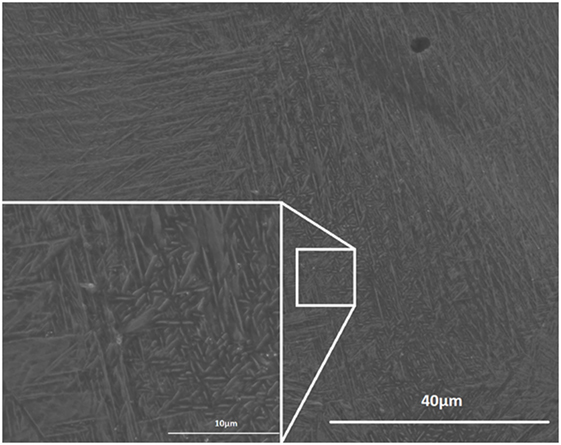
Figure 6. Image of LENS™ processed Ti6Al4V microstructure, 2500× and 10000× magnification.
Compression Testing
When building the samples for testing, the parameters for sample 2 from Table 1 were used because it produced the lowest porosity. Ideally, this would produce samples with the exact same porosities. This did not prove to be the case and it was found that there was some variability in the measured porosities. Out of the five cylinders built using the same parameters, the porosity ranged from 15.8 to 21.9%, with an average porosity of 19.3% and SD of 2.0%. Table 2 shows the different porosities of the samples built for compression testing. The samples were all built using a STL file of a cylinder that was 7 mm diameter and 14 mm tall. Due to the large hatches and contours of the build, the cylinder’s dimensions on average were 9.5 mm diameter and 15.9 mm tall. Therefore, the ratio of height to diameter on average was 1.7, slightly less than 2:1.
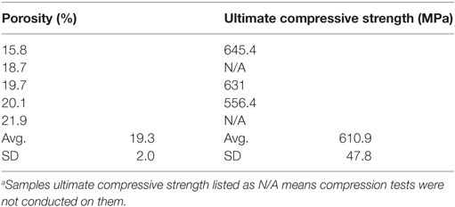
Table 2. Porous Ti6Al4V compression test.a
Figure 7 shows the stress–strain plot from the compression tests. Only three tests were done in order to preserve two of the samples. They all follow a similar trend of starting linear, then as the pores start to collapse, the slope gradually decreases. This continues until the UCS is reached, and the porous structure catastrophically fractures 45° to the axial direction. This is common for metals because they fail in shear, which is 45° to the axial directions (Hibbeler, 2011). Figure 8 shows images of the 19.3% sample before and after testing. It also shows an image of the samples after compressive testing. It can be seen that the 15.8 and 19.3% samples both fractured in the 45° direction. Figure 9 is an image of the fracture surfaces of the 15.8% porous sample. There were clear signs of shearing and plastic deformation that resulted in a planar fracture 45° to the axial direction. Globules of the partially sintered powder can be seen distributed across the fracture surface. Surrounding them are planar surfaces that were the supporting structure that have plastically deformed and failed in the 45° direction.
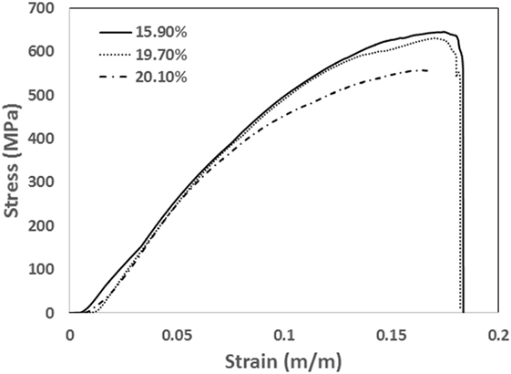
Figure 7. Stress–strain plot of compression test of porous Ti6Al4V cylinders. Although processed using the same parameters, different porosities were measured for each sample. The respective porosities of each compression test are listed on the plot.
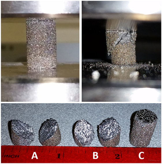
Figure 8. Top left: 19.7% sample loaded for compression test. Top right: 19.7% porous structure fractured at 45°. Bottom: samples after compression test: (A) 15.9%, (B) 19.7%, and (C) 20.1%.
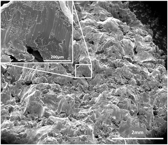
Figure 9. Fracture surface of 15.8% porous sample. Cylinder axial direction is normal to the image.
The 15.8 and 19.7% samples have curves that continue all the way until no load is present. The 20.1% curve, however, stops as the slope becomes negative. This was due to the machine reading that the sample had fractured and it stopped recording data. It is believed that the 20.1% sample would follow the same trend as the last two though and would fracture shortly after UCS. The UCS is listed for the three samples in Table 2. As is expected, the UCS increases with decreasing porosity.
Discussion
Microstructure
The laser processed microstructure of Ti6Al4V has been known to change the properties of the metal. The martensitic-like structure tends to increase the hardness due to the alloying elements forming tiny compounds, such as Ti3Al. These small compounds are hard spots that improve microhardness. This can also make the structure more brittle. The dispersed α′ grains that are randomly oriented in a martensitic type manner are characteristic of Widmanstatten structure (Collins et al., 2003). This happens when α laths group together, which happens during the β to α transition. To truly know the mechanical properties and hardness of these structures, more mechanical testing must be done.
Building Porous Ti6Al4V Structures
Finding the proper hatch distance, powder feed rate, build angles, and laser power proved to be difficult. In order to make a very small pore size, there needed to be very little distance between each hatch. As laser power increased, more material melted, and resulted in thicker hatches. Likewise, as the powder feed rate was increased, larger hatches were made. If a larger hatch was made the hatch distance needed to be adjusted to achieve the desired spacing. Other factors such as the angle of each layer were deposited changed pore size as well. Figure 10 is an image of the different build orientations. It can be seen that as more orientations are used, the smaller the pore sizes became. Depending on hatch size, one angle pattern could have interconnected porosity and one may be fully dense. This was just another parameter than needed to be taken into consideration when building the filters.
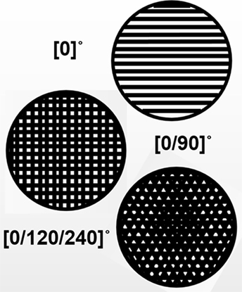
Figure 10. Images of build orientations showing how it changes pore size.
It was found that a hatch distance of 0.625 and 0.75 mm worked well to make small gaps between hatches, when the PFR was 17.9 g/min and laser power was 373W. To make fully dense Ti6Al4, generally a laser power of 40 W is used. A low laser power was used in order to only partially sinter the Ti6Al4V powder and make a structure of powder metal all partially bonded together. This would make very fine channels between areas that were left open by the hatches. Therefore, the structures had larger channels for air flow; however, randomly oriented, partially melted powders in these channels also obstruct direct flow.
Morphology of Structure
The resulting scaffold structure provides many advantages over traditional manufacturing and other AM processes. The partially sintered powders obstruct passage ways that are present throughout the scaffold. In Figure 4, these globules of Ti6Al4V can be seen in the middle of the channels. This increases the filtering ability of the structure as well as the surface area. Porous structures have been used in the past as catalyst for various processes. For higher efficiency, it is optimal to have the highest surface area per unit volume (Yadroitsev et al., 2009). The small globules in the LENS™ processes structure provide an increase in surface area, as well as extra filtration ability if used for such an application.
These obstructed channels are unique to LENS™ processed samples compared to other AM processes. Other AM processes can make porous structures with interconnected porosity, as listed in the Section “Introduction.” Many of them can make fine interconnected porosity and channels as well. A distinct difference the LENS™ process has is the randomness and internal obstruction of the interconnected channels. Figure 11 shows schematic representing different types of internal porosity. Some AM processes can make microporous scaffolds, but only have internal channels that run strait through the sample. This means that the only thing obstructing flow or filters undesirables is the channel size. This type of pore can be seen in Figure 11A. Many of the other AM processes used to make scaffolds also can make designed porosity with internal channel structures that make a non-direct path through the sample. It is a large advantage of other AM systems that they have the ability to make designed porosity then make a scaffold almost exactly as the design (Bose et al., 1999; Yadroitsev et al., 2009). The channels then obstruct direct flow, increasing filtering capability and surface area of the structure. Figure 11B is an example of this type of structure. As mentioned before, the porous structures in this study were not made from a CAD-designed pore structure, but by adjusting the processing parameters of the build. The pore structure was created by producing hatches near each other, then having powder spill over and partially sinter between them. This left a scaffold with the structure of Figure 11A, but added random oriented powder in between the hatches. The partially sintered particles build up and obstruct the passages in the center of the channel as well as add extra surface area and roughness. A representative schematic of this can be seen in Figure 11C. This structure could be favored in applications where high surface area and filtration capabilities are required.
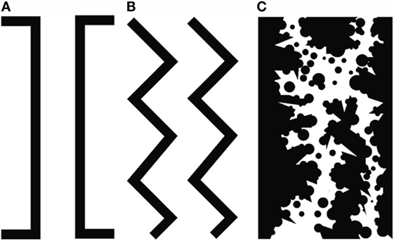
Figure 11. Images of different pore structure AM is capable of making. (A) Direct channel where gas and particles that are smaller than the pore size can pass through. (B) Non-direct channel where gas and items cannot directly pass, but structure is still open between channels. (C) LENS™ processed porous structure with non-direct channels, variability on walls, and obstructions in between passage ways.
Another advantage to the LENS™ processed structure is the dense supporting columns that are present across the samples. Figure 4 shows the columns present in the z direction of the build. These columns form where two hatches cross each other during the build. Figure 4 in particular is an image of a [0/90]° specimen. This means the columns form where the 0° crosses the 90° hatch. Figure 3 point out where this would be located on the top section. These structures add strength and structural integrity to the scaffold. They are oriented in the x, y, and z directions, giving support in the horizontal and vertical directions. The number and direction of these support columns can be changed with different hatch orientation. For example, samples 3 and 4 were built using [0/120/240]°. This would mean there were support structures in all these directions, as well as the z direction.
As expected, the UCS decreased with increasing porosity. Something that occurred was there was a much larger difference in the UCS between the 19.7 and 20.1% porosity (74.6 MPa) compared to the difference between 15.8 and 19.7% (14.5 MPa). This could possibly suggest as porosity continues to increase, the UCS begins to decrease at an increasing rate. Yet, there is not enough data to draw any major conclusions. In one study, the compressive strength of 17% porous pure titanium structure developed using LENS™ processing was found to have an UCS of 463 MPa (Xue et al., 2007). This was the closest study found to the testing done for this paper. The 17% porous titanium had 182.4 MPa less than the 15.8% sample from this study. There were no other reports of UCS of Ti6Al4V with this low of porosity to compare the results to. The UCS of pure Ti6Al4V is ~1000 MPa (Hibbeler, 2011). This means that the addition of 15.8% porosity reduces the UCS by roughly 35%. Overall, this shows the scaffold still had a relatively high UCS even with the added porosity, and is still substantially more than CP-Ti with roughly the same porosity.
Designed vs. Processed Porosity
When comparing the designed porosity and the LENS™ processed porous structures, there are pros and cons for each. The designed porosity can yield very predictable structures with homogeneity. It can be tailored to have different sizes and integrated into a design of a larger structure. Yet, it would be difficult or impossible to create a designed porosity that has the morphology of the LENS™ processed structure. As mentioned earlier, this structure could be favorable for high surface area and filtration applications. One problem that always arises with random structure is if it is reproducible. In our study, we found that using the same parameters yielded near the same porosity (±2.0%), build quality, and always produced interconnected porosity. It can be seen in Figure 4 that even though there is variation across the structure, the overall structure has the same pattern. From this, it can be said that the structure is reproducible and consistent with a small degree of error.
Another large advantage is these structures can be added to a part at any given time during the build. Since this porosity was not designed in a CAD file, it can manually be added to any structure by simply changing the building parameters. This could add simplicity to a build instead of trying to add porosity to the CAD model of the entire part. Although this tactic may not be ideal for all situations, it could prove to be an easy solution in some. We plan to continue this work to understand the influence of porosity toward mechanical properties of LENS™ processed parts.
Summary
Porous structures are an important and needed structure in many modern day applications. They are difficult structure to make, especially if fine interconnected porosity is desired. AM processes have been looked at to make these structures due to their versatility and ability to make intricate geometries. In this study, LENS™ was used to make microporous structures out of Ti6Al4V. The structure was made by changing the build parameters as opposed to designing a CAD model of the pore structure. After optimization of build parameters, interconnected porous structures were made with porosity ranging from 21 to 15.4%. The structures had a supporting network of dense columns with obstructed interconnected channels in between them. The obstructions were made by partially sintered Ti6Al4V powder using a slow scan speed and low laser power. Visual analysis of the structure shows it would have higher surface area and be ideal for use as a filter due to the globules of metal in the center of the interconnected channels. The structure had an UCS that varied from 645 to 556 MPa. The microstructure was similar to that of laser processed Ti6Al4V with martensitic-like grains. Overall, LENS™ proved to be a viable way to make porous structure by only changing build parameters, which means the structure could be added to any part of a build and implemented easily on designs.
Author Contributions
All authors listed have made substantial, direct, and intellectual contribution to the work and approved it for publication.
Conflict of Interest Statement
The authors declare that the research was conducted in the absence of any commercial or financial relationships that could be construed as a potential conflict of interest.
Funding
Authors like to acknowledge financial support from the Joint Center for Aerospace Technology Innovation (JCATI) and the National Science Foundation under the grant number CMMI 1538851. TG also likes to acknowledge support from Hydro Research Foundation for providing him 1 year graduate research fellowship.
References
Balla, V. K., Bose, S., and Bandyopadhyay, A. (2007). Low stiffness porous Ti structures for load-bearing implants. Acta Biomater. 3, 997–1006. doi:10.1016/j.actbio.2007.03.008
Bandyopadhyay, A., Espana, F., Balla, V. K., Bose, S., Ohgami, Y., and Davies, N. M. (2010). Influence of porosity on mechanical properties and in vivo response of Ti6Al4V implants. Acta Biomater. 6, 1640–1648. doi:10.1016/j.actbio.2009.11.011
Bandyopadhyay, A., Gualtieri, T., and Bose, S. (2015a). “Global engineering and additive manufacturing,” in Additive Manufacturing, eds A. Bandyopadhyay and S. Bose (Boca Raton, FL: CRC Press), 1.
Bandyopadhyay, A., Bose, S., Bandyopadhyay, A., and Bose, S. (2015b). “Additive manufacturing: future of manufacturing in a flat world,” in Additive Manufacturing (Boca Raton, FL: CRC Press), 367.
Bandyopadhyay, A., Krishna, B. V., Xue, W., and Bose, S. (2009). Application of laser engineered net shaping (LENS™) to manufacture porous and functionally graded structures for load bearing implants. J. Mater. Sci. Mater. Med. 20(Suppl. 1), S29–S34. doi:10.1007/s10856-008-3478-2
Bernard, S., Vamsi Krishna, B., Bose, S., and Bandyopadhyay, A. (2012). Compression fatigue behavior of laser processed porous NiTi alloy. J. Mech. Behav. Biomed. Mater. 13, 62–68. doi:10.1016/j.jmbbm.2012.04.010
Bose, S., Sugiura, S., and Bandyopadhyay, A. (1999). Processing of controlled porosity ceramic structures via fused deposition process. Scr. Mater. 41, 1009–1014. doi:10.1016/S1359-6462(99)00250-X
Buchbinder, D., Schleifenbaum, H., Heidrich, S., Meiners, W., and Bültmann, J. (2011). High power selective laser melting (HP SLM) of aluminum parts. Phys. Procedia 12(part 1), 271–278. doi:10.1016/j.phpro.2011.03.035
Cain, V., Thijs, L., Van Humbeeck, J., Van Hooreweder, B., and Knutsen, R. (2014). Crack propagation and fracture toughness of Ti6Al4V alloy produced by selective laser melting. Addit. Manuf. 5, 68–76. doi:10.1016/j.addma.2014.12.006
Cheng, X. Y., Li, S. J., Murr, L. E., Zhang, Z. B., Hao, Y. L., Yang, R., et al. (2012). Compression deformation behavior of Ti-6Al-4V alloy with cellular structures fabricated by electron beam melting. J. Mech. Behav. Biomed. Mater. 16, 153–162. doi:10.1016/j.jmbbm.2012.10.005
Collins, P. C., Banerjee, R., Banerjee, S., and Fraser, H. L. (2003). Laser deposition of compositionally graded titanium-vanadium and titanium-molybdenum alloys. Mater. Sci. Eng. A 352, 118–128. doi:10.1016/S0921-5093(02)00909-7
Darsell, J., Bose, S., Hosick, H., and Bandyopadhyay, A. (2003). From CT scans to ceramic bone grafts. J. Am. Ceram. Soc. 86, 1076–1080. doi:10.1111/j.1151-2916.2003.tb03427.x
de Peppo, G. M., Palmquist, A., Borchardt, P., Lennerås, M., Hyllner, J., Snis, A., et al. (2012). Free-form-fabricated commercially pure Ti and Ti6Al4V porous scaffolds support the growth of human embryonic stem cell-derived mesodermal progenitors. ScientificWorldJournal 2012, 1–14. doi:10.1100/2012/646417
Emmelmann, C., Sander, P., Kranz, J., and Wycisk, E. (2011). Laser additive manufacturing and bionics: redefining lightweight design. Phys. Procedia 12(part 1), 364–368. doi:10.1016/j.phpro.2011.03.046
España, F. A., Vamsi Krishna, B., Bose, S., and Bandyopadhyay, A. (2010). Design and fabrication of CoCrMo alloy based novel structures for load bearing implants using laser engineered net shaping. Mater. Sci. Eng. C 30, 50–57. doi:10.1016/j.msec.2009.08.006
Harrysson, O. L. A., Cansizoglu, O., Marcellin-Little, D. J., Cormier, D. R., and West, H. A. (2008). Direct metal fabrication of titanium implants with tailored materials and mechanical properties using electron beam melting technology. Mater. Sci. Eng. C 28, 366–373. doi:10.1016/j.msec.2007.04.022
Heinl, P., Rottmair, A., Körner, C., and Singer, R. F. (2007). Cellular titanium by selective electron beam melting. Adv. Eng. Mater. 9, 360–364. doi:10.1002/adem.200700025
Hibbeler, R. C. (2011). Mechanics of Materials, 8th Edn. Upper Saddle River, NJ: Pearson Prentice Hall.
Hollander, D. A., Von Walter, M., Wirtz, T., Sellei, R., Schmidt-Rohlfing, B., Paar, O., et al. (2006). Structural, mechanical and in vitro characterization of individually structured Ti6Al4V produced by direct laser forming. Biomaterials 27, 955–963. doi:10.1016/j.biomaterials.2005.07.041
Khaing, M. W., Fuh, J. Y. H., and Lu, L. (2001). Direct metal laser sintering for rapid tooling: processing and characterisation of EOS parts. J. Mater. Process. Technol. 113, 269–272. doi:10.1016/S0924-0136(01)00584-2
Kruth, J. P., Levy, G., Klocke, F., and Childs, T. H. C. (2007). Consolidation phenomena in laser and powder-bed based layered manufacturing. CIRP Ann. Manuf. Technol. 56, 730–759. doi:10.1016/j.cirp.2007.10.004
Li, J. P., De Wijn, J. R., Van Blitterswijk, C. A., and De Groot, K. (2006). Porous Ti6Al4V scaffold directly fabricating by rapid prototyping: preparation and in vitro experiment. Biomaterials 27, 1223–1235. doi:10.1016/j.biomaterials.2005.08.033
Li, J. P., Habibovic, P., van den Doel, M., Wilson, C. E., de Wijn, J. R., van Blitterswijk, C. A., et al. (2007). Bone ingrowth in porous titanium implants produced by 3D fiber deposition. Biomaterials 28, 2810–2820. doi:10.1016/j.biomaterials.2007.02.020
Matyas, J., Wegeng, R. S., Robinson, M. J., Casella, A. M., and McCloy, J. S. (2011). “Experimental characterization of thermal wadis in support of lunar exploration,” in AIAA Space 2011, Paper AIAA 2011–7364, American Institute of Aeronautics and Astronautics, Reston, VA.
Parthasarathy, J., Starly, B., Raman, S., and Christensen, A. (2010). Mechanical evaluation of porous titanium (Ti6Al4V) structures with electron beam melting (EBM). J. Mech. Behav. Biomed. Mater. 3, 249–259. doi:10.1016/j.jmbbm.2009.10.006
Ryan, G. E., Pandit, A. S., and Apatsidis, D. P. (2008). Porous titanium scaffolds fabricated using a rapid prototyping and powder metallurgy technique. Biomaterials 29, 3625–3635. doi:10.1016/j.biomaterials.2008.05.032
Sahasrabudhe, H., Harrison, R., Carpenter, C., and Bandyopadhyay, A. (2015). Stainless steel to titanium bimetallic structure using LENS™. Addit. Manuf. 5, 1–8. doi:10.1016/j.addma.2014.10.002
Traini, T., Mangano, C., Sammons, R. L., Mangano, F., Macchi, A., and Piattelli, A. (2008). Direct laser metal sintering as a new approach to fabrication of an isoelastic functionally graded material for manufacture of porous titanium dental implants. Dent. Mater. 24, 1525–1533. doi:10.1016/j.dental.2008.03.029
Vamsi Krishna, B., Xue, W., Bose, S., and Bandyopadhyay, A. (2008). Engineered porous metals for implants. JOM 60, 45–49. doi:10.1007/s11837-008-0059-2
Wauthle, R., Vrancken, B., Beynaerts, B., Jorissen, K., Schrooten, J., Kruth, J.-P., et al. (2015). Effects of build orientation and heat treatment on the microstructure and mechanical properties of selective laser melted Ti6Al4V lattice structures. Addit. Manuf. 5, 77–84. doi:10.1016/j.addma.2014.12.008
Xue, W., Krishna, B. V., Bandyopadhyay, A., and Bose, S. (2007). Processing and biocompatibility evaluation of laser processed porous titanium. Acta Biomater. 3, 1007–1018. doi:10.1016/j.actbio.2007.05.009
Yadroitsev, I., Shishkovsky, I., Bertrand, P., and Smurov, I. (2009). Manufacturing of fine-structured 3D porous filter elements by selective laser melting. Appl. Surf. Sci. 255, 5523–5527. doi:10.1016/j.apsusc.2008.07.154
Keywords: LENS, Ti6Al4V, filters, porous metal, laser processing
Citation: Gualtieri T and Bandyopadhyay A (2016) Laser Engineering Net Shaping of Microporous Ti6Al4V Filters. Front. Mech. Eng. 2:9. doi: 10.3389/fmech.2016.00009
Received: 10 June 2016; Accepted: 14 October 2016;
Published: 28 October 2016
Edited by:
Bahattin Koc, Sabancı University, TurkeyReviewed by:
Srikanth Bontha, National Institute of Technology Karnataka, IndiaRohan A. Shirwaiker, North Carolina State University, USA
Copyright: © 2016 Gualtieri and Bandyopadhyay. This is an open-access article distributed under the terms of the Creative Commons Attribution License (CC BY). The use, distribution or reproduction in other forums is permitted, provided the original author(s) or licensor are credited and that the original publication in this journal is cited, in accordance with accepted academic practice. No use, distribution or reproduction is permitted which does not comply with these terms.
*Correspondence: Amit Bandyopadhyay, amitband@wsu.edu