A role for compromise: synaptic inhibition and electrical coupling interact to control phasing in the leech heartbeat CPG
- Department of Biology, Emory University, Atlanta, GA, USA
How can flexible phasing be generated by a central pattern generator (CPG)? To address this question, we have extended an existing model of the leech heartbeat CPG’s timing network to construct a model of the CPG core and explore how appropriate phasing is set up by parameter variation. Within the CPG, the phasing among premotor interneurons switches regularly between two well defined states – synchronous and peristaltic. To reproduce experimentally observed phasing, we varied the strength of inhibitory synaptic and excitatory electrical input from the timing network to follower premotor interneurons. Neither inhibitory nor electrical input alone was sufficient to produce proper phasing on both sides, but instead a balance was required. Our model suggests that the different phasing of the two sides arises because the inhibitory synapses and electrical coupling oppose one another on one side (peristaltic) and reinforce one another on the other (synchronous). Our search of parameter space defined by the strength of inhibitory synaptic and excitatory electrical input strength led to a CPG model that well approximates the experimentally observed phase relations. The strength values derived from this analysis constitute model predictions that we tested by measurements made in the living system. Further, variation of the intrinsic properties of follower interneurons showed that they too systematically influence phasing. We conclude that a combination of inhibitory synaptic and excitatory electrical input interacting with neuronal intrinsic properties can flexibly generate a variety of phase relations so that almost any phasing is possible.
Introduction
Underlying many rhythmic activities like breathing or walking are rhythmically active neuronal networks that produce motor patterns in the absence of sensory input with the same rudimentary timing and coordination as in vivo (Marder and Calabrese, 1996; Marder and Bucher, 2007). Analysis of these central pattern generators (CPGs) has helped not only to elucidate how motor patterns are controlled by nervous systems but the general mechanisms of network function that carry over into all neuronal networks, both sensory and motor. Modeling has been essential to this analysis (De Schutter et al., 2005; Marder et al., 2005; Grillner et al., 2007).
CPGs are also remarkably plastic and through neuromodulation they can be reconfigured so that different forms of the motor pattern are produced (Hooper and DiCaprio, 2004; Marder et al., 2005). Moreover, CPGs can produce motor variants that reflect changes in coordination between motor elements necessary for opposing functions, as for example egestive versus ingestive biting behavior in the mollusk Aplysia (Cropper et al., 2004) or different forms of scratching in turtles (Stein, 2005). In both these instances, the relative phasing of pattern generating elements changes with resultant changes to motor outflow. Understanding how phasing is established and how it may be modified is key to understanding CPG function. Thus the control of phasing in CPGs is a subject of active investigation using both physiological and modeling approaches (Bose et al., 2004; Mamiya and Nadim, 2004; Mouser et al., 2008; Hooper et al., 2009).
How can flexible phasing be generated in a CPG? We used a model of a core part of the leech heartbeat CPG that we constructed by extending an existing model CPG’s timing network (Hill et al., 2002; Jezzini et al., 2004). In the heartbeat CPG, premotor interneurons are coordinated differently on the two sides in distinct peristaltic and synchronous coordination modes. Phase and duty cycle of the activity of all the interneurons of the modeled CPG core have been rigorously quantified and animal-to-animal variability determined (Norris et al., 2006). Moreover, synaptic interactions in the CPG timing network have been extensively characterized (see Kristan et al., 2005 for a review). Thus we are in a strong position to constrain both the parameters and the output of our CPG model and to explore how parameters and output are related.
Background to the Current Model
The heartbeat central pattern generator (CPG) of medicinal leeches has been studied intensively for over two decades (for a recent review see Kristan et al., 2005) and has been characterized and modeled extensively. Medicinal leeches have two tubular hearts that run the length of the body and move blood through the closed circulatory system (Thompson and Stent, 1976; Krahl and Zerbst-Boroffka, 1983; Wenning et al., 2004a). The beating pattern (beat period 4–10 s) is asymmetric with one heart generating high systolic pressure through a front-directed peristaltic wave (peristaltic coordination mode) along its length, and the other generating low systolic pressure through near synchronous constriction (synchronous coordination mode) along its length. The fictive motor pattern for heartbeat is correspondingly bilaterally asymmetric (Wenning et al., 2004b). Heart motor neurons, which occur as bilateral pairs in midbody segmental ganglia 3–18 fire in a rear-to-front progression (peristaltic) on one side, while those on the other fire in near synchrony (synchronous) but with strict side-to-side coordination (Wenning et al., 2004b). The asymmetry is not permanent, but rather the motor neurons of the two sides change roles (patterns) every 20–40 heartbeat cycles.
The leech heartbeat CPG consists of seven identified and well-characterized bilateral pairs of heart interneurons that occur in the first seven segmental ganglia: heart interneuron HN(1)–HN(7), indexed by midbody ganglion number (Figure 1). Two additional pairs of premotor interneurons (HN(15) and HN(16), termed rear premotor interneurons), which do not feedback onto the rest, have recently been identified (Wenning et al., 2008). An unidentified HN(X) pair has only been indirectly characterized (Norris et al., 2006). We focused on the first seven pairs which generate the beat timing and provide the only inputs to motor neurons in midbody segments 7–14 (Norris et al., 2007a). In this CPG core, interneurons can be subdivided into overlapping functional groups. The HN(1)–HN(4) interneurons constitute a timing network (Figure 1A), in which activity phase relations are fixed, albeit subject to modulation (Masino and Calabrese, 2002a,b). The timing network does not receive feedback from the other identified heart interneurons and imposes the regular beat rhythm on the entire CPG through its synaptic contacts (Figure 1). In the timing network, each of the HN(3) and HN(4) interneuron pairs form reciprocal inhibitory connections with their respective contralateral homologs, forming half-center oscillators that pace activity in the circuit. These oscillator interneurons (Figure 1A) and their reciprocal synaptic interactions have been biophysically characterized and a working model has been produced through several cycles of experimental testing and revision (Olsen and Calabrese, 1996; Hill et al., 2001). The HN(1) and HN(2) interneurons coordinate, via mutual ipsilateral inhibitory connections, the two half-center oscillators so that they assume a stable phase relationship; on average the HN(4) oscillator leads the HN(3) oscillator by 0.04 in phase (Masino and Calabrese, 2002b). The synaptic connections and functional interaction in this circuit have been extensively characterized, and a detailed model of this eight neuron circuit has been produced through two cycles of experimental testing and revision (Hill et al., 2002; Jezzini et al., 2004).
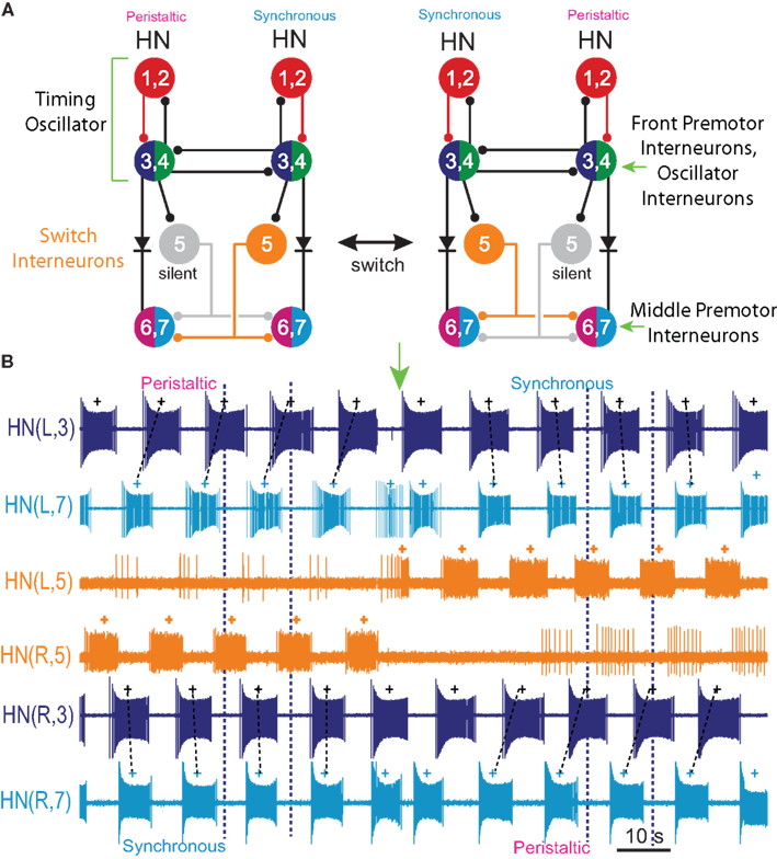
Figure 1. Circuit diagram and activity of the heartbeat central pattern generator (CPG) core. (A) Circuit diagram showing synaptic connections among interneurons of the core heartbeat CPG. The HN(3) and HN(4), and HN(6) and HN(7) interneurons are defined as the front and middle premotor interneurons respectively. Switches in coordination mode of the heartbeat CPG are associated with switches in which HN(5) interneuron (switch interneuron) is active (color – synchronous side) and which is silent (gray – peristaltic side). The two coordination modes are shown: left peristaltic/right synchronous and left synchronous/right peristaltic. It is often convenient to refer simply to the coordination on one side with the other side implied. Throughout, large colored circles are cell bodies and associated input processes. Lines indicate cell processes, small colored/black circles indicate inhibitory chemical synapses, and diodes indicate rectifying electrical junctions. For simplicity in the CPG diagrams cells with similar input and output connections and function are combined. (B) Activity in a bilateral pair of front [HN(3)] premotor interneurons, a bilateral pair of middle [HN(7)] premotor interneurons, and the bilateral pair of switch [HN(5)] interneurons of the core heartbeat CPG during a switch in coordination mode from left peristaltic to left synchronous in a typical extracellular recording. Note the precipitous reciprocal change in the switch interneurons from active to silent (with some sporadic firing) and vise versa at the vertical green arrow, which precipitously and reciprocally switches the phase of the premotor interneurons on the two sides from peristaltic to synchronous and vise versa. In this and all subsequent figures, marker symbols indicate the time of the middle spike for each burst. Normally the middle spike of an HN(4) interneuron is used as a phase reference to compute phase (see Materials and Methods), but in this experiment the HN(4) interneurons were not recorded. The dark blue vertical dashed lines indicate the firing phase of the peristaltic HN(3) interneuron to ease comparison of relative (unilateral) phase during the two coordination modes, and slanted dashed lines indicate phase differences between ipsilateral front [HN(3)] and middle [HN(7)] premotor interneurons corresponding to peristaltic (large HN(7) lead) and synchronous (small HN(7) lag) coordination modes. The switch is indicated with a vertical arrow. In such switches, the front premotor interneurons remain fixed in phase and the middle premotor interneurons shift their phase with respect to them (Calabrese, 1977; Norris et al., 2006). In this and all subsequent figures, the heart interneuron (HN) is indicated by midbody ganglion number (1–7), and, if necessary, body side (L or R). Standard color and marker codes are also applied in this and in all subsequent figures: red/diamond, HN(1,2) interneurons; blue/circle, HN(3) interneurons; green/asterisk, HN(4) interneurons; orange/open circle, HN(5) interneurons; magenta/triangle, HN(6) interneurons; cyan/square, HN(7) interneurons. Slanted dashed lines indicate the phase difference.
The oscillator interneurons (HN(3) and HN(4) pairs) are also premotor, making specific inhibitory synaptic connections with ipsilateral heart motor neurons (Norris et al., 2007a). The phase relations of these front premotor interneurons (Figure 1A) are fixed but the middle premotor interneurons [HN(6) and HN(7) pairs (Figure 1A)] on the two sides are phased differently with respect to the front premotor interneurons by intervening switch interneurons [HN(5) (Figure 1A)] (Norris et al., 2006). These switch interneurons receive ipsilateral inhibitory input from the front premotor interneurons (oscillator interneurons) and make bilateral inhibitory connections to the middle premotor interneurons. The middle premotor interneurons also receive electrical input (thought to be rectifying) from ipsilateral front premotor interneurons (Calabrese, 1977). Only one of the two switch interneurons is active in bursts at any time; the other is silent (Figure 1). The result is that on the side of the active (bursting) switch interneuron, the premotor interneurons fire in near synchrony, while on the side of the silent switch interneuron they fire in a distinct rear-to-front progression, leading to two different coordination modes of the two lateral heart tubes, left synchronous/right peristaltic and left peristaltic/right synchronous, respectively (Figure 1). It is convenient to speak of peristaltic and synchronous coordination modes, but it is important to realize that saying one side is peristaltic at any given time necessarily means that the other side is synchronous at the same time. Moreover, periodic changes (∼20–40 times the heartbeat period) in the activity pattern (silent vs. bursting) of the switch interneurons lead to periodic side-to-side changes in the coordination mode within the CPG by shifting the phase of middle premotor with respect to front premotor interneurons (Figure 1) (Norris et al., 2006). We infer from these regular switches that there are no permanent asymmetries in the heartbeat CPG, i.e., in its synaptic connections or in the intrinsic properties of its components neurons. The synaptic connections in the CPG core have been extensively characterized (Calabrese, 1977; Peterson, 1983a,b; Ivanov and Calarese, 2000, 2003, 2006a,b). Most importantly, the activity and phase relations of the interneurons in the CPG core have been exhaustively quantified and animal-to-animal variability determined (Norris et al., 2006). Therefore, we have target values for phase and duty cycle of all the component neurons to constrain our model of the CPG.
Overview of Principal Experiments and Findings
To reproduce experimentally observed phasing in our CPG model, we varied the strength of inhibitory synaptic and excitatory electrical input from the timing network to follower premotor interneurons. Neither inhibitory nor electrical input alone was sufficient to produce proper phasing on both sides, but instead a balance was required. Our model suggests that the different phasing of the two sides arises because the inhibitory synaptic and excitatory electrical inputs oppose one another on one side (peristaltic) and reinforce one another on the other (synchronous) (see below). Our search of parameter space defined by the strength of inhibitory synaptic and excitatory electrical input strength led to a CPG model that well approximates the experimentally observed phase relations. The strength values derived from this analysis constitute model predictions that we tested by measurements made in the living system. Further, variation of the intrinsic properties of follower interneurons showed that they too systematically influence phasing. We conclude that a combination of inhibitory synaptic and excitatory electrical input interacting with neuronal intrinsic properties can flexibly generate a variety of phase relations within a rhythmically active neuronal network.
Materials and Methods
We modeled a core part of the heartbeat CPG in medicinal leeches. This CPG core consists of heart (HN) interneurons from HN(R,1)–HN(L,7), which are indexed by body side (L or R) and midbody ganglion number (1–7). Recently we have identified two more pairs of heart interneurons in midbody ganglia 15 and 16; these neurons switch in time with the ipsilateral HN(6) and HN(7) interneurons but their connections from within the CPG are not currently well defined (Seaman and Calabrese, 2008; Wenning et al., 2008). Because they do not feedback (rear-directed axons) to the CPG core they were not considered. One unidentified heart interneuron pair called HN(R/L,X) because its ganglionic origin is unknown was also not considered since they have no known synaptic connections onto the HN(5), HN(6) and HN(7) interneurons that were the main subject of this study. Unless otherwise noted (e.g., Figure 8), model interneurons on the left side were always in the synchronous coordination mode while those on the right were in the peristaltic mode, so we dispensed with body side indexing and simply labeled the interneuron or motor neuron as synchronous or peristaltic.
General Modeling Strategy
The heart interneuron CPG model was implemented using GENESIS (GEneral NEural SImulation System) software (Bower and Beeman, 1998). The 14 heart interneurons (7 bilateral pairs) (Figure 1) in our model CPG were outfitted with intrinsic conductances and inhibitory synaptic conductances largely derived from biophysical studies (See Kristan et al., 2005 for a review.), however conductances for the rectifying electrical junctions linking ipsilateral premotor interneurons – the HN(3), HN(4), HN(6), and HN(7) interneurons – were only estimated from voltage recordings (Calabrese, 1977).
The network connectivity diagram of the heartbeat CPG model is given in Figure 1, illustrating the connections among the 14 heart interneurons. The timing network of the CPG (Figure 1A), consisting of the HN(1)–HN(4) interneurons, has been modeled in considerable detail (Hill et al., 2001, 2002; Jezzini et al., 2004), and we implemented the model of this timing network by Jezzini et al. (2004). Because of their similar connectivity and interaction with the oscillator interneurons of the third and fourth ganglia, coordinating heart interneurons of the first and second ganglia were combined and modeled as a single bilateral pair of intersegmental cables (multi-compartmental fiber models) for computational efficiency. For each coordinating heart interneuron model, we implemented a “two-site model” (Δf = 2.1; see Jezzini et al., 2004 for details) that includes inhibitory synaptic conductances and intrinsic conductances tuned for the primary spike initiation site to be located in the fourth ganglion. The oscillator heart interneurons of the third and fourth ganglia were modeled as single-compartment neurons with the appropriate intrinsic conductances, inhibitory synaptic conductances as originally described in Hill et al. (2001). Within the timing network the intersegmental conduction delays (20 ms per segment), the strengths of each synaptic input, and the estimated time course of synaptic plasticity, were obtained from averaged voltage-clamp recordings and modeled as before (Hill et al., 2001, 2002; Jezzini et al., 2004). The h-current maximum conductance ( ) used was 4.0 nS, corresponding to a free-run timing network cycle period of 9.3 s (Jezzini et al., 2004).
Each of the remaining six heart interneurons (three bilateral pairs) were modeled as single-compartment neurons with the appropriate intrinsic conductances, inhibitory synaptic conductances, and a conductance for the rectifying electrical junctions linking ipsilateral oscillator interneurons (also front premotor heart interneurons) – the HN(3) and HN(4) – with the middle premotor heart interneurons – HN(6) and HN(7) (Calabrese, 1977) (Figure 1A). The inhibitory synaptic input onto the middle premotor heart interneurons arises from the HN(5) switch heart interneurons that connect to them bilaterally.
Switch interneurons
The primary focus of this study is to investigate the mechanisms of phasing of the middle premotor interneurons. It was thus important to develop model HN(5) switch interneurons that would faithfully reproduce activity pattern of the living switch interneurons so that the model middle premotor interneurons would receive the proper pattern of inhibitory synaptic input. The switch interneurons are very different in their electrical properties from the other heart interneurons but are not favorable for voltage-clamp analysis of voltage-gated currents (Lu et al., 1999). We therefore developed a reduced activity-based single-compartment model of the switch interneurons [HN(5)] using four voltage-gated conductances that were tuned via a genetic algorithm (Houck et al., 1997; Tobin and Calabrese, 2006) to fit experimentally recorded burst, phase, and spike frequency characteristics (Gramoll et al., 1994; Lu et al., 1999). The four conductances include three from the model oscillator interneurons – INa (Fast Na+), IP (Persistent Na+), and IK1 (Delayed Rectifier) – and a boot-strapped fast activating, very slowly inactivating (τ = 21.3 s) outward current. In contrast to oscillator (front premotor) interneurons, switch interneurons fire only on the synchronous side and in bursts with an accelerating spike frequency. The tuned switch [HN(5)] model interneurons were able to reproduce these accelerating bursts (see HN(5) in Figures 2, 5 and 8). The synaptic inhibition onto the switch interneurons arising from the ipsilateral HN(3) and HN(4) interneurons was modeled with both spike-mediated and graded conductances with a constant delay of 1.6 s. This delay was implemented to align artificially the model switch interneuron’s phase with experimental recordings of its phase with respect to the timing network (Norris et al., 2006). We used the same model equations for these synapses as for the synapses between oscillator interneurons (Hill et al., 2001) but the maximal conductances ( and
and  ) were set to 60 nS and 30 nS respectively.
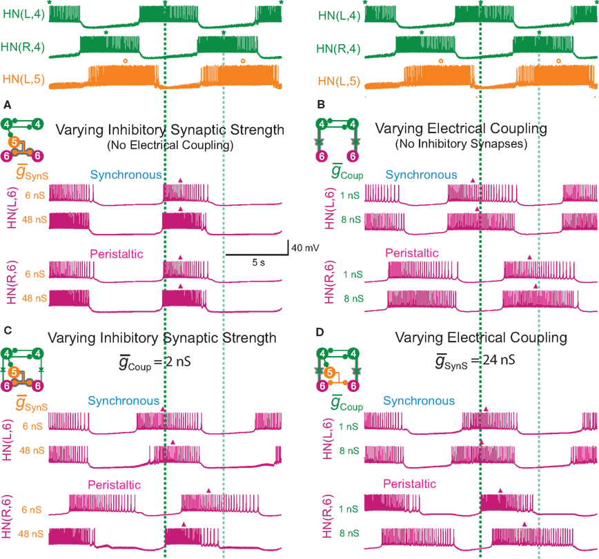
Figure 2. Inhibitory synaptic input ( ) and electrical coupling and (
 ) acting together can alter the phasing of the middle premotor interneurons. The CPG was simulated as described in Section “Materials and Methods” (left synchronous/right peristaltic) for parameter variations, but only activity of the HN(4) (front premotor), the active HN(5) switch interneurons, and the HN(6) (middle premotor) interneurons are illustrated. The phasing of the HN(4) and HN(5) interneurons is invariant across the variation of
  and
and  so they are illustrated only once at the top above each corresponding column of lettered panels (A–D). Vertical dashed lines (dark green HN(4) peristaltic, transparent green HN(4) synchronous) are dropped from the HN(4) interneurons to illustrate the phase differences between front and rear premotor interneurons. The insets indicate which inputs onto middle premotor interneurons were present and shadowing indicates which inputs were varied. (A,B) In the middle premotor interneurons, neither inhibitory synaptic input (
 ) nor electrical coupling (
 ) acting alone can alter their phasing as
  or
or  is varied. The phase of both the HN(6) bursts do not change appreciably when either
  or
or  alone are varied over an eight-fold range. (C,D) In the middle premotor neurons, when both inhibitory synaptic input (
 ) and electrical coupling (
 ) are present, varying either one (
 or
or  ) is sufficient to affect the phasing of the middle premotor interneurons. The phase of the HN(6) bursts do change appreciably, particularly on the peristaltic side (right) when either
  or
or  alone is varied over an eight-fold range in the presence of a constant value of the other. While not shown, the HN(7) neuron’s phase shows identical results with the HN(6) for the same variation of
  and
and  .
.
In addition to the synaptic inputs arising from the timing network, the peristaltic-side switch interneuron (silent) is tonically inhibited by a persistent leak current (reversal potential of −60 mV) that arises from unknown origins outside of the CPG (Gramoll et al., 1994; Lu et al., 1999). This current was modeled as an additional tonic leak conductance with a reversal potential of −60 mV and a maximum conductance ( ) of 15 nS. For Figure 8, this conductance was alternated across the two sides every 20–40 cycles as observed in the experimental preparation.
Middle premotor interneurons
The middle [HN(6) and HN(7)] premotor interneurons show similar activity to the [HN(3) and HN(4)] oscillator (front premotor) interneurons and were modeled similarly; they share the same complement of intrinsic conductances (Hill et al., 2001). All conductance parameters of the front and middle premotor interneurons were the same, except the leak-current maximum conductance and reversal potential of the middle premotor interneurons were chosen so that they were brought into an endogenous bursting regime ( : 9.9 nS, EL: −63.5 mV; (Cymbalyuk et al., 2002), and the h-current maximum conductance (
 : 2.0 nS) was tuned to give them a free-run cycle period of 8.1 s (87% of the timing network period). The current through the rectifying electrical junction from the front premotor interneurons was calculated as a constant multiplied by the difference between low-pass filtered voltage waveforms of the coupled interneurons (τ: 0.2 s) and restricted to pass only depolarizing current onto the middle premotor interneurons (the equations for such junctions are presented in Garcia et al., 2008). The synaptic inhibition onto the middle premotor interneurons arising from the HN(5) switch interneurons was modeled as being spike-mediated and showing short-term synaptic plasticity identical to the spike-mediated synaptic component of the synapses between oscillator interneurons (Hill et al., 2001) but the maximal conductance (
 ) was varied as described below.
Running Simulations and Parameter Searches
The model equations were integrated with an exponential Euler method using a time step of 0.0001 s for a sufficient period (≥10 s) to allow the model to settle and then data were recorded for 50–200 s. All complete bursts of the interneurons from the middle of the recording period were used in the analysis.
Due to the substantial computational time of modeling the entire CPG (especially the coordinating interneurons), all neurons within the heartbeat timing network were initially modeled fully and their relevant synaptic parameters (e.g., Vm, ICaS, and ICaF) for determining their inhibitory synaptic currents and junctional currents onto the interneurons of the fifth through seventh ganglia were recorded as a time series for 81.2 s of model time, corresponding to 10 full cycles of network activity. During the parameter searches, the timing network was no longer computed and this previously recorded time series data was “played-back” in a recurring loop of 10 cycles to the appropriate synaptic conductances to investigate the effects of these parameters on the middle heart interneurons. The ends of the loop were carefully spliced in order not to cause any abrupt changes in these parameters. This play-back saved an enormous amount of computational time and thus allowed us to pursue a more fine-grained analysis of the parameter space as evidenced in Figure 3. For all other model studies, all heart interneurons (including the entire timing network) were fully modeled with no play-back.
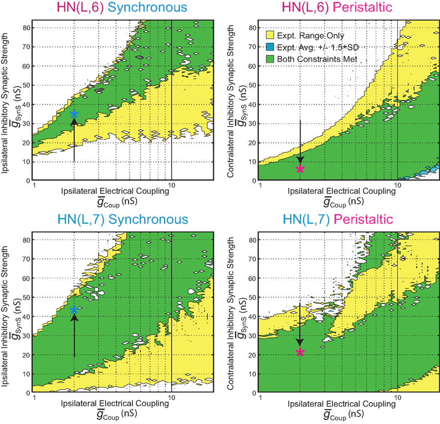
Figure 3. Covarying  and
and  to identify values for each middle premotor interneuron ipsilateral (left/synchronous) and contralateral (right/peristaltic) to the active (left/synchronous) HN(5) interneuron for which the model gave phasing and duty cycle appropriate to the living system. For every combination of
  and
and  , phase and duty cycle for that middle premotor interneuron were calculated and compared with that individual neuron’s experimentally recorded values (Norris et al., 2006). Two criteria were applied for displaying the data. If the model data fell within the experimental data range, it is indicated as a yellow region. If it fell within the experimental average ±1.5 × SD, it is indicated as a blue region. If both criteria were met, the regions were shown in green. If neither criterion was met, then the region was left blank. There are several small blank regions (white spots) inside regions where otherwise both criteria were met. Investigation of a random sub-set of these white spots indicated that they are regions where the calculated values barely missed one or both criteria. The cross-hatched white spots (upper left panel) were investigated in detail. For
  , we used 140 values ranging from 0.1 to 14 nS in 0.1-nS increments. These values were plotted on a log scale. For
  , we used 120 values ranging from 1 to 302 nS. The actual values used were 10 raised to the 0.00 to +2.48 power in increments of +0.02. This should give 125 inhibitory strength values rather than the 120 we used, but due to rounding on the low end several values came out as the same. Ultimately, we cropped all of the plots (1–11 nS,
  , 0–84 nS,
  ) in order to expand the regions where there was data that best met our criteria. Light blue (synchronous) and pink (peristaltic) asterisks indicate parameter values (i.e., canonical parameters) chosen for subsequent figures as indicated in the text.
In the parameter searches, we systematically varied the strength of synaptic inhibition ( ) from the switch interneurons and the electrical coupling from the front premotor interneurons onto the middle premotor interneurons (Figures 2 and 3) to investigate the role of synaptic coupling on the relative phasing and duty cycle of the middle premotor interneurons. The values of synaptic inhibition maximum conductance were varied from (
 ) 0.6 to 84 nS in 0.6 nS increments. Values of electrical coupling strength (
 ) were varied exponentially from 1 to 301 nS. In plotting the effects of these variations on phasing of the middle premotor interneurons, we plotted the electrical coupling parameter values on a logarithmic scale to enhance data separation at low conductances.
Model data analysis
Simulation data were analyzed for period, intraburst spike frequency, duty cycle and phase using the same methods for the corresponding data from the living system in Norris et al. (2007b). Briefly, custom analysis programs were written in MATLAB, and ≥10 full bursts of simulation data from a given model interneuron were analyzed for each data point. Data points reported are mean ± SD. Our burst marker for measuring period and phase was the middle spike of each burst. Our burst detection paradigm recognized a burst as groups of at least four spikes separated from other spikes by a minimum inter-burst interval of 300 ms.
We calculated bilateral (absolute) phase of the model heart motor neurons using the middle spike of the HN(4) premotor interneuron input pattern in the peristaltic coordination mode as our phase reference (assigned 0.0 phase with no standard deviation) in accordance with our convention for the living system (Norris et al., 2007b), thus facilitating comparisons between the model and the living system. We also calculated first and last spike phase for each burst and constructed bilateral phase diagrams as described in Norris et al. (2007b).
Experiment Verification of Model Predictions
Leeches (Hirudo sp) (Siddall et al., 2007) were obtained from commercial suppliers (Leeches USA, Westbury, NY, USA and Biopharm, Charleston, NC, USA) and maintained in artificial pond water at 15°C. After the animals were anesthetized in cold saline, chains of ganglia were dissected consisting of midbody ganglion 2 to at least midbody ganglion 8 (G2–G8) for recording the strength of the HN(5)-mediated IPSCs in the HN(6) and HN(7) middle premotor interneurons. The preparations were pinned (ventral surface up) in 60-mm Petri dishes lined with Sylgard™ 184 (Dow Corning, Midland, MI, USA). Ganglia in which heart interneurons were to be recorded were desheathed using fine scissors or microscalpels. The preparation was superfused continuously with normal leech saline containing (in mM): 115 NaCl, 4 KCl, 1.8 CaCl2, 10 glucose, 10 HEPES buffer, adjusted to pH 7.4 with NaOH, at 1–2 ml/min (bath volume 6–8 ml).
Extracellular and intracellular recording techniques
We used conventional electrophysiological procedures for leech neurons described in Norris et al. (2007b). For extracellular recordings from heart interneurons, we used suction electrodes filled with normal saline. Electrodes were pulled on a Flaming/Brown micropipette puller (P-97, Sutter Instruments, Novato, CA, USA) from borosilicate glass (1 mm o.d., 0.75 mm i.d., A.M. Systems) and placed in a suction electrode holder (E series, Warner Instruments Corp., Hamden, CT, USA). To ensure a tight fit between the cell and electrode, the electrode tips had a final inner diameter of ∼20 μM, approximately the diameter of a heart interneuron’s soma. The electrode tip was brought in contact with the cell body and light suction was applied using a syringe until the entire cell body was inside the electrode. Extracellular signals were monitored with a differential A.C. amplifier (model 1700, A-M Systems, Carlsborg, WA, USA) at a gain of 1000 with the low and high frequency cut-off set at 100 and 1000 Hz, respectively. Noise was reduced with a 60-Hz notch filter and a second amplifier (model 410, Brownlee Precision, Santa Clara, CA, USA) amplified the signal appropriately for digitization. Heart interneurons were identified based on soma size, soma location in the ganglion, and ultimately identified by their characteristic bursting activity (e.g., Figure 1B). The HN(5) switch interneurons are very difficult to identify and record extracellularly because their somatic spikes are small (∼5 mV recorded intracellularly). To aid our search, we always monitored an easily identified and recorded front premotor interneuron. Signal to noise ratios were often poor for the switch interneuron recordings, necessitating off-line filtering so that the spikes could be easily discerned and detected.
For intracellular recordings from middle premotor interneurons, we used sharp intracellular electrodes (∼20–30 MΩ filled with 4 M KAc, 20 mM KCl) and an Axoclamp-2B amplifier (Molecular Devices, Sunnyvale, CA, USA) operating in discontinuous current-clamp or discontinuous single electrode voltage-clamp mode with a sample rate of 2.5–2.8 kHz. The electrode potential was monitored to ensure that it settled during each sample cycle. Output bandwidth was 0.3 kHz. Voltage-clamp gain was 0.8 to 2.0 nA/mV. The voltage-clamp holding potential for recording spontaneous IPSCs in interneurons was −45 mV and for recording spontaneous spike-mediated coupling currents was −55 mV. At the end of each experiment the electrode was withdrawn from the neuron and only data in which the electrode potential was within ±5 mV of ground were included. Thus holding potentials were accurate within ±5 mV.
Data were digitized (5-kHz sampling rate) using a digitizing board (Digi-Data 1200 Series Interface, Axon Instruments, Foster City, CA, USA) and acquired using pCLAMP software (Axon Instruments) on a personal computer (PC).
Determining the strength of HN(5)-mediated IPSCs and HN(3) and HN(4)-spike-mediated coupling currents in the HN(6) and HN(7) middle premotor interneurons
To determine the strength of each inhibitory synaptic connection from a switch interneuron to a middle premotor interneuron, we recorded extracellularly from one (a minority of cases, n = 8) or both (n = 17) switch interneurons. We then voltage clamped as many of the middle premotor interneurons as possible in that preparation (−45-mV holding potential) one after another, recording spontaneous IPSCs for several interneuron burst cycles in each coordination mode, spanning several switches in the activity state of the switch interneuron (switches in coordination mode). N = 25 total preparations were used in these experiments. We then used off-line spike-triggered averaging during periods when the switch interneuron was in its active state. These spike-triggered averages gave us a direct measure of synaptic strength. When we recorded only one HN(5) switch interneuron we inferred the synaptic strength of its bilateral homolog in the same premotor interneuron, during the recorded switch interneuron’s silent state, by manually measuring and averaging the spontaneous rhythmic IPSCs phased with the activity of the monitored front premotor interneuron. For both spike-triggered and manually averaged IPSCs, we averaged over at least 10 spike bursts, and we ignored the first 5 and last 5 spikes in a burst. When both HN(5) switch interneurons were recorded, direct comparisons of spike-triggered averaged IPSCs were made.
To determine the strength of each electrical connection from a front premotor interneuron to a middle premotor interneuron, we recorded extracellularly from one (n = 23) or both (n = 5) front premotor interneurons. We then voltage clamped the ipsilateral middle premotor interneurons (−55 mV holding potential), recording spontaneous spike-mediated coupling currents for a minimum of 15 interneuron burst cycles. N = 28 preparations were used in these experiments. For averaging spike–mediated coupling currents, we averaged over at least 10 spike bursts, and we ignored the first 5 and last 5 spikes in a burst. To assess the impact of switches in coordination mode on the spike-mediated coupling currents, continuous voltage-clamp measurements were made across a minimum of two switches (n = 4). Synchronous and peristaltic coordination modes were compared with a pairwise, 2-tailed t-test.
Spike detection and IPSC/spike-mediated coupling current averaging were performed off-line using custom-made MATLAB software (Mathworks, Natick, MA, USA); see Norris et al. (2006, 2007a,b) for more details. The average strength of a connection was defined as the amplitude (measured from the preceding baseline current) of the largest peak of the spike-triggered average IPSC or spike-mediated coupling current.
Statistics
Mean values are presented ± standard deviation (SD) and in some cases the coefficient of variation (CV) expressed as a decimal fraction of the mean. Conductance and current measurements were subjected to single factor ANOVA to determine significant differences between effects. F statistic, df, and p are reported. Where appropriate, post hoc testing was done with Tukey’s HSD test. In cases where ANOVA was not appropriate, we performed paired t-tests (two-tailed). For all tests p < 0.05 was the criterion for significant difference.
Results
Model Strategy
We extended our existing model of the timing network (Jezzini et al., 2004) to construct a model of the heartbeat CPG core (Figure 1A). In our CPG model, we implemented known synaptic and neuronal properties. An activity-based model of the switch interneurons was constructed that was tuned to fit experimentally recorded burst and phase characteristics. The middle premotor interneurons show similar activity to and were modeled in the same manner as the front premotor (oscillator) interneurons.
To reproduce experimentally observed CPG phasing, we systematically varied the strength of inputs onto the middle premotor interneurons, i.e., inhibitory synapses from the switch interneurons and excitatory electrical coupling from the front premotor interneurons (Figure 1A). Once suitable strengths were determined we then varied the intrinsic properties of the middle premotor interneurons to determine their effects on activity characteristics.
The Effect of Inhibitory Synaptic Input and Excitatory Electrical Coupling on Phasing of the Middle Premotor Interneurons
First we determined whether inhibitory synaptic input from the switch interneurons,  , or excitatory electrical coupling from the front premotor interneurons,
  , alone could establish entrainment and appropriate phasing of the middle premotor interneurons (Figures 2A,B). HN(6) and HN(7) middle premotor interneurons were modeled with identical intrinsic properties. With a minimum of 6 nS for inhibitory synaptic maximal conductance (
 ) or 1 nS for electrical coupling conductance (
 ) stable entrainment of the middle premotor interneurons was established (Figures 2A,B). Beyond these threshold values, varying either over an eight-fold range in the absence of the other had no discernable effect on middle premotor interneuron phasing or duty cycle on either the peristaltic or synchronous side. With electrical input alone (
 ) both sides assume highly synchronous phasing between front and middle premotor interneurons. With inhibitory synaptic input (
 ) alone, the basic structure of the asymmetric peristaltic-synchronous pattern seen in the living system is established. The middle premotor interneurons lead the front premotor interneurons by a large phase difference on the peristaltic side, and the middle premotor interneurons slightly lag the front premotor interneurons in phase on the synchronous side very similar to the living system (c.f. Figure 5C). This observation highlights the primacy of the asymmetric activity in the switch interneuron pair in establishing the asymmetric coordination in the heartbeat CPG. To attain the smooth phase progression of middle and front premotor interneurons observed in the living system on the peristaltic side (c.f. Figure 5C), however, it is necessary to be able to generate phase differences intermediate between the large phase lead seen with only inhibition and the synchrony seen with only electrical coupling. We concluded that to establish appropriate peristaltic phasing of the middle premotor interneurons neither inhibitory synaptic nor excitatory electrical input alone would suffice.
Next we determined whether inhibitory synaptic input from the switch interneurons,  , in conjunction with excitatory electrical coupling from the front premotor interneurons,
  , could establish entrainment and appropriate phasing of the middle premotor interneurons (Figures 2C,D). We independently varied
  or
or  in the presence of a fixed suprathreshold amount (established above for entrainment) of the other (Figures 2C,D;
  and
and  respectively). Beyond the threshold values, varying either over an eight-fold range in the presence of the other had a monotonic effect on middle premotor interneuron phasing on both the peristaltic and synchronous side. Increasing
  caused the middle premotor interneurons to fire slightly later in phase on the synchronous side and earlier in phase on the peristaltic side. Increasing
  caused the middle premotor interneurons to fire slightly earlier in phase on the synchronous side and later in phase on the peristaltic side. Moreover, duty cycle also varied monotonically with variations of
  or
or  , decreasing with increasing
  on both sides and increasing with increasing
  on both sides, but more prominently on the peristaltic side. We concluded that it should be possible to obtain appropriate phasing and duty cycle for each of the middle premotor interneurons in either coordination mode by adjusting the balance of
  and
and  for each premotor interneuron in the two coordination modes.
We next systematically co-varied  and
and  and determined the phasing and duty cycle of the middle premotor interneurons on the two sides. We used 120 values in the range of 1–302 nS for
  and 140 values in the range 0.1–14 nS for
  and constructed 3-dimensional contour plots for phase and duty cycle (data not shown). We compared phase and duty cycle from these simulations to the living system for each of the middle premotor interneurons on the two sides (Figure 3). Then, the simulation data that matched well with both phase and duty cycle in the living system were combined into a single plot. These combined plots show where in the
  vs.
vs.  plane both phase and duty cycle were appropriate to the living system – within the experimentally observed range and/or within ±1.5 × SD of the mean of the living system (corresponding to 86.6% of expected normal data) for each middle premotor interneuron on the two sides (Norris et al., 2006). For each of the four plots, there is a broad area of the
  vs.
vs.  plane where both criteria are met.
Choosing Inhibitory Synaptic Input,  , and Excitatory Electrical Coupling,
  , to Obtain Appropriate Phasing and Duty Cycle of the Middle Premotor Interneurons
We looked for parameter pairs ( and
and  ) for each of the four premotor interneurons (HN(6) and HN(7) synchronous and HN(6) and HN(7) peristaltic) that would match well the living system (Figures 2C,D). Our main criteria for this match were the observed phasing and duty cycle of each of the middle premotor interneurons. Due to the regular switching between coordination modes in the living system, we also required that the parameters meet a symmetry constraint; connections made by left and right neurons of the same type are equal in strength. We then simplified the parameter choice further by making the electrical coupling relatively weak, based on the small size of recorded coupling potential/currents associated with “prejunctional” spikes (Calabrese, 1977; Seaman and Calabrese, 2008). These constraints led us to choose a value of
  = 2 nS, which we then applied to all the electrical connections. To find a suitable value for
  , we calculated for each of the four premotor interneurons the squared error of the phase and duty cycle and the sum of these squared errors with respect to the average values of the living system for each value of
  used in the analysis (Figure 3). We found the value of
  where this summed error was a minimum for each of the four premotor interneurons and plotted this point as an asterisk on each of the corresponding panels of Figure 3. These four points constitute a clear model prediction. To obtain appropriate phasing and duty cycle for the four middle premotor interneurons, the ipsilateral inhibitory connections of the switch interneurons must be stronger than their corresponding contralateral connections and the connections of the switch interneurons onto the HN(7) premotor interneurons must be stronger than their corresponding ipsilateral connections onto the HN(6) interneurons.
How Do Inhibitory Synaptic and Excitatory Electrical Input Interact to Produce Appropriate Phasing and Duty Cycle of the Middle Premotor Interneurons?
Using the values of  and
and  for each of the model middle premotor interneurons obtained in the analysis of Figure 3 (hereafter referred to as canonical parameters), we explored how inhibitory synaptic and electrical coupling currents interact in the intrinsically bursting middle premotor interneurons to produce appropriate phasing and duty cycle. The middle premotor interneurons were tuned as intrinsically bursting neurons with an intrinsic free-run cycle period of 8.1 s, which was 87% of the canonical timing network period of 9.34 s. Consequently, for stable entrainment of the middle premotor interneurons by the timing network to be effected, these premotor interneurons must be slowed during each cycle. Analysis of the synaptic and coupling currents that occur in these neurons during entrainment by the canonical timing network illuminate how phase and duty cycle are controlled (Figure 4A). It is important to note when viewing these records that the coupling conductance is always present but that currents flows only when there is a difference in potential between the two coupled neurons as when the HN(3) or HN(4) neurons produce spikes. In contrast, the synaptic conductance occurs only when the presynaptic HN(5) neuron produces a spike and the postsynaptic current will depend on the conductance amplitude and the driving force (Vm−ESynS).
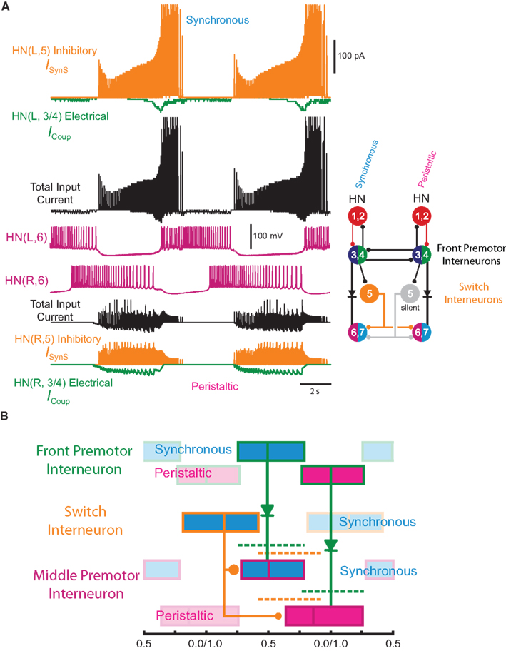
Figure 4. Exploration of our CPG model. (A) Inhibitory synaptic (ISynS) and electrical coupling (ICoup) current flowing in the HN(6) premotor interneurons, synchronous and peristaltic. With the canonical parameter ( and
and  ) values chosen in Figure 3, the total input current (black) to the synchronous HN(L,6) interneuron is dominated by the inhibitory synaptic current from the active HN(L,5) switch interneurons (orange). The electrical coupling current, ICoup, from the ipsilateral HN(L,3) and HN(L,4) front premotor interneurons (green) brings on firing in the HN(L,6) at the end of the inhibitory current, ISynS, from the switch interneuron but otherwise has little effect. Consequently, the HN(L,6) interneuron fires essentially in antiphase with the active HN(L,5) interneuron. The total input current (black) to the peristaltic HN(R,6) interneuron is a compromise between the inhibitory synaptic current, ISynS, from the active HN(L,5) switch interneuron (orange) and the electrical coupling current, ICoup, from the ipsilateral HN(L,3) and the HN(L,4) premotor interneurons (green) because of their extensive temporal overlap. At the end of the electrical coupling current from the ipsilateral front premotor interneurons, the inhibitory current terminates the HN(R, 6) burst, but in the absence of any input the HN(R,6) interneuron recovers and begins to fire approximately midway between input bouts, due to its intrinsic bursting properties. (B) Schema based on a phase diagram that illustrates how the appropriate phasing of the middle premotor interneurons is achieved in the CPG model. To emphasize a single cycle in the diagram all but one cycle is made transparent. Box fill color indicates coordination mode, synchronous (light blue) and peristaltic (pink) and box boundary colors [green HN(4), orange HN(5), magenta HN(6)] indicate the model interneuron. Middle spike phase (“phase”) is indicated by a vertical line in the box, while the first and last spike phases are indicated by the left and right boundaries of the box respectively. The dashed lines indicate the expected phasing if the middle premotor interneurons received only inhibitory input (ball scaled for relative strength) from the active switch interneuron (orange) or only electrical input (diode) from the front premotor interneurons (green). The measured phase of both middle premotor interneurons is a combination of these two inputs.
On the synchronous side, in the middle premotor interneurons, the strong inhibitory synaptic input from the switch interneurons arrives earlier than the electrical input from the front premotor interneurons and quickly terminates the ongoing burst in the HN(6) interneuron and delays the onset of the next burst (Figure 4A). When the electrical input does arrive, it generates sufficient initial inward current, however, to bring on the next HN(6) burst before the termination of the inhibitory input causing the initial part of the burst to seem ragged. Entrainment is achieved mainly through the delaying effect of strong inhibition. The situation is similar in the synchronous HN(7) interneuron – from the ipsilateral active switch interneuron in the HN(7) interneuron (43.2 nS) is comparable to
  in the HN(6) interneuron (34.8 nS) (Figure 3) – and so there is not much phase difference between these middle premotor interneurons.
On the peristaltic side, in the middle premotor interneurons, inhibitory synaptic and electrical input arrives nearly simultaneously and the corresponding currents that flow are balanced but with a steady inward bias, particularly in the HN(6) interneuron (Figure 4A) where  from the contralateral active switch interneuron is relatively small (6.0 nS) compared to
  in the peristaltic HN(7) interneuron (21.0 nS) (Figure 3). During entrainment, the middle premotor interneurons begin their burst in the absence of input due to their intrinsic bursting ability, and the mixed synaptic/coupling current prolongs their burst and delays the next burst onset. Because the peristaltic HN(7) interneuron receives more inhibitory current but the same excitatory coupling current, its bursts terminate earlier and begin earlier, i.e., it leads the peristaltic HN(6) interneuron in phase.
Using the canonical values of  and
and  the activity pattern of our CPG model and average data from the living system (Norris et al., 2006) are remarkably similar (Figure 5). The only detail that appears off in the model is that the bursts of the HN(6) and HN(7) interneurons are a bit prolonged with a low spike frequency tail at their end.
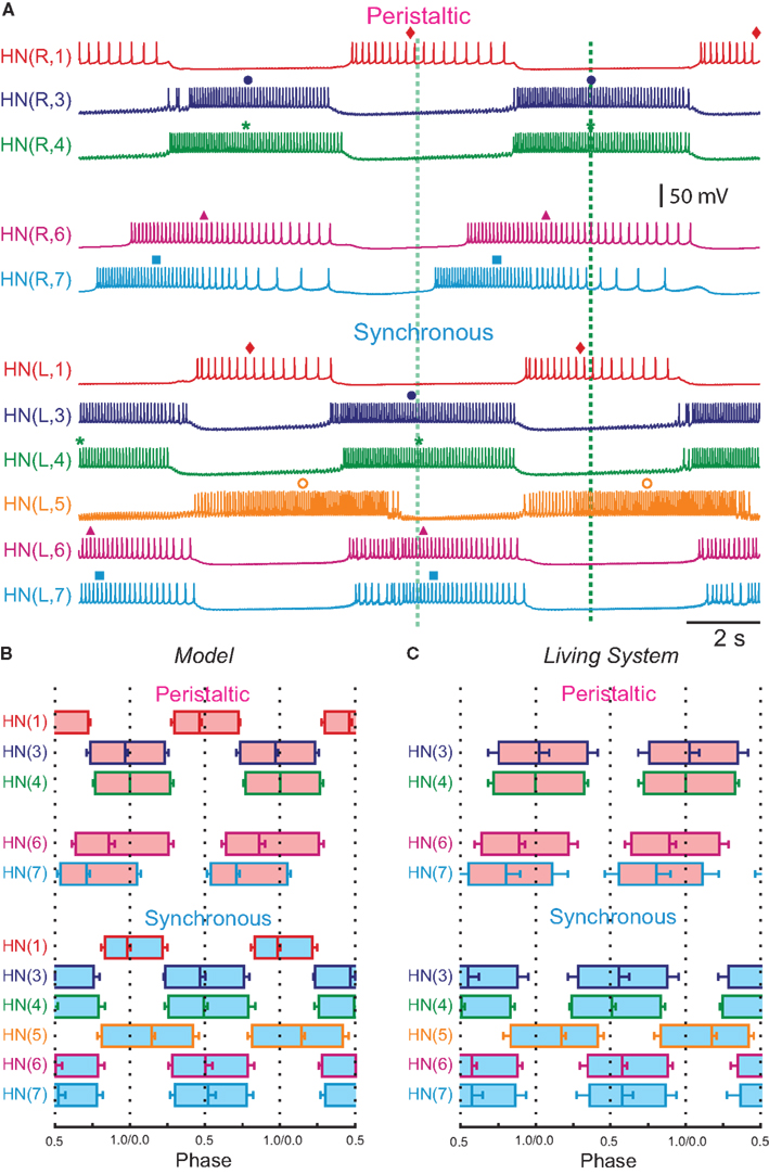
Figure 5. Model activity with the parameter ( and
and  ) values chosen from Figure 3: comparison to the living system. (A) Model recordings showing activity of all identified interneurons of the CPG core except the HN(2) coordinating interneurons, which are identical in activity to and lumped with the HN(1) interneurons (see Materials and Methods), and the inactive HN(5) switch interneuron. Top (R) traces show peristaltic activity and the bottom (L) traces show synchronous activity. The dark/light green dashed line indicates the firing phase of the peristaltic/synchronous HN(4) interneuron. (B) Phase diagram of model activity based on data from (A). (C) Phase diagram of living system activity from Norris at al. (2006). The phase diagrams give average first spike phase (left edge of each box), middle spike phase (middle line in each box – simply referred in the text as phase) and last spike phase (right edge of each box) all with SD (horizontal “error” bars). Box fill color shows coordination mode, synchronous (light blue) and peristaltic (pink) and box boundary colors [red HN(1,2), blue HN(3), green HN(4), orange HN(5), magenta HN(6), turquoise HN(7)] indicate the interneuron and correspond to trace colors in (A).
Figure 4B gives a conceptual framework for understanding how this realistic phasing of the middle premotor interneurons is achieved in the CPG model. In the middle premotor interneurons on the synchronous side, inhibitory synaptic and excitatory electrical input reinforce one another. The strong inhibitory synaptic input arrives earlier than electrical input and phasing is nearly the same as it would be with only the electrical excitation, because the excitation determines the time of burst onset (Figure 4B). Entrainment is established, however, mainly by the delaying effect on burst onset of the strong inhibitory current. In the middle premotor interneurons on the peristaltic side, the relatively weak inhibitory synaptic input and electrical input occur nearly simultaneously and thus oppose one another (Figure 4B). The weak inhibition cannot force the termination of the burst, which is thus extended by the excitation, and this extension of the burst establishes entrainment by delaying the next burst. On both sides, phasing is a compromise between the phase of entrainment with only the synaptic inhibition (orange dashed lines) or only the electrical excitation (green dashed lines) (Figure 4B). Specifically, in both coordination modes, the total burst activity phase (duty cycle) of the middle premotor interneurons completely overlaps the burst activity expected with electrical coupling alone, but on the peristaltic side the burst beginning (first spike phase) is advanced (as is middle spike phase) and the total activity phase (duty cycle) is correspondingly expanded.
How Do the Intrinsic Membrane Properties Affect Phasing in the CPG Model?
In a model with canonical values of  and
and  , we explored how intrinsic membrane properties, particularly those underlying the period of the timing network and of the intrinsic bursting of the middle premotor interneurons, affected entrainment and phasing of the middle premotor interneurons in the CPG model. Figure 6A shows how we varied these periods by varying h-current (
 ) in either the front (period of the timing network) or middle (intrinsic period of the middle premotor interneurons) premotor interneurons. Varying timing network period caused a monotonic change in phasing of middle premotor interneurons on both sides, and there was a limited range of timing network period where entrainment was established with middle premotor interneuron phasing appropriate to the living system (Figure 6B). Stable entrainment on the peristaltic side could not be achieved with timing network periods exceeding ∼13.5 s, and the timing network cannot be driven to periods shorter than ∼6 s. Appropriate middle premotor interneuron phasing for the two sides was limited to timing network periods in the range of ∼7 to ∼10 s, which is relatively close to the intrinsic burst period of the middle premotor interneurons of 8.1 s. The analysis shows that robust appropriate middle premotor interneuron phasing is possible either when the timing network has a longer or a shorter period than the intrinsic period of the middle premotor interneurons.
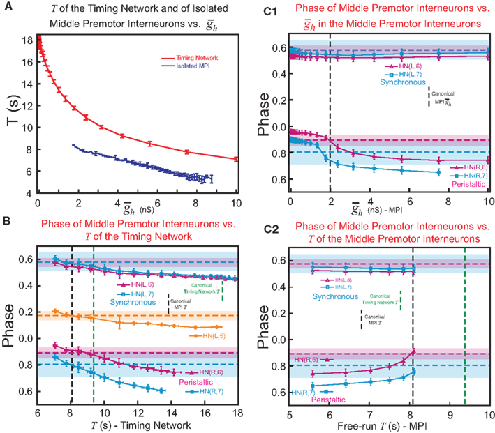
Figure 6. The effect of timing network period (T) and middle premotor interneuron intrinsic period (T) on the phasing of switch and middle premotor interneurons. (A) To vary the period of the timing network we varied the maximal conductance of h current,  , in the HN(3) and HN(4) oscillator interneurons simultaneously and to vary intrinsic period of the middle premotor interneurons (MPI) we varied the maximal conductance of h current,
  , in both the HN(6) and HN(7) middle premotor interneurons. The intrinsic period of a middle premotor interneuron was assessed in the absence of any input from the timing network or the switch interneurons. The blue curve describing the model premotor interneurons is truncated on the left because the model neurons became silent with low values of
  , and on the right because the model neurons became tonically active with high values of
  . (B) Varying the period of the timing network caused a monotonic change in the phasing of the HN(6) and HN(7) middle premotor interneurons on both the synchronous (L) and peristaltic (R) sides. Curves are truncated on the right when successful one-for-one entrainment of the switch or premotor interneurons by the timing network could no longer be maintained. (C1) Varying
  in the HN(6) and HN(7) middle premotor interneurons caused a monotonic change in their phasing on both the synchronous (L) and peristaltic (R) side that saturated at both high and low values of
  . (C2) Using data from (A) giving the dependence of the intrinsic period of middle premotor interneurons on
  , the data from (C1) was re-plotted to show the effect of intrinsic period of the premotor interneurons on their phasing. In (B,C1,2), data for each middle premotor interneuron, synchronous and peristaltic, is plotted separately using the neuronal symbols and color code. Horizontal dashed lines in a model neuron’s color code indicates the average phase observed in the living system and shading in a model neuron’s color code indicates the average phase ± 1.5 × SD observed in the living system. Vertical dashed lines indicate canonical cycle period values for the timing network (green) or the middle premotor interneurons (black, PMI).
Varying  in the middle premotor interneurons also caused a monotonic change in phasing of middle premotor interneurons on both sides that saturated at high as well as low values of
  on both sides, though the effect was more pronounced on the peristaltic side (Figure 6C1). When
  in the middle premotor interneurons is set below ∼1.7 nS, then the model interneurons no longer burst intrinsically but become silent (Figure 6A) and coordinated bursting is achieved solely by post-inhibitory rebound. When
  in the middle premotor interneurons is set above ∼8.7 nS, then the model interneurons no longer burst intrinsically but fire tonically (Figure 6A) and coordinated bursting is achieved by inhibitory sculpting. In Figure 6C2, the variation of
  in the middle premotor interneurons of Figure 6C1 is transformed into a variation in middle premotor interneuron intrinsic period. Figure 6C2 reveals that appropriate phasing is achieved on the peristaltic side only over a limited range of intrinsic burst periods, whereas appropriate phasing is achieved on the synchronous side over the entire range of intrinsic burst periods. We conclude that intrinsic properties of both the timing network and the middle premotor interneurons are important for establishing appropriate phase relations for the middle premotor interneurons. These properties should be matched appropriately with the strength of inhibitory synaptic and electrical excitatory input onto the middle premotor interneurons.
Testing Model Predictions
Given how important the values of  and
and  are in obtaining appropriate phasing of the model middle premotor interneurons (Figure 3), it seems appropriate to consider the canonical values of these parameters as model predictions. We tested these predictions by measuring in the living system the strength of the inhibitory synaptic currents evoked in middle premotor interneurons by ipsilateral and contralateral HN(5) interneurons and of spike-mediated coupling currents evoked in middle premotor interneurons by ipsilateral HN(3) and HN(4) interneurons (Figure 7). Specifically, the model predicts that (1) ipsilateral connections of the switch interneurons onto the middle premotor interneurons should be stronger than their corresponding contralateral connections and (2) connections of the switch interneurons onto the HN(7) middle premotor neuron should be stronger than corresponding connections onto the HN(6) middle premotor interneurons (Figure 3).
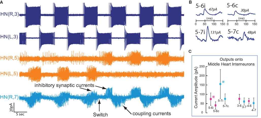
Figure 7. Testing model predictions from Figure 3. (A) Extracellular recordings from both HN(3) and HN(5) interneurons and a voltage-clamp recording from a HN(R,7) middle premotor interneuron. A switch is illustrated in which the left active switch interneuron becomes silent as the right silent switch interneuron becomes active. Note how the envelope of inhibitory synaptic currents increases in the HN(R,7) interneuron when the HN(R,5) interneuron becomes active while the envelope of coupling currents remains similar. (B) Spike-triggered average inhibitory synaptic currents in an HN(6) and an ipsilateral HN(7) heart interneuron evoked by both ipsilateral and contralateral HN(5) interneurons. Data are shown from the same preparation as in (A). (C) Combined data (mean ± SD) across N = 51 preparations showing similarity in size of all coupling currents in HN(6) (magenta) and HN(7) (turquoise) middle premotor interneurons from the ipsilateral HN(3) and HN(4) interneurons (right four data points; 3–6, 3–7, 4–6, 4–7) and significant differences (indicated by asterisks – see text) in the size of inhibitory synaptic currents mediated by ipsilateral (i) vs. contralateral (c) HN(5) interneurons in the HN(6) (magenta) and HN(7) (turquoise) middle premotor interneurons (left four data points; 5–6i, 5–6c, 5–7i, 5–7c). Significant differences were also observed in the size of synaptic currents in the HN(6) vs. the corresponding ipsilateral HN(7) interneuron (see text).
During switches in coordination mode recorded in voltage clamp in middle premotor interneurons, the size of the envelope of inhibitory synaptic currents was dramatically larger when the ipsilateral HN(5) interneuron was active than when the contralateral HN(5) interneuron was active (Figure 7A). This gross observation was corroborated by spike-triggered (or hand) averaged inhibitory synaptic currents, which in every case of a middle premotor interneuron thus recorded showed the inhibitory synaptic current from the ipsilateral HN(5) interneuron to be larger than that from the contralateral HN(5) interneuron (Figure 7B). Data combined across N = 25 preparations also showed for both the HN(6) and the HN(7) middle interneurons that the average inhibitory synaptic current from the ipsilateral HN(5) interneuron was significantly larger than from the contralateral HN(5) interneuron (Figure 8C) (HN(6) n = 11, p = 0.014; HN(7) n = 14, p = 0.011 – paired t tests). Moreover, the inhibitory synaptic currents evoked by the HN(5) interneurons in HN(6) interneurons were significantly smaller than in side-corresponding HN(7) interneurons (Single Factor ANOVA followed by post hoc testing using Tukey’s HSD – F = 11.99, df = 3, p = 0.00001. All post hoc pairwise comparisons were significant to p < 0.01 with Tukey’s HSD). These size relationships correspond well to the model “predictions” of Figure 3.
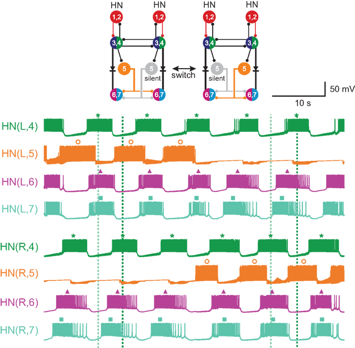
Figure 8. The phasing of the middle premotor neurons responds rapidly to a switch in coordination mode from left synchronous/right peristaltic to left peristaltic/right synchronous in the CPG model. This switch is illustrated in the top panel: the left active switch interneuron becomes silent as the right silent switch interneuron becomes active. The bottom panel shows recordings from one pair of front premotor interneurons, both pairs of middle premotor interneurons and the switch interneurons in the CPG model during this switch. Note the rapid readjustment of the phase of the middle premotor interneurons after the switch. The dark/light green dashed line indicates the firing phase of the peristaltic/synchronous HN(4) interneuron.
Moreover, during switches in coordination mode recorded in voltage clamp in middle premotor interneurons, the size of the envelope of spike-mediated coupling currents remained similar when the ipsilateral HN(5) interneuron was active or when the contralateral HN(5) interneuron was active (Figure 7A). This gross observation is expected given that there is no change in the sources or phase of this input during switches. Spike-triggered (or hand) averaged coupling currents in middle premotor interneuron thus recorded showed coupling currents from both the ipsilateral HN(3) and HN(4) interneurons to be similar (i.e., not significantly different) in both ipsilateral HN(6) and HN(7) middle premotor interneurons (data not shown). Combined data across N = 28 preparations also showed for both the HN(6) and the HN(7) middle interneurons that the average coupling currents from the ipsilateral HN(3) and HN(4) interneurons were similar (Figure 7C) (Single Factor ANOVA F = 1.42; df = 3, p = 0.259). These size relationships correspond well to the model “predictions” of Figure 3.
As can be seen from the standard deviation bars in Figure 7C, there was considerable animal-to-animal variation in the size of inhibitory synaptic and coupling currents measured in middle premotor interneurons. We observed that the strength of the inhibitory synapses varied over a nearly six-fold range from animal-to-animal and that the strength of electrical coupling varied over a nearly three-fold range from animal-to-animal. Ranges for inhibitory synapses were 28.5–131 pA for HN(5) to the ipsilateral HN(6), 21–73 pA for HN(5) to the contralateral HN(6), 47–278 pA for HN(5) to the ipsilateral HN(7), and 27–139 pA for HN(5) to the contralateral HN(7). Ranges for electrical coupling were 44.5–117 pA for HN(3) to HN(6), 38–84 pA for HN(4) to HN(6), 34–92.5 pA for HN(3) to HN(7), and 13–101.5 pA for HN(4) to HN(7). These ranges indicate that the living network arrives at different solutions to appropriate middle interneuron phasing, possibly within a framework like that of Figure 3.
In the living system, often a switch interneuron in the “silent” state fires weakly or sporadically (e.g., Figures 1 and 7). We used spike-triggered averaging to determine if these spikes in the silent state cause detectable IPSCs. In six different middle premotor interneurons (three HN(6) – one contralateral and two ipsilateral to the switch interneuron – and three HN(7) – one contralateral and two ipsilateral to the switch interneuron), we found no detectable IPSCs by spike-triggered averaging even when the silent switch interneuron was firing 10–20 spikes per burst at a frequency of 2 Hz. In other heart interneurons [e.g., HN(3) and HN(4)], spikes arising off a relatively hyperpolarized baseline are ineffective at causing transmitter release (Ivanov and Calabrese, 2003); presumably the same is true for switch interneurons in the silent, relatively hyperpolarized, state, and we need not consider such firing in our model.
Switches in Coordination Mode
Figure 8 shows an induced switch in coordination mode in our CPG model. Prior experimental work has shown that the inactive switch interneuron is silenced by the input of a tonic leak current of unknown origin (Gramoll et al., 1994). Halfway through the illustrated record the HN(L,5), which had been active was silenced with a steady leak current and simultaneously this leak was removed from the previously inactive HN(R,5) interneuron. Immediately prior to this imposed switch the premotor interneurons showed a phase relationship characteristic of the left synchronous/right peristaltic mode and immediately after this imposed switch the premotor interneurons assume a new stable phase relationship characteristic of the left peristaltic/right synchronous mode. Similar results were achieved in 10 different switches in both coordination mode directions within the same model run. We conclude that the model reestablishes appropriate phasing after switches within one cycle as in the living system (c.f. Figure 1).
Discussion
Within natural motor patterns and within the CPGs that produce them activity does not just assume simple in phase (0.0) and antiphasic (0.5) coordinations. All possible phase relationships may be appropriate for producing the proper sequences of motor neuron discharge; indeed in metachronal behaviors like undulatory swimming in lampreys (Grillner et al., 2007) and leeches (Kristan et al., 2005) and swimmeret beating in crayfish (Jones et al., 2003; Smarandache et al., 2009) a smooth intersegmental variation in phase leads to motor discharge in a multiplicity of phases. How can a CPG generate phases of activity intermediate between in phase, typically promoted by electrical coupling, and antiphase, typically promoted by moderate to strong inhibition? Our results suggest that a core network displaying canonical in phase and antiphase activity can produce any phasing required by balancing electrical coupling and synaptic inhibition as inputs to inherently bursting follower neurons.
We constructed a model of the core of the leech heartbeat CPG by extending an existing model of the CPG’s timing network (Hill et al., 2002; Jezzini et al., 2004). In the heartbeat CPG, premotor interneurons are coordinated differently on the two sides in peristaltic and synchronous modes that regularly and reciprocally switch sides (Figure 1A). Our model suggests that the different coordination modes (phasing) of the two sides arise because the inhibitory synaptic and excitatory electrical inputs onto middle premotor interneurons oppose one another on one side ( peristaltic) and reinforce one another on the other (synchronous). This asymmetry results from asymmetry in the activity of a bilateral pair of switch interneurons with bilateral inhibitory connections onto the middle premotor interneurons. One of the pair is active leading to synchronous coordination and the other is silent leading to peristaltic coordination (Figure 1B). In our model, to reproduce the details of the experimentally observed phasing on each side, we varied the strength of inhibitory synaptic input arising from the switch interneurons and excitatory electrical input arising from front premotor interneurons onto the middle premotor interneurons. Neither inhibitory nor electrical input alone was sufficient to produce proper phasing on both sides, but instead a balance was required. Our search of parameter space defined by the strength of inhibitory synaptic and excitatory electrical input strength led to a CPG model that well approximates the experimentally observed phase relations. The strength values derived from this analysis constitute model predictions that we tested and confirmed by measurements made in the living system. Further, variation of the intrinsic properties of middle premotor interneurons in the model showed that they too systematically influence phasing. We conclude that a combination of inhibitory synaptic and excitatory electrical input interacting with neuronal intrinsic properties can flexibly generate a variety of phase relations within a rhythmically active neuronal network.
Endogenous Bursting Gives More Flexibility in Achieving a Multitude of Phase Relations in Follower Neurons
It is interesting to note that we were not able to achieve experimentally observed phasing by the balancing mechanism we explored here if the follower interneurons were not inherently bursting. This was particularly true on the peristaltic side where inhibition and excitation are nearly in phase and thus opposed. Tonically spiking neurons tend to fire in response to electrical excitation and turn off whenever inhibited but bursting neurons (and we suspect neurons with strong rebound plateau properties) tend to have more fixed burst durations and defined inter-burst intervals that bring them into entrainment in a variety of phases dependent on the excitatory/inhibitory balance. The middle premotor interneurons do possess intrinsic bursting properties when isolated from inhibitory synaptic input with bicuculline (Cymbalyuk et al., 2002). The neuron models used for the middle premotor interneurons have been extensively studied for their inherent bursting properties and are dominated by the inactivation and de-inactivation time constants of a slowly inactivating Ca current that supports bursting (Hill et al., 2001, 2002; Cymbalyuk et al., 2002; Olypher et al., 2006). These time constants restrict the burst duration and inter-burst interval and fit well the requirements for entrainment at a variety of phases given the period of the entraining timing network. As Figure 6B shows, the inherent period of the entraining timing network can be either faster or slower than the inherent burst period of the follower middle premotor interneurons and still achieve appropriate phasing. Nevertheless, there are period limits for appropriate phasing and one-to-one entrainment.
With endogenously bursting follower neurons, like the model middle premotor interneurons we used, the excitatory drive associated with electrical coupling appears more effective than even strong inhibition at establishing the phasing of the follower neuron. Consider Figure 4B; very strong inhibition as on the synchronous side barely moves the phase from what would be established by the electrical coupling alone. Even when inhibition and electrical coupling are opposed as on the peristaltic side, phasing is still closer to what would be established by electrical coupling alone despite the inhibition being stronger in terms of current (Figure 4A). This observation suggests that electrical coupling is more effective at synchronizing bursting neurons than inhibition.
Implications for Animal-to-Animal Variability Observed in the Leech Heartbeat CPG
The subject of animal-to-animal variability in intrinsic membrane and synaptic parameters and their implication for network activity has received considerable attention, particularly in the crustacean stomatogastric ganglion CPGs (Prinz et al., 2004; Bucher et al., 2005; Marder et al., 2007; Goaillard et al., 2009). The leech heartbeat CPG shows similar variability in its synaptic parameters (Figure 7) (Marder et al., 2007; Norris et al., 2007a; Seaman and Calabrese, 2008). The phasing of the middle premotor interneurons is quite variable between animals, particularly the HN(7) interneuron (peristaltic HN(6) phase = 0.893 ± 0.043; synchronous HN(6) phase = 0.578 ± 0.035; peristaltic HN(7) phase = 0.802 ± 0.094; synchronous HN(7) phase = 0.581 ± 0.072, Norris et al., 2006); correspondingly the motor pattern shows considerable phase variability as does the constriction pattern of the hearts (Norris et al., 2007b). Our parameter variations of Figure 3 show that the observed phase variability of the middle premotor interneurons is easily accounted for by the observed variability in inhibitory synaptic strength and electrical coupling (Figure 7). Moreover, simple changes in parameters that determine the intrinsic membrane properties of model neurons can traverse the entire criterion range of middle premotor interneuron phases as shown in Figure 6C1. These comparisons point out the importance of building neuronal network models that can accommodate observed animal-to-animal variability in output. Our model of the leech heartbeat CPG was able to reproduce such variability in output through variation of model parameters that correspond to experimentally observed variability in synaptic strengths; in this sense our model is a resounding success.
Conflict of Interest Statement
The authors declare that the research was conducted in the absence of any commercial or financial relationships that could be construed as a potential conflict of interest.
Acknowledgments
This work was supported by the NIMH APA DPN predoctoral fellowship 5 T06 MH to Rebecca C. Roffman, NIH Postdoctoral Fellowship Grant GM00680 to Adam L. Weaver and by NIH Grant NS24072 to Ronald L. Calabrese. We thank Jesse Hanson and Anne-Elise Tobin for discussions on how best to implement the genetic algorithm for fitting the switch interneuron model. We also thank Dr. Angela Wenning for countless critical discussions and help with data analysis and figure preparation.
References
Bose, A., Manor, Y., and Nadim, F. (2004). The activity phase of postsynaptic neurons in a simplified rhythmic network. J. Comput. Neurosci. 17, 245–261.
Bower, J. M., and Beeman, D. (1998). The Book of GENESIS: Exploring Realistic Neural Models with the GEneral NEural SImulation System, 2nd Edn. New York: Springer-Verlag.
Bucher, D., Prinz, A. A., and Marder, E. (2005). Animal-to-animal variability in motor pattern production in adults and during growth. J. Neurosci. 25, 1611–1619.
Calabrese, R. L. (1977). The neural control of alternate heartbeat coordination states in the leech, Hirudo medicinalis. J. Comp. Physiol. 122, 11–143.
Cropper, E. C., Evans, C. G., Hurwitz, I., Jing, J., Proekt, A., Romero, A., and Rosen, S. C. (2004). Feeding neural networks in the mollusc Aplysia. Neurosignals 13, 70–86.
Cymbalyuk, G. S., Gaudry, Q., Masino, M. A., and Calabrese, R. L. (2002). Bursting in leech heart interneurons: cell-autonomous and network-based mechanisms. J. Neurosci. 22, 10580–10592.
De Schutter, E., Ekeberg, O., Kotaleski, J. H., Achard, P., and Lansner, A. (2005). Biophysically detailed modelling of microcircuits and beyond. Trends Neurosci. 28, 562–569.
Garcia, P. S., Wright, T. M., Cunningham, I. R., and Calabrese, R. L. (2008). Using a model to assess the role of the spatiotemporal pattern of inhibitory input and intrasegmental electrical coupling in the intersegmental and side-to-side coordination of motor neurons by the leech heartbeat central pattern generator. J. Neurophysiol. 100, 1354–1371.
Goaillard, J. M., Taylor, A. L., Schulz, D. J., and Marder, E. (2009). Functional consequences of animal-to-animal variation in circuit parameters. Nat. Neurosci. 12, 1424–1430.
Gramoll, S., Schmidt, J., and Calabrese, R. L. (1994). Switching in the activity state of an interneuron that controls coordination of the hearts in the medicinal leech (Hirudo medicinalis). J. Exp. Biol. 186, 157–171.
Grillner, S., Kozlov, A., Dario, P., Stefanini, C., Menciassi, A., Lansner, A., and Hellgren Kotaleski, J. (2007). Modeling a vertebrate motor system: pattern generation, steering and control of body orientation. Prog. Brain Res. 165, 221–234.
Hill, A. A., Lu, J., Masino, M. A., Olsen, O. H., and Calabrese, R. L. (2001). A model of a segmental oscillator in the leech heartbeat neuronal network. J. Comput. Neurosci. 10, 281–302.
Hill, A. A., Masino, M. A., and Calabrese, R. L. (2002). Model of intersegmental coordination in the leech heartbeat neuronal network. J. Neurophysiol. 87, 1586–1602.
Hooper, S. L., Buchman, E., Weaver, A. L., Thuma, J. B., and Hobbs, K. H. (2009). Slow conductances could underlie intrinsic phase-maintaining properties of isolated lobster (Panulirus interruptus) pyloric neurons. J. Neurosci. 29, 1834–1845.
Hooper, S. L., and DiCaprio, R. A. (2004). Crustacean motor pattern generator networks. Neurosignals 13, 50–69.
Houck, C. R., Joines, J. A., Kay, M. G., and Wilson, J. R. (1997). Empirical investigation of the benefits of partial Lamarckianism. Evol. Comput. 5, 31–60.
Ivanov, A. I., and Calabrese, R. L. (2000). Intracellular Ca2+ dynamics during spontaneous and evoked activity of leech heart interneurons: low-threshold Ca currents and graded synaptic transmission. J. Neurosci. 20, 4930–4943.
Ivanov, A. I., and Calabrese, R. L. (2003). Modulation of spike-mediated synaptic transmission by presynaptic background Ca2+ in leech heart interneurons. J. Neurosci. 23, 1206–1218.
Ivanov, A. I., and Calabrese, R. L. (2006a). Graded inhibitory synaptic transmission between leech interneurons: assessing the roles of two kinetically distinct low-threshold Ca currents. J. Neurophysiol. 96, 218–234.
Ivanov, A. I., and Calabrese, R. L. (2006b). Spike-mediated and graded inhibitory synaptic transmission between leech interneurons: evidence for shared release sites. J. Neurophysiol. 96, 235–251.
Jezzini, S. H., Hill, A. A., Kuzyk, P., and Calabrese, R. L. (2004). Detailed model of intersegmental coordination in the timing network of the leech heartbeat central pattern generator. J. Neurophysiol. 91, 958–977.
Jones, S. R., Mulloney, B., Kaper, T. J., and Kopell, N. (2003). Coordination of cellular pattern-generating circuits that control limb movements: the sources of stable differences in intersegmental phases. J. Neurosci. 23, 3457–3468.
Krahl, B., and Zerbst-Boroffka, I. (1983). Blood pressure in the leech Hirudo medicinalis. J. Exp. Biol. 107, 163–168.
Kristan, W. B. Jr., Calabrese, R. L., and Friesen, W. O. (2005). Neuronal control of leech behavior. Prog. Neurobiol. 76, 279–327.
Lu, J., Gramoll, S., Schmidt, J., and Calabrese, R. L. (1999). Motor pattern switching in the heartbeat pattern generator of the medicinal leech: membrane properties and lack of synaptic interaction in switch interneurons. J. Comp. Physiol. A 184, 311–324.
Mamiya, A., and Nadim, F. (2004). Dynamic interaction of oscillatory neurons coupled with reciprocally inhibitory synapses acts to stabilize the rhythm period. J. Neurosci. 24, 5140–5150.
Marder, E., and Bucher, D. (2007). Understanding circuit dynamics using the stomatogastric nervous system of lobsters and crabs. Annu. Rev. Physiol. 69, 291–316.
Marder, E., Bucher, D., Schulz, D. J., and Taylor, A. L. (2005). Invertebrate central pattern generation moves along. Curr. Biol. 15, R685–699.
Marder, E., and Calabrese, R. L. (1996). Principles of rhythmic motor pattern generation. Physiol. Rev. 76, 687–717.
Marder, E., Tobin, A. E., and Grashow, R. (2007). How tightly tuned are network parameters? Insight from computational and experimental studies in small rhythmic motor networks. Prog. Brain Res. 165, 193–200.
Masino, M. A., and Calabrese, R. L. (2002a). Period differences between segmental oscillators produce intersegmental phase differences in the leech heartbeat timing network. J. Neurophysiol. 87, 1603–1615.
Masino, M. A., and Calabrese, R. L. (2002b). Phase relationships between segmentally organized oscillators in the leech heartbeat pattern generating network. J. Neurophysiol. 87, 1572–1585.
Mouser, C., Nadim, F., and Bose, A. (2008). Maintaining phase of the crustacean tri-phasic pyloric rhythm. J. Math. Biol. 57, 161–181.
Norris, B. J., Weaver, A. L., Morris, L. G., Wenning, A., Garcia, P. A., and Calabrese, R. L. (2006). A central pattern generator producing alternative outputs: temporal pattern of premotor activity. J. Neurophysiol. 96, 309–326.
Norris, B. J., Weaver, A. L., Wenning, A., Garciá, P. A., and Calabrese, R. L. (2007a). A central pattern generator producing alternative outputs: pattern, strength and dynamics of premotor synaptic input to leech heart motor neurons. J. Neurophysiol. 98, 2983–2991.
Norris, B. J., Weaver, A. L., Wenning, A., Garciá, P. A., and Calabrese, R. L. (2007b). A central pattern generator producing alternative outputs: phase relations of leech heart motor neurons with respect to premotor synaptic input. J. Neurophysiol. 98, 2992–3005.
Olsen, O. H., and Calabrese, R. L. (1996). Activation of intrinsic and synaptic currents in leech heart interneurons by realistic waveforms. J. Neurosci. 16, 4958–4970.
Olypher, A. V., Cymbalyuk, G., and Calabrese, R. L. (2006). Hybrid systems analysis of the control of burst duration by low-voltage-activated calcium current in leech heart interneurons. J. Neurophysiol. 96, 2857–2867.
Peterson, E. L. (1983a). Generation and coordination of heartbeat timing oscillation in the medicinal leech. I. Oscillation in isolated ganglia. J. Neurophysiol. 49, 611–626.
Peterson, E. L. (1983b). Generation and coordination of heartbeat timing oscillation in the medicinal leech. II. Intersegmental coordination. J. Neurophysiol. 49, 627–638.
Prinz, A. A., Bucher, D., and Marder, E. (2004). Similar network activity from disparate circuit parameters. Nat. Neurosci. 7, 1345–1352.
Seaman, R. C., and Calabrese, R. L. (2008). Synaptic variability and stereotypy in the leech heartbeat CPG. Abstr. - Soc. Neurosci. 371.7/MM7.
Siddall, M. E., Trontelj, P., Utevsky, S. Y., Nkamany, M., and Macdonald, K. S. (2007). Diverse molecular data demonstrate that commercially available medicinal leeches are not Hirudo medicinalis. Proc. Biol. Sci. 274, 1481–1487.
Smarandache, C., Hall, W. M., and Mulloney, B. (2009). Coordination of rhythmic motor activity by gradients of synaptic strength in a neural circuit that couples modular neural oscillators. J. Neurosci. 29, 9351–9360.
Stein, P. S. (2005). Neuronal control of turtle hindlimb motor rhythms. J. Comp. Physiol. A Neuroethol. Sens. Neural. Behav. Physiol. 191, 213–229.
Thompson, W. J., and Stent, G. S. (1976). Neuronal control of heartbeat in the medicinal leech. I. Generation of the vascular constriction rhythm by heart motor neurons. J. Comp. Physiol. 111, 261–279.
Tobin, A. E., and Calabrese, R. L. (2006). Endogenous and half-center bursting in morphologically inspired models of leech heart interneurons. J. Neurophysiol. 96, 2089–2106.
Wenning, A., Cymbalyuk, G. S., and Calabrese, R. L. (2004a). Heartbeat control in leeches. I. Constriction pattern and neural modulation of blood pressure in intact animals. J. Neurophysiol. 91, 382–396.
Keywords: neuronal networks, entrainment, neuronal oscillators
Citation: Weaver AL, Roffman RC, Norris BJ and Calabrese RL (2010) A role for compromise: synaptic inhibition and electrical coupling interact to control phasing in the leech heartbeat CPG. Front. Behav. Neurosci. 4:38. doi: 10.3389/fnbeh.2010.00038
Received: 04 February 2010;
Paper pending published: 14 April 2010;
Accepted: 03 June 2010;
Published online: 12 July 2010
Edited by:
Kathleen A. French, University of California San Diego, USAReviewed by:
Michael Nussbaum, University of Pennsylvania, USAWilliam Kristan, University of California San Diego, USA
Copyright: © 2010 Weaver, Roffman, Norris and Calabrese. This is an open-access article subject to an exclusive license agreement between the authors and the Frontiers Research Foundation, which permits unrestricted use, distribution, and reproduction in any medium, provided the original authors and source are credited.
*Correspondence: Ronald L. Calabrese, Department of Biology, Emory University, 1510 Clifton Road N.E., Atlanta, GA 30322, USA. e-mail: ronald.calabrese@emory.edu