 Jesus Mediavilla Varas* M. Philippens S. R. Meijer A. C. van den Berg P. C. Sibma J. L. M. J. van Bree D. V. W. M. de Vries
- Physical Protection and Survivability, Netherlands Organization for Applied Scientific Research, Rijswijk, Netherlands
Shock tube experiments and simulations are conducted with a spherical gelatin filled skull–brain surrogate, in order to study the mechanisms leading to blast induced mild traumatic brain injury. A shock tube including sensor system is optimized to simulate realistic improvised explosive device blast profiles obtained from full scale field tests. The response of the skull–brain surrogate is monitored using pressure and strain measurements. Fluid–structure interaction is modeled using a combination of computational fluid dynamics (CFD) simulations for the air blast, and a finite element model for the structural response. The results help to understand the physics of wave propagation, from air blast into the skull–brain. The presence of openings on the skull and its orientation does have a strong effect on the internal pressure. A parameter study reveals that when there is an opening in the skull, the skull gives little protection and the internal pressure is fairly independent on the skull stiffness; the gelatin shear stiffness has little effect on the internal pressure. Simulations show that the presence of pressure sensors in the gelatin hardly disturbs the pressure field.
1 Introduction
Blasts or explosions are the most common mechanisms of injury in modern warfare (Cernak and Noble-Haeusslein, 2009). The incidence of blast induced mild traumatic brain injury (mTBI) has increased dramatically in recent wars, mainly due to the increase use of improvised explosive devices (IED’s) and the improvements in protective equipment, which have decreased the mortality rate. Typical symptoms of troops exposed to blast induced mTBI are memory and cognitive deficits, as irritability, anxiety, fatigue, and headaches. The mechanisms responsible for blast induced mTBI are very complex (Säljö et al., 2011), including direct interaction with the head through the skull and/or head rotation; and interaction between chest and central nervous system through large blood vessels (Cernak and Noble-Haeusslein, 2009; Scherer and Schubert, 2009). The transfer of external blast through the skull into the brain is not known in such detail to develop injury criteria which will allow quantification of the risk on brain injury resulting from blast, and eventually design protective measures (e.g., helmets), as well as improve diagnostics.
To investigate the causes leading to blast induced mTBI, blast experiments on animals have been conducted, either using shock tubes (Long et al., 2009; Alley et al., 2011), explosives (Axelsson et al., 2000), or weapons (Säljö et al., 2008). Testing living animals is controversial due to ethical issues. The mechanical properties of living brain tissue decay very quickly with time (Garo et al., 2007), and hence testing cadavers is not representing reality correctly. As an alternative, blast tests on biofidelic surrogates can be performed (Alley et al., 2011; Zhu et al., 2011), with the limitations that they tend to be too simplistic, and the mechanical properties may differ from the actual head/body they represent. To investigate the complex wave propagation mechanisms leading to mTBI, a combination of experiments and numerical modeling is highly recommended. This enables to: (i) avoid a trial-and-error approach, involving large-scale use of laboratory animals, head surrogates, shock tube experiments, etc; (ii) study a spectrum of blast wave conditions that lead to the onset of mTBI; (iii) understand the brain response related to geometry, skull openings, through different structures of skull, brain, etc; (iv) analyze experimental data. The blast air flow around a human head (helmet) has been studied using Computational Fluid Dynamics (CFD) models (Mott et al., 2008). Fluid–structure interaction (FSI) between blast explosion and human head has been modeled using a combination of Eulerian and Lagrangian models (Chafi et al., 2009; Moore et al., 2009; Moss et al., 2009; Taylor and Ford Corey, 2009; Grujicic et al., 2010). In (Zhu et al., 2011), FSI simulations of shock tube blast experiments on a small surrogate were modeled using a combination of multimaterial arbitrary Lagrangian Eulerian (MMALE) for the air and Lagrangian model for the surrogate, coupled by means of a penalty formulation.
The goal of this investigation is to understand the interaction (reflection/transmission) between a blast wave and the human head. Similar to (Zhu et al., 2011), shock tube blast experiments and simulations are combined. A simplified spherical human head size skull–brain surrogate is used, which is exposed to a typical IED blast load. FSI is modeled using an uncoupled approach, a CFD model for the blast in the shock tube, and a Lagrangian finite element (FE) model for the surrogate response. The structure of this study is as follows: Section 2 discusses the experiments and simulations; the results are presented in Section 3, followed by a discussion and conclusions in Section 4.
2 Materials and Methods
The shock tube and the design of the IED blast is discussed in Section 2.1, followed by a description of the surrogate and the measurement devices 2.2, and the numerical model in Section 2.3.
2.1 Reproducing an IED Blast Profile
Far field explosions can be reproduced by means of shock tube experiments, which allow testing living (sedated) animals or surrogates. Shock tubes have the advantage over explosives that the blast profile is more reproducible, and allow to more easily perform measurements. The two most critical components of the wave pressure profile which describe the potential of a wave to cause injury to personnel, or damage to structures, are the maximum overpressure and the duration of the positive phase, Figure 1. In a biological material (e.g., brain tissue), the negative phase under pressure could potentially lead to cavitation. The effect of a blast explosion on the human head is a FSI problem, where part of the air shock wave is reflected against the skull, and part is transmitted through the brain internal structures, causing mTBI.
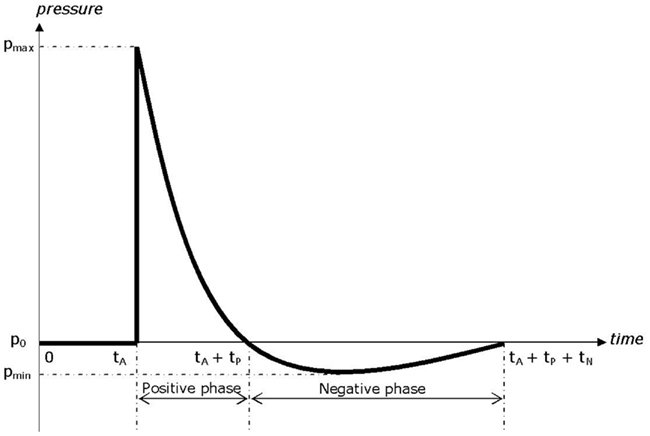
Figure 1. Typical blast pressure-time curve (Friedlander curve).
A shock tube consists of a driver section and a driven section. The driver section is pressurized and is separated from the driven section by means of a membrane. When the membrane is perforated, it triggers a shock wave, which moves away from the driver section. The original blast tube used at TNO for this experiments has a cross section of 0.4 m × 0.4 m and a total length of 17.6 m, Figure 2A. The shock tube has a transparent section for high speed photography, Figure 2B. It is able to generate a blast wave with a maximum peak pressure of 70 kPa, with a positive phase duration of about 40 ms. This phase duration is much too long for an IED. Data with IED experiments are collected and translated in a lethality model, which represents Bass’ lethality model (Bass et al., 2008) and an auditory injury model (Richmond and Axelsson, 1990). Figure 3 presents in what range the IED data are to be expected. A representative IED pressure profile should have a peak pressure in the range of 10–200 kPa and a positive phase duration in the range of 4–10 ms. The pressure-time blast profile depends on the tube dimensions and driver unit, the gas type, and is highly sensitive to the exact location in the tube. Hence, to obtain such a short phase duration, the original shock tube design was modified, by replacing the original driver section by a smaller driver section (1.2 l) and placing the object closer to the membrane (6 m). The result is a peak pressure and positive phase duration of 40 kPa and 6 ms, which has been used throughout the experimental campaign reported in this study.
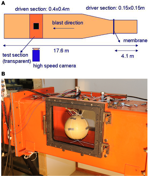
Figure 2. Shock tube. (A) Sketch and dimensions; (B) transparent section with surrogate.
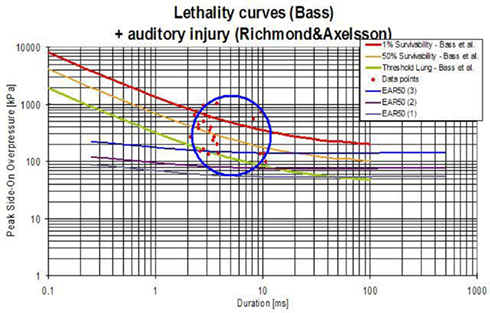
Figure 3. Representative IED and lethality curve. Data from IED experiments presented in a lethality model (Bass et al., 2008) and an eardrum rupture model (Richmond and Axelsson, 1990). The IED data points are presented by the red dots (in the circle).
2.2 Simplified Skull–Brain Surrogate: Measurements
A spherical human head size skull–brain surrogate is exposed to a representative IED shock tube generated blast. The sphere (“skull”) is made of modified bone-like Synbone1 polyurethane (PR0110 Generic hollow sphere), 7 mm thick, with a 0.19-m external diameter, and a 0.04-m diameter opening. The sphere is filled up with 10% mass ballistic three gelatin (brain stimulant). It is suspended inside the shock tube by means of strings, which keep it in place, Figure 2B. Endevco 8530B-2002 pressure gages (see detail in Figure 17), with an eigen frequency of 750 kHz, are used to measure the air pressure, P1, and P8; and gelatin pressure, P2, P3, and P4. P1 is situated on the skull, opposite to the opening; P8 is placed inside the shock tube, on one of the shock tube walls, at 0.1 m in front of the skull; P3, P2, and P4 are placed in the gelatin, aligned with a 0.03-m spacing, and perpendicular to the blast direction (side-on). See gages’ locations in Figure 4. Four strain gages TML YFLA-103 (length 10 mm, resistance 120 Ω, gage factor 2.1) are placed on the skull in orthogonal directions, as shown in Figure 4. A Pacific 58004 data acquisition system is used (2 MHz sample speed; 350 kHz anti-aliasing filter).
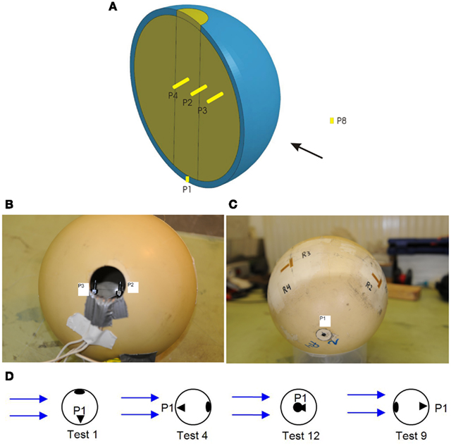
Figure 4. (A) Sketch of sphere section and pressure gages in gelatin: P2, P3, and P4 and air: P1, P8; (B) skull with pressure gages: P3 and P2; (C) strain gages: R1–R4; (D) opening orientation with respect blast direction in different tests: top(test 1), rear (test 4), front (test 9), side (test 12).
The influence of the opening is studied, and compared with a skull where the opening is closed. To measure the influence of the opening orientation with respect to the blast direction in the gelatin, the sphere is rotated, so that the opening is on top (test 1), at the rear (test 4), in front (test 9), and sideways (test 12).
From the blast experiments, the following observations have been made:
• The pressure and impulse (area under pressure-time curve) in the gelatin is higher when there is an opening in the skull, Figure 5A.
• The pressure in the gelatin depends on the opening orientation. The pressure is maximum when the opening faces the blast (test 9), and it is minimum when the opening is opposite to the blast (test 4), Figure 5B.
• The pressure wave speed is  calculated from the time the pressure wave takes to travel between two consecutive pressure gages (Δt = 2.05·10−5 s) and their spacing (Δx = 0.03 m), Figure 5C.
• Surprisingly, the initial pressure in the gelatin becomes negative (in the first 0.5 ms); after which it follows the surrounding air pressure within the tube. The reason for this pressure drop might be due to the experimental setup, since a new series of experiments did not show this effect.
• The strain rate on the skull is moderate, less than 10 s−1, Figure 6. Hence strain rate dependent behavior should be moderate.
• Closed skull experiments have shown that the internal pressure depends on the blast orientation. This indicates that the skull might not be fully closed or that there might be air trapped inside. Indeed, the skull is closed by sealing off the opening of an originally open skull using a Synbone cap. Although great care is exercised when gluing the cap, there must be a certain amount of leakage penetrating in the gelatin.
• Experiments have shown little influence of the pressure gage direction, side-on, or face-on.
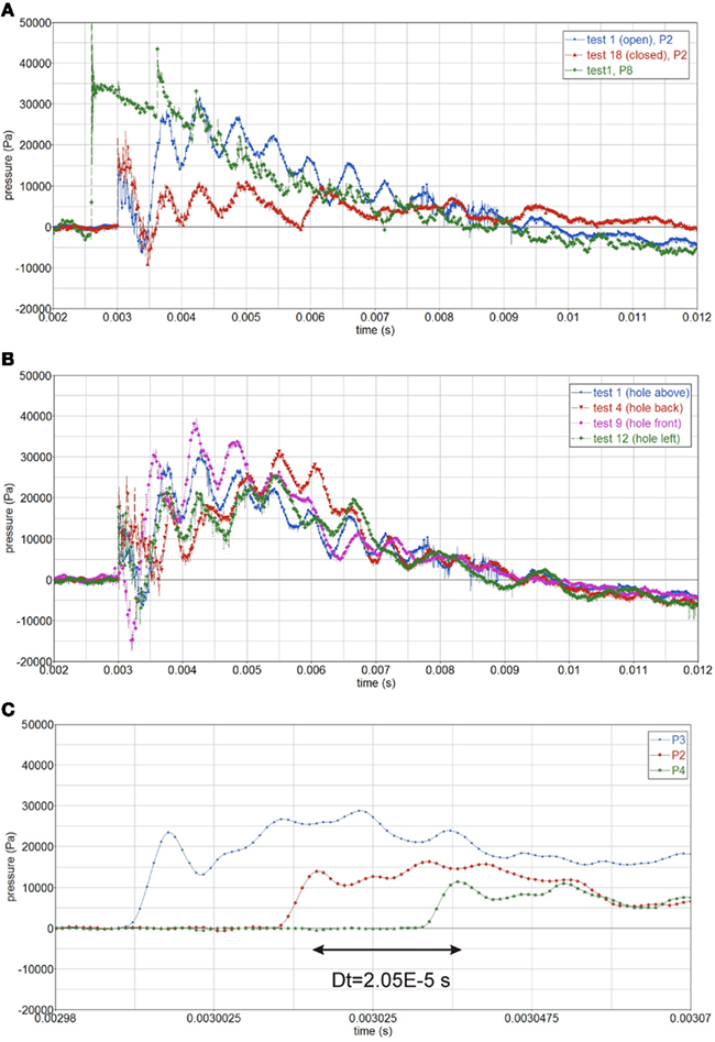
Figure 5. (A) Pressure in gelatin for open and closed skull, P2, and air pressure, P8; (B) influence of opening orientation on internal pressure, P2, open skull; (C) calculating the pressure wave speed, cp = 1463 m/s.
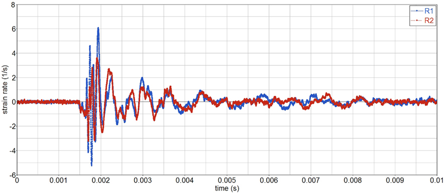
Figure 6. Strain rate history on the skull.
2.3 Numerical Model
Simulations of the above described shock tube experiments have been performed. FSI between air blast and surrogate is modeled in an uncoupled manner. The air blast is modeled by means of Eulerian CFD model, and the surrogate’s structural response is modeled using a Lagrangian FE model. This uncoupling is reasonable due to the small deformations and displacements of the surrogate during the blast loading. As reference case, the skull with the opening on top is investigated, test 1.
The air blast is simulated using the TNO BLAST code (van den Berg, 2009). Compressible inviscid flow of an ideal gas is described by the Euler conservation equations for mass, momentum, and energy. Due to symmetries, only one quarter of the tube is modeled. The computational domain has dimensions 5 m × 0.2 m × 0.2 m3, discretized as a uniform grid of 0.005 m grid spacing. The sphere is modeled as a fixed boundary. Appropriate initial boundary conditions have been applied to describe the incident blast.
The structural response is modeled using the FE code LS-DYNA. Only one half of the sphere is modeled due to symmetry using appropriate boundary conditions, Figure 7A. The geometry is modeled using roughly 43500 eight-node reduced integrated solid elements. The maximum element dimensions range from le = 0.002 m at the center, to le = 0.012 m outside, which is sufficient to describe the wave propagation. A minimum of six elements are needed within the wave propagation length λ, which is the case, i.e., 6le = 0.07 m < λ = 0.19 m (see Section 3). Three elements are used through the skull thickness. The simulated CFD pressure around the sphere is applied as boundary conditions at the perimeter element faces, Figure 7B.
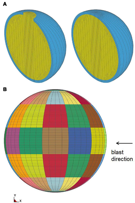
Figure 7. (A) FE mesh of open and closed skull; (B) element faces where pressure is applied, each color is a group, corresponding to the same output point of the CFD model.
The gelatin is modeled as an elastic material with a density of 960 kg/m3. The compression wave speed has been calculated, cp = 1463 m/s (see Section 2.2). A shear wave speed cs = 40 m/s has been adopted from literature (Papazoglou et al., 2006). From cp and cs the elastic constants have been worked out using Eq. 1, which yield G = 1.552E4 Pa, K = 2.076E9 Pa, E = 4.656E4 Pa, and ν = 0.4999963. The static stiffness of the Synbone skull has been measured from uniaxial tensile tests, E = 1.4E9 Pa, which is in agreement with values reported in literature (Cronin et al., 2000); ν = 0.469, and the density is 700 kg/m3. The compression wave speed and shear wave speed of the Synbone material is cp = 3415 m/s and cs = 825 m/s respectively.
3 Results
CFD simulations of the shock tube blast tests show the complex interaction, between the air shock wave (traveling at roughly 400 m/s), the sphere, and the shock tube, Figure 8. The pressure-time curves at different locations around the sphere are shown in Figure 9A. The highest peak reflected pressure and impulse occurs at the sphere’s front face. Compared with the experiments, the simulations slightly overpredict the impulse, Figure 9B.
Figure 8. Sequence of contour plots during the passage of the air shock wave. Snapshot interval Δt = 0.00015 s.
Figure 9. (A) CFD simulated pressure around the sphere; (B) CFD simulations and experiments of air pressure at sphere’s front face.
As indicated above, the test case considered is with the top opening, test 1. The reflected pressure of the CFD simulations, is applied as boundary conditions of the FE model. Figure 10 shows pressure contour plots of the open and closed skull at the same time (t = 0.008 s). Experiments and simulations show that when there is an opening, a larger impulse is transferred inside the gelatin, compared with the case with no opening, Figure 11. Yet, the simulations do not show the initial pressure drop, which is observed in the experiments. After this initial drop, both measured and simulated gelatin pressure follow the surrounding air pressure in the shock tube, decaying gradually to the atmospheric pressure after 7 ms.
Figure 10. Pressure contour plots for open (left) and closed skull (right), at t = 0.008 s.
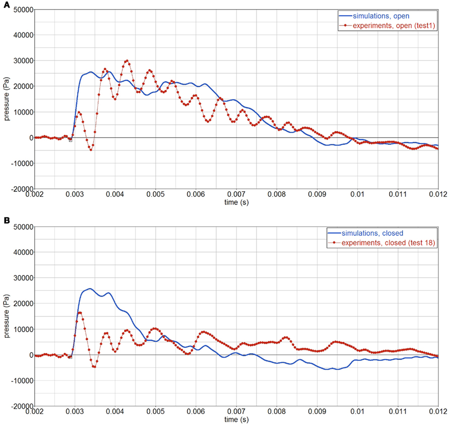
Figure 11. Experimental and simulated pressure history in the gelatin, P2. Signals are filtered using a 4-kHz filter. (A) open skull; (B) closed skull.
Simulations show a high frequency component,  which corresponds to the time the pressure wave takes to travel across the sphere, T = D/cp = 0.19/1463 = 0.00013 s. The wave length is equal to sphere diameter, λ = cp·T = D = 0.19 m. For clarity, this high frequency component has been eliminated throughout the analysis using a 4-kHz filter, Figure 12. The reason why this high frequency component is not seen in the experiments is not yet understood.
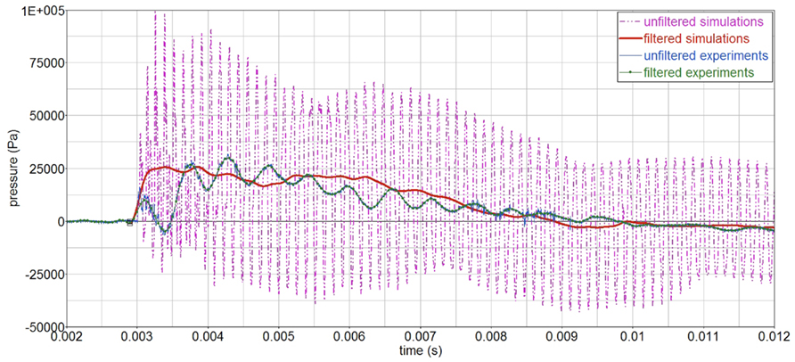
Figure 12. Filtered (4 kHz filter) and unfiltered pressure-time curves in the gelatin, P2.
As far as the strains on the skull, Figure 13, the amplitudes of simulations and experiments are similar, although the vibration period of the simulations is slightly longer, which indicates an overly soft behavior.
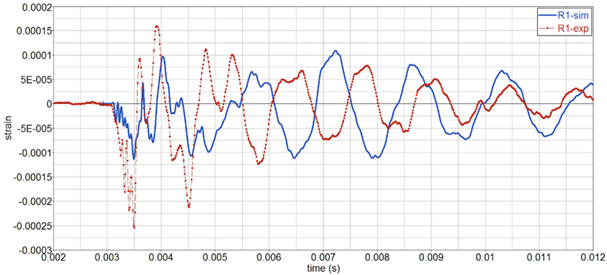
Figure 13. Filtered and unfiltered pressure signals in the gelatin, P2.
3.1 Parameter Study
To study the influence of the material properties on the surrogate’s response, a parameter study is performed. Firstly, the influence of the gelatin shear stiffness investigated, by varying the shear wave speed cs, while keeping the pressure wave speed cp constant. The corresponding elastic constants are given in Table 1. The simulations, Figure 14, show that the gelatin pressure varies little with cs, in the range of study, 4–30 m/s.
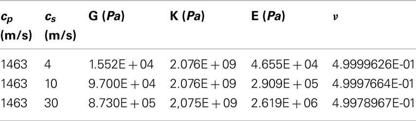
Table 1. Pressure and shear wave speeds, and elastic constants of gelatin.
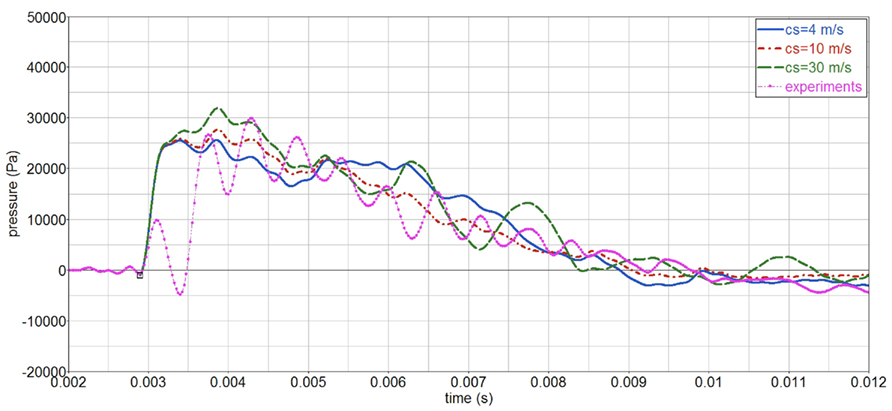
Figure 14. Influence of gelatin shear wave speed cs on the gelatin pressure, P2.
Secondly, the influence of the skull stiffness E is analyzed for an open and a closed skull. The normal Young’s modulus Eo = 1.4E9 Pa is varied between E = 0.1Eo (soft skull), to E = 10Eo (hard skull), and it is also compared with the case without skull (only gelatin). The open skull simulations show that the skull gives little protection, as the pressure in the gelatin is similar regardless of the skull stiffness, Figure 15. The skull stiffness mainly affects the initial part of the pressure-time curve. On the contrary, a closed skull does protect the gelatin inside, since the internal pressure is more sensitive to the skull stiffness. In the closed case, the skull is the only pathway of the stress waves into the gelatin; whereas in the open case, stress waves can also be transmitted through the opening. Hence the larger stiffness sensitivity for the closed skull.
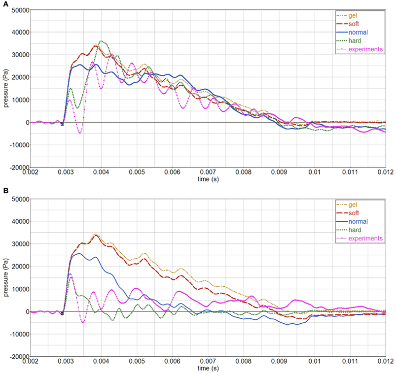
Figure 15. Influence of skull stiffness on gelatin pressure, P2. (A) open skull; (B) closed skull.
Strain rates in the gelatin are smaller than 3, 1/s, and maximum values are independent of the skull stiffness, Figure 16. Frequency does increase with increasing skull stiffness. Since the strain rates are moderate, no special measurement techniques, e.g., split hopkinson bar (SPB), are needed in order to characterize its strain rate behavior.
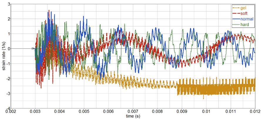
Figure 16. Influence of skull stiffness on gelatin strain rate (open skull).
3.2 Influence of Pressure Gages
It has been argued that gages may distort the surrounding pressure field because of their different impedance with respect the medium in which they are embedded (i.e., gelatin). Hence, the measured pressure may be different than the actual pressure, i.e., without gage interference. To study this effect, an Endevco pressure gage, Figure 17, has been modeled inside the surrogate. The gage has a mass of 2.3 g, a volume of 5 cc, and is made of stainless steel. Due to the gage, a full 3D model is used, made by mirroring the existing half symmetric model. The pressure gage is modeled by assigning appropriate material properties to a number of elements, which occupy roughly the same volume as the actual gage. The simulated gage has an equivalent density ρ = 4500 kg/m3 and steel elastic constants E = 2.1E11 Pa, ν = 0.3. Hence, cp = 7925 m/s and cs = 4237 m/s. The results show almost no influence of the gage when using a 4-kHz filter, Figure 18; a change in amplitude is visible when a 8-kHz filter is used.
Figure 17. (A) Endevco pressure gage; (B) full surrogate FE model with gage.
Figure 18. Influence of the gage on pressure-time curves, in the middle of sphere (P2). (A) 4 kHz filter; (B) 8 kHz filter.
4 Discussion and Conclusion
To understand the causes leading to blast induced mTBI, and eventually develop protective measures, the mechanisms of wave propagation in the human head must be investigated. As shown in this paper, shock tube blast tests on simple skull/brain surrogates, complemented with simple numerical models, can be very useful to find trends, and serve as basis upon which more advance surrogates-models can be devised. In the future, to be able to predict mTBI, animal testing, and simulations thereof must be done.
From this study, it can be concluded that:
• The presence of an opening in the skull and its orientation has a large influence on the results. Experiments and simulations show that the pressure and impulse transmitted to the gelatin increases with an opening. The maximum internal pressure occurs when the opening faces the blast. The internal pressure in the gelatin follow the outside air pressure. Experiments, however, show an initial pressure drop in the gelatin, not seen in the simulations, which must be caused by the experimental setup, since more recent measurements did not show this phenomenon. The presence of air bubbles near the pressure gages have not been checked, and these could affect the measurements.
• Simulations show that the effect of the skull stiffness is small if there is an opening in the skull, contrary to what happens with a closed skull. If the skull is closed, the blast pressure can only by transmitted to the gelatin through the skull; there is no alternative path through the opening.
• The gelatin shear wave speed has a small effect on the gelatin pressure, indicating a predominant bulk behavior. Hence, using a viscoelastic shear model, instead of the elastic material model used in this study, might only lead to a modest improvement.
• Because of the small deformation and displacement of the surrogate skull upon blast loading, an uncoupled simulation approach (CFD + FE) for the FSI between air blast and surrogate is justifiable. The CFD simulations agree with the shock tube blast experiments, with the advantage over the experiments that the pressure can be obtained anywhere in the domain, whereas the number of experimental measurements is limited.
• A high frequency component is observed in the simulated internal pressure, which corresponds to the reflections of the pressure wave against the sphere’s free boundaries. This effect is not seen in the experiments, and further investigation is needed to explain these differences. To the author’s knowledge there is no evidence in literature of the application of the pressure gages used in the experiments to viscoelastic materials. Hence, it is recommended to validate the gages’ performance in gelatin, under a known pressure-time load.
• Simulations revealed that the influence of the gages is limited and only introduces a high frequency component. Mesh fineness remains to be investigated, since the pressure field created around the gages may require a finer mesh discretization.
• Strain rates observed in the simulations and experiments are moderate. Hence, standard tests can be performed for material characterization (e.g., dynamic tensile tests), without the need of high strain rate tests (e.g., SHB).
Conflict of Interest Statement
The authors declare that the research was conducted in the absence of any commercial or financial relationships that could be construed as a potential conflict of interest.
Acknowledgments
The authors would like to thank TNO, in particular the department of Physical Protection and Survivability, for providing the framework to do the experiments and the simulations; as well as the Dutch Ministry of Defense for funding this research project.
Footnotes
References
Alley, M. D., Schimizze, B. R., and Son, S. F. (2011). Experimental modeling of explosive blast-related traumatic brain injuries. Neuroimage 54(Suppl. 1), S45–S54.
Axelsson, H., Hjelmqvist, H., Medin, A., Persson, J. K. E., and Suneson, A. (2000). Physiological changes in pigs exposed to a blast wave from a detonating high-explosive charge. Mil. Med. 165, 119–126.
Bass, C. R., Rafaels, K. A., and Salzar, R. S. (2008). Pulmonary injury risk assessment for short-duration blasts. J. Trauma 65, 604–615.
Cernak, I., and Noble-Haeusslein, L. J. (2009). Traumatic brain injury: an overview of pathobiology with emphasis on military populations. J. Cereb. Blood Flow Metab. 30, 255–266.
Chafi, M. S., Karami, G., and Ziejewski, M. (2009). Numerical analysis of blast-induced wave propagation using fsi and ale multi-material formulations. Int. J. Impact Eng. 36, 1269–1275.
Cronin, D. S., Salisbury, C., Worswick, M. J., Pick, R. J., Williams, K. V., and Bourget, D. (2000). “Appropriate material selection for surrogate leg models subjected to blast loading,” in Proceedings Explomet 2000, eds L. Murr and M. Meyer Albuquerque, NM.
Garo, A., Hrapko, M., Van Dommelen, J. A. W., and Peters, G. W. M. (2007). Towards a reliable characterisation of the mechanical behaviour of brain tissue: the effects of post-mortem time and sample preparation. Biorheology 44, 51–58.
Grujicic, M., Bell, W. C., Pandurangan, B., and He, T. (2010). Blast-wave impact-mitigation capability of polyurea when used as helmet suspension-pad material. Mater. Des. 31, 4050–4065.
Long, J. B., Bentley, T. L., Wessner, K. A., Cerone, C., Sweeney, S., and Bauman, R. A. (2009). Blast overpressure in rats: recreating a battlefield injury in the laboratory. J. Neurotrauma 26, 827–840.
Moore, D. F. Jr.,usalem, A., Nyein, M., Noels, L., Jaffee, M. S., and Radovitzky, R. A. (2009). Computational biology – modeling of primary blast effects on the central nervous system. Neuroimage 47(Suppl. 2), T10–T20.
Moss, W. C., King, M. J., and Blackman, E. G. (2009). Skull flexure from blast waves: a mechanism for brain injury with implications for helmet design. Phys. Rev. Lett. 103, 108702.
Mott, D. R., Schwer, D. A., Young, T. R., Levine, J., Dionne, J.-P., Makris, A., and Hubler, G. (2008). “Blast-induced pressure fields beneath a military helmet,” in MABS, Oslo.
Papazoglou, S., Rump, J., Klatt, D., Hamhaber, U., Braun, J., and Sack, I. (2006). “Influence of the transducer near field in MR elastography wave images,” in International Society of Magnetic Resonance in Medicine, Seattle, Washington.
Richmond, D. R., and Axelsson, H. (1990). Air blast and underwater blast studies with animals. J. Trauma 6(Suppl. 2), 229–234.
Säljö, A., Arrhen, F., Bolouri, H., Mayorga, M., and Hamberger, A. (2008). Neuropathology and pressure in the pig brain resulting from low-impulse noise exposure. J. Neurotrauma 25, 1397–1406.
Säljö, A., Mayorga, M., Bolouri, H., Svensson, B., and Hamberger, A. (2011). Mechanisms and pathophysiology of the low-level blast brain injury in animal models. Neuroimage 54(Suppl. 1), S83–S88.
Scherer, M., and Schubert, M. (2009). Traumatic brain injury and vestibular pathology as a comorbidity after blast exposure. Phys. Ther. 89, 980–992.
Taylor, P. A., and Ford Corey, C. (2009). Simulation of blast-induced early-time intracranial wave physics leading to traumatic brain injury. J. Biomech. Eng. 131, 061007.
van den Berg, A. C. (2009). “Blast”: a compilation of codes for the numerical simulation of the gas dynamics of explosions. J. Loss Prev. Process Industries 22, 950–4230.
Zhu, F., Wagner, C., Dal Cengio Leonardi, A., Jin, X., VandeVord, P., Chou, C., Yang, K., and King, A. (2011). Using a gel/plastic surrogate to study the biomechanical response of the head under air shock loading: a combined experimental and numerical investigation. Biomech. Model. Mechanobiol. 1–13. 1617–7959.
Keywords: mTBI, traumatic brain injury, finite element, blast, shock tube, surrogate, IED, CFD
Citation: Mediavilla Varas J, Philippens M, Meijer SR, van den Berg AC, Sibma PC, van Bree JLMJ and de Vries DVWM (2011) Physics of IED blast shock tube simulations for mTBI research. Front. Neur. 2:58. doi: 10.3389/fneur.2011.00058
Received: 14 February 2011;
Accepted: 28 August 2011;
Published online: 19 September 2011.
Edited by:
Marten Risling, Karolinska Institutet, SwedenReviewed by:
Johan Davidsson, Chalmers University of Technology, SwedenSvein Kleiven, Kungl Tekniska Högskolan, Sweden
Copyright: © 2011 Mediavilla Varas, Philippens, Meijer, van den Berg, Sibma, van Bree and de Vries. This is an open-access article subject to a non-exclusive license between the authors and Frontiers Media SA, which permits use, distribution and reproduction in other forums, provided the original authors and source are credited and other Frontiers conditions are complied with.
*Correspondence: Jesus Mediavilla Varas, TNO, Lange Kleiweg 137, Rijswijk, The Netherlands. e-mail: jesus.mediavillavaras@tno.nl