 Matthew B. Panzer1* Kyle A. Matthews1 Allen W. Yu1 Barclay Morrison III2 David F. Meaney3 Cameron R. Bass1*
- 1 Department of Biomedical Engineering, Duke University, Durham, NC, USA
- 2 Department of Biomedical Engineering, Columbia University, New York, NY, USA
- 3 Department of Bioengineering, University of Pennsylvania, Philadelphia, PA, USA
The loading conditions used in some current in vivo and in vitro blast-induced neurotrauma models may not be representative of real-world blast conditions. To address these limitations, we developed a compressed-gas driven shock tube with different driven lengths that can generate Friedlander-type blasts. The shock tube can generate overpressures up to 650 kPa with durations between 0.3 and 1.1 ms using compressed helium driver gas, and peak overpressures up to 450 kPa with durations between 0.6 and 3 ms using compressed nitrogen. This device is used for short-duration blast overpressure loading for small animal in vivo injury models, and contrasts the more frequently used long duration/high impulse blast overpressures in the literature. We also developed a new apparatus that is used with the shock tube to recreate the in vivo intracranial overpressure response for loading in vitro culture preparations. The receiver device surrounds the culture with materials of similar impedance to facilitate the propagation of a single overpressure pulse through the tissue. This method prevents pressure waves reflecting off the tissue that can cause unrealistic deformation and injury. The receiver performance was characterized using the longest helium-driven shock tube, and produced in-fluid overpressures up to 1500 kPa at the location where a culture would be placed. This response was well correlated with the overpressure conditions from the shock tube (R2 = 0.97). Finite element models of the shock tube and receiver were developed and validated to better elucidate the mechanics of this methodology. A demonstration exposing a culture to the loading conditions created by this system suggest tissue strains less than 5% for all pressure levels simulated, which was well below functional deficit thresholds for strain rates less than 50 s−1. This novel system is not limited to a specific type of culture model and can be modified to reproduce more complex pressure pulses.
Introduction
Since 2004, U.S. military hospitals and Veterans Administration (VA) medical centers have seen a substantial increase in the incidence of traumatic brain injuries (TBI) in military personnel (Warden, 2006). Initial reports have estimated that 13–22% of returning combat veterans most likely experienced a TBI at some point during their tour (Schneiderman et al., 2008; Terrio et al., 2009). The source of this increase in TBI is largely attributed to the high frequency of personnel exposure to blast. Improvised explosive devices (IEDs) were the source of nearly 80% of the casualties reported to the Joint Theater Trauma Registry (JTTR) from 2001 to 2005 (Owens et al., 2008).
The detailed etiology and pathology of blast-induced neurotrauma (BINT) are not fully understood, and are a focus of ongoing research and a source of debate within the blast neurotrauma community. Recent studies have better defined the levels of exposure that solders are experiencing that cause these injuries. Typical IED exposures resulting in blast injury were reported from detonations of 105-mm and 155-mm artillery rounds (equivalent to 2.4 and 7.3 kg TNT respectively) at standoff distances between 5 and 10 m (Nelson et al., 2008). The Conventional Weapons Effects Program (CONWEP; Hyde, 2004) can calculate the blast exposures produced from these charges and indicates that the real-world blast threat ranges from 50 to 1000 kPa peak incident overpressure and 2–10 ms in duration. The real-world threat is an overarching consideration for BINT research where the focus is to replicate the clinical outcomes of blast victims using animal or in vitro injury models (cf. Bass et al., 2012).
This is the first in a series of reports on the development of new methodologies to identify and characterize the injury mechanisms of BINT and its pathological effects over multiple biological scales. This study describes the development of a novel methodology for subjecting both in vivo and in vitro BINT models to overpressures consistent with real-world exposures. The motivation for this development is to address limitations in the loading conditions of current methodologies for BINT research, specifically avoidance of excessively long duration and high impulse blast overpressures used with scaled small animal in vivo models, and the non-realistic loading and boundary conditions used with many in vitro models.
To rectify some of these limitations, we established a set of devices and methodologies for exposing both animals and mammalian cell cultures to appropriately scaled blast overpressures. We developed a compressed-gas driven shock tube for small animal research that can generate blast peak overpressures up to 650 kPa with positive-phase durations between 0.3 and 3 ms. If current pulmonary blast injury-scaling methods are correct for BINT (Panzer et al., 2012a), the exposures generated with this shock tube for use with small animal models will be consistent with real-world IED blast exposures experienced by soldiers in the battlefield. For in vitro modeling, we have developed a new fluid-filled receiver apparatus that is used with the shock tube. This apparatus can recreate simple or complex in vivo intracranial overpressure waves that propagate through the in vitro model, while preserving the low tissue strains that are characteristic of blast loading. Finite element (FE) models of the testing devices were developed to better elucidate the biomechanics of the blast, especially those aspects that are difficult to experimentally characterize.
Methods
Shock Tube
We designed and built a set of shock tubes (Figure 1) to provide a range of blast conditions with realistic peak overpressure, scaled duration, and impulse. Three shock tubes with driven sections of 630, 935, and 1240 mm length (nominally 2, 3, and 4 feet) were made from 78 mm diameter aluminum pipe (nominally 3′′ diameter). For initial characterization, the driver section was constant for all three driven sections, and consisted of a 25-mm thick spacer flange bolted together with a corresponding blind flange and slip-on flange attached to the driven pipe. This driver section profile can be varied to change the overpressure characteristics of the tube. Full-faced gaskets (Graphite/Buna-N material) were installed between each flange to prevent leakage. The diaphragm was composed of a number of sheets of polyethylene terephthalate (PET) film installed between the driver spacer flange and the flange attached to the driven section. The driver section was filled with high-pressure helium or nitrogen gas through a fitting on the back of the blind flange until the diaphragm ruptured, sending the shock wave down the driven tube section.
Figure 1. Schematic of the set of three shock tubes showing the details of the design and construction of the driver and driven sections.
The shock tube was mounted on an extruded aluminum frame using three vibration-damping U-bolts. The frame allowed for both vertical and horizontal shock tube operation. Three flush-mounted piezoresistive pressure transducers (PT; Endevco8530B; Endevco Corp., San Juan Capistrano, CA, USA) were spaced 120° around the diameter, offset 6 mm from the open end of the shock tube. Because the wall thickness of the tube was less than the length of the PT, a 6-mm thick collar (19 mm long) was fit over the end of the tube and welded in place to provide additional PT mounting support. An additional collar and three PTs were installed on the 1240 mm shock tube, 305 mm upwind from the end of the tube, to provide the capability for measuring shock wave speed. Shock wave speed was determined by the elapsed time between the arrival of the shock wave at the upwind PTs and the end of the tube. A single PT was installed in the driver section to measure the burst pressure when the diaphragm ruptured.
The shock tube performance was characterized using the incident overpressure response at the end of the tube in the open-tube condition (i.e., no object impeding the blast wave). Peak incident overpressure, positive-phase duration, and peak incident impulse were recorded in the three end-tube PTs for each test. The level of driver burst pressure was controlled using a range of diaphragm thicknesses (0.254–1.524 mm), and the driver gas tank pressure was regulated to 7.0 MPa. All three shock tube lengths were tested using both helium and nitrogen as a driver gas. For a given shock tube, each blast condition was repeated at least three times, and over 150 open-tube tests were run. To confirm the planarity of the shock wave, peak incident pressure was measured across the diagonal at the end of the shock tube using a PT flush-mounted to the flat side of a 30° wedge (25 mm wide). Planarity tests were done at six locations across the diagonal of the helium-driven 1240 mm shock tube using three levels of blast pressure, and each test was repeated three times (48 tests total).
Atmospheric conditions (temperature, barometric pressure, humidity) were recorded prior to each test. All sensors were sampled at 1 MHz with a 500 kHz anti-aliasing filter. Data was post-processed using an eighth-order low-pass Butterworth filter with a cutoff frequency of 40 kHz.
In vitro Receiver
A fluid-filled receiver was designed to work in conjunction with the shock tube described above. The design process was based on previous experiences with a fluid-filled in vitro receiver (unpublished) and in silico prototyping with FE models (see Finite Element Models). The receiver (Figure 2) consisted of an enclosed 57 L high-density polyethylene (HDPE) reservoir filled with water. Extending from the top of the reservoir was a 152-mm long, 51 mm diameter polycarbonate tube (6 mm wall thickness) attached to a 400-mm long, 8° diverging HDPE nozzle. The polycarbonate tube was sealed and secured to the top of the reservoir, and was positioned so that the diverging nozzle was 48 mm from the bottom of the reservoir. A 25-mm diameter open-tube (HDPE) was installed in the reservoir to equalize the initial pressure in the receiver with the atmosphere, and to adjust the internal fluid levels during setup.
Figure 2. Schematic of the fluid-filled receiver and its placement relative to the shock tube. Section views show the design of the diverging nozzle within the reservoir and the placement of the sample within the test column.
The top portion of the polycarbonate tube (called the test column) was divided into two 76 mm long sections that were press-fit with O-rings into aluminum flanges. The top surface of the test column was positioned directly under the center of the open end of the shock tube with a gap no more than 2 mm. Turnbuckles were used to align the test column with the axis of the shock tube, ensuring that the top surface of the test column was planar to the oncoming shock wave.
During in vitro testing, cultures are positioned in the center of the test column between the top set of aluminum flanges (approximately 76 mm from the top surface of the fluid column). The culture can be secured loosely in position by means appropriate for how the culture is prepared. For example, a free-floating cell culture that is enclosed in a small plastic bag can be secured using a perforated membrane of polytetrafluoroethylene (PTFE).
The system works on principles similar to the transmission of acoustic waves (Figure 3): compressed-gas fills the driver section of the shock tube until the diaphragm bursts, sending a shock wave down the shock tube. The planar shock wave eventually impinges the top surface of the fluid-filled receiver positioned at the end of the tube. Two waves are created during this interaction: (1) the incident shock wave reflects off the surface of the receiver and back toward the driver section, and (2) a pressure wave is transmitted to the test column and propagates into the receiver.
Figure 3. Illustration of the blast system during a test. A blast wave generated in the shock tube impacts the top surface of the receiver, sending a pressure pulse down the fluid within the test column that passes through the in vitro sample and attenuates into the reservoir.
The pressure wave in the test column propagates through the test sample (i.e., tissue culture) rather than reflecting off it because materials with similar impedances were selected to surround the sample. This aspect of the design was important because it minimizes large strains in the sample. The pressure wave passes through the diverging nozzle into the reservoir causing the wave to attenuate and disperse. This design feature limits large pressure waves reflecting back through the test sample, which would effectively load the sample more than once during each test.
All membrane materials used in the fluid-filled receiver (including those containing the tissue samples) were tested for impedance matching with water to ensure that they would not produce spurious wave reflections during the test. The top surface of the test section had a thin (0.254 mm) silicone rubber membrane stretched over the surface and secured tightly using a hose clamp to prevent fluid from leaking and/or splashing from the column during the shock tube test. Between the bottom section of the test column and the portion of the polycarbonate tube attached to the reservoir was a thin membrane (0.254 mm) of PTFE. The purpose of this membrane was to create a barrier between the water in the reservoir and the fluid in the test column to reduce the bulk motion of the fluid in the column.
Bubbles were evacuated from the receiver and test column prior to each test to ensure that pockets of air did not affect the pressure wave. A submersible fiber-optic PT (FOP-M-PK, FISO Technologies Inc., Quebec, QC, Canada) were inserted through ports on the top set of aluminum flanges to measure the overpressure pulse at the sample location (76 mm from the top surface of the fluid column). Initial receiver performance was characterized by exposing the receiver to a range of blast conditions generated by the helium-driven 1240 mm shock tube. Characterization tests were performed without a sample present. Twenty tests were run using blast inputs up to 500 kPa peak incident pressure, and sensors were sampled at 1 MHz with 500 kHz anti-aliasing filter. Data was post-processed using an eighth-order low-pass Butterworth filter with a cutoff frequency of 40 kHz.
Finite Element Models
We developed axisymmetric FE models of both the 1240 mm shock tube and the receiver to study the mechanics of the system that are difficult to evaluate experimentally. The FE model of the shock tube was developed in parallel with the construction and characterization of the shock tube. The FE model of the receiver was developed before building the physical receiver, and the model was used as an in silico prototype to determine many of the design parameters.
The shock tube model was validated using the open-tube pressure time-histories from five levels of blast severity (from 1520 to 6284 kPa absolute burst pressure). The location of the diaphragm in the model was moved 20 mm toward the end of the shock tube to compensate for the deformation of the diaphragm prior to bursting. The FE receiver model was validated with pressure time-histories recorded during the performance characterization of the receiver without the presence of test samples. Following validation, the receiver FE model was used to investigate the strain response of one type of in vitro tissue culture currently tested in the receiver system (organotypic hippocampal slice culture plated onto a porous well; Effgen et al., 2012).
The mesh resolutions of both the shock tube and receiver were 1 mm. This level of refinement was selected based on a previous mesh convergence study for shock tube modeling (Panzer et al., 2011). The shock tube model was based on an Eulerian element formulation, while the receiver model and fluid were based on a Lagrangian element formulation (Hallquist, 2007). Compressible gas dynamics were calculated based on the arbitrary Lagrangian–Eulerian (ALE) formulation with a second order van Leer advection scheme. Shock oscillations were handled using an artificial bulk viscosity approach. Coupling between the receiver and the shock tube gas was achieved using the fluid–structure interaction algorithm.
The driver gas (helium) and driven/ambient gas (air) were modeled using the ideal gas law equation of state. The fluid in the receiver was modeled using the Mie–Gruneisen equation of state for water (Boyd et al., 2000), with dynamic viscosity. The tissue properties in the organotypic injury model were based on the linear viscoelastic properties of white matter (Nicolle et al., 2005). All other materials used in the components of the receiver were modeled using linear elastic constitutive properties (Table 1). All FE analyses were performed using LS-DYNA hydrocode (v971.R5.1.1; Livermore Software Technologies Corp., Livermore, CA, USA).
Table 1. Summary of material properties used in the finite element models.
Statistical Methods
A univariate general linear model was used to assess the effect of the shock tube design parameters (burst pressure, shock tube length, driver gas) on the generated blast response (peak overpressure and duration). Independent Student’s t-tests were used to assess the differences in inter-test variation between blast conditions. Test for significance was 5% (α = 0.05).
Results
Shock Tube Performance Characteristics
Blast waves produced by the shock tube were characteristic of an ideal blast wave (Friedlander curve) denoted by the sharp rising, exponentially decaying overpressure pulse (Figure 4). Within the conditions tested, blast overpressures ranged between 0.4 and 3.2 ms in duration, with peak incident pressures up to 650 kPa.
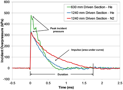
Figure 4. Comparing incident pressure time-histories measured at the end of the shock tube for three different shock tube configurations with the same burst pressure (4200 kPa).
Diaphragm burst pressure increased linearly with diaphragm thickness (R2 > 0.96) and was independent of driver gas or stock tube length. Burst pressure, driven section length, and driver gas were all significant factors affecting peak overpressure (all p < 0.001, R2 = 0.92). Similarly, driver gas type, driven section length, and burst pressure were significant factors for blast duration (all p < 0.001, R2 = 0.83).
The effect of these shock tube design parameters created six distinct characteristic lines defined by the relationship between peak pressure and duration generated with the shock tube (Figure 5). Increasing the driven length produced blasts that were longer in duration but lower in peak overpressure. The use of compressed nitrogen as the driver gas produced overpressure durations (and impulses) much longer than durations produced with compressed helium at the same burst pressure. For shock tube blasts using the 630-mm shock tube at burst pressures greater than 3000 kPa, the measured overpressure duration did not increase like the other tubes, appearing to saturate around 0.73 ms. This difference may indicate that the driven-to-driver length ratio in the 630-mm design was not sufficiently long enough to fully develop Friedlander-like blast profiles at higher burst pressures.
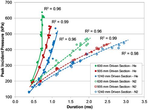
Figure 5. Pressure–duration curves for the different shock tubes and driver gas, demonstrating a wide range of short-duration blast overpressures.
Peak incident pressures measured across the diagonal of the end of the shock tube suggested the shock wave was well formed and planar by the time it reached the end of the tube (Figure 6). Pressures across the diagonal were typically within 5% of the averaged wall pressure, and in only two tests were these pressures significantly different from the wall pressures (p < 0.05 for significance). Inter-test variability of peak pressure measured between the three PTs was very low for most of the shock tube configurations and test conditions (Figure 7). On average, the relative error of the peak overpressure measured using all three PTs in the 935 and 1240 mm shock tube was within 5% of the mean, and this variability was improved with increased shock tube length. The inter-test variability of the 630 mm shock tube was significantly higher than for the 935 and 1240 mm tubes (p < 0.05) at nearly 8% relative error. This difference was likely an effect of the shock wave not being completely planar at the end of the shorter shock tube.
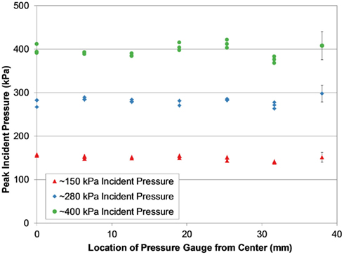
Figure 6. Peak incident pressure measurements across the diagonal of the shock tube (1240 mm helium-driven tube shown), showing consistent pressure levels characteristic of a planar shock wave at the end of the tube.
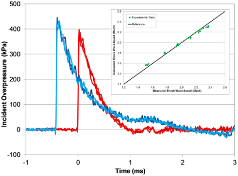
Figure 7. Typical open-tube pressure time-histories measured with three PTs at the end of the tube (red) and 305 mm upwind (blue; 1240 mm helium-driven tube, 5000 kPa burst). Measured shock wave speed matches theoretical speeds for a fully developed shock wave (inset).
The calculated shock wave speed (Eq. 1) was based on 1D shock tube theory (Anderson, 2003), and was calculated using the averaged peak incident overpressure measured by the upwind and end-tube PTs. The measured shock wave speed increased with blast pressure, and was very close to the theoretical shock wave speed based on the averaged shock overpressure (Figure 7). At the lowest burst pressures, the measured shock speed was 3% less than the calculated wave speed, and at the highest burst pressure the measured shock speed was 3% greater.

In vitro Receiver Characteristics
Pressure pulses measured in the fluid-filled receiver at the location of the test sample were characteristic of a fast-rising single acoustic pressure pulse with durations approximately 1.0 ms for all tested conditions (Figure 8). Initial rise-times of the receiver pressure were between 0.15 and 0.20 ms, and were longer than the rise-times of the air shock (approximately 10–20 μs). The decrease in rise-time in the receiver was from the frequency conversion from shock to acoustic loading typically found in wave transmission from low to high speed of sound materials, such as in free-field blast where waves are transmitted from the air to the head (Clemedson and Pettersson, 1956). For the pressure levels tested, the shock impedance of air was approximately three orders of magnitude less than the acoustic impedance of water, and the shock wave/particle velocity of the impinging wave were also less than the speed of sound of water. Thus, the air reflects off the water as a shock, but the transmitted wave into the water was acoustic (cf. Henderson et al., 1990).
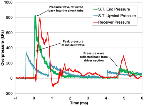
Figure 8. Typical pressure time-histories measured during a shock tube test with the fluid-filled receiver (3800 kPa burst).
Transient low-amplitude pulses follow the initial overpressure pulse, and were likely caused the vibrational modes in the compliant receiver structure. A secondary pressure pulse approximately 5 ms after the initial pulse was caused by the return of the reflected shock wave in the shock tube, and was substantially lower in amplitude than the initial pulse. The transient response of the pressure pulse was highly reproducible among tests with similar blast conditions (Figure 9).
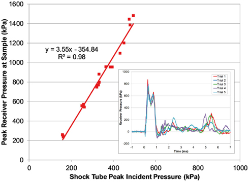
Figure 9. Comparing peak pressure measured in the receiver with the peak incident pressure of the applied blast wave. The transient pressure pulse in the receiver was very reproducible (inset; 3800 burst).
The magnitude of the receiver pressure correlated with the peak incident pressure of the applied blast wave (Figure 9). Peak receiver pressure was greater than the peak incident pressure measured at the end of the tube because the acting pressure on the top surface of the receiver column was a reflected pressure of the shock tube blast, not the unimpinged incident pressure. In the ideal case, there is a direct relationship between the incident and reflected shock pressure (Eq. 2), where shock waves will reflect with pressure amplitudes two to eight times greater than the incident pressure in air (Anderson, 2003).

The increase in pressure at the end of the shock tube from the wave reflection off the receiver was pronounced in the pressure traces (Figure 8). The peak pressure from the initial incident shock wave was distinguishable from the larger reflected wave coming off the receiver. The peak pressure caused by the reflecting wave was 1.5–3 times higher than the incident pressure (this ratio increased with blast severity). It should be noted that the reflecting wave measured with the incident PTs in the shock tube was not the ideal reflected pressure calculated by Eq. 2 since gas could escape through the gaps between the shock tube and receiver. The reflecting pressure was highly sensitive to the positioning between the receiver and the shock tube. Therefore, the response of the receiver to the loading conditions was best characterized by the unimpinged incident pressure wave. Conversely, the ratio between the peak receiver pressure and the ideal reflected pressure (calculated using Eq. 2) was reasonably consistent for all levels tested (0.60 ± 0.06). This ratio was less than 1 as expected, since the interface was not perfectly rigid or closed (gaps lead to escaping gases) and the receiver column was compliant.
Finite Element Model
The open shock tube FE model produced responses that were excellent predictions of the experimental results (Figure 10), and over 90% of the model pressure time-history data for all blast levels simulated fit within the experimental corridors. Shock wave speeds in the FE models were nearly identical to the theoretical shock wave velocities shown in Figure 7. The agreement between the FE model with the experimental data was not surprising given that LS-DYNA accurately reproduces theoretical shock tube flow when using a sufficiently refined FE mesh (Panzer et al., 2011).
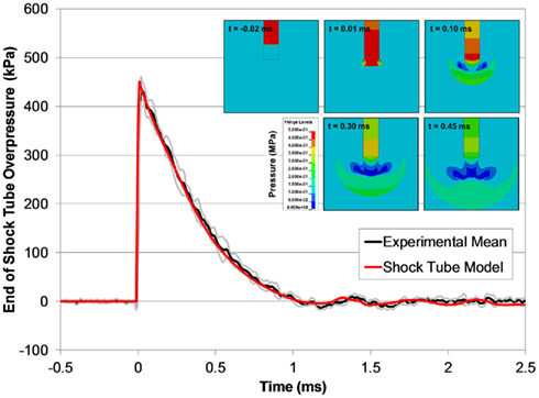
Figure 10. A comparison between typical the pressure time-histories of the FE shock tube model and the experimental pressure traces at the same blast condition (6200 kPa burst). Pressure contours show the time-lapsed progression of the blast wave at the end of the tube (inset).
The receiver model also predicted the experimental response of the receiver, but was slightly longer in duration of the initial pressure pulse (Figure 11). The model was able to capture the fundamental design response of the receiver, namely the propagation of the pressure pulse down the test column through the sample and the attenuation and dispersion of the pressure through the diverging nozzle. The pressure wave reflected back into the shock tube in the model was also an excellent fit with the experimental data, validating the fluid–structure interaction between the blast model and the receiver model.
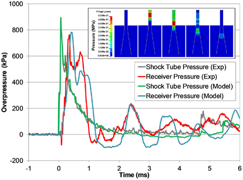
Figure 11. A comparison between typical the pressure time-histories of the FE shock tube and receiver model and the experimental pressure traces at the same blast condition (3700 kPa burst). Pressure contours show the time-lapsed progression of the pressure pulse traveling down the test column and dispersing into the reservoir (inset).
For all blast conditions simulated, the pressure responses measured at the depth of the sample location were uniform across the diameter (±4% variation from the mean) up to 3 mm from the test column wall, where peak pressure was typically 15% lower than in the center. The receiver simulations also predicted bulk fluid motion through the test column, noticeable by up to 8.5 mm of displacement at the top surface of the test column in the most severe case. This bulk motion was confirmed experimentally via high-speed video.
We investigated the potential for tissue culture strain using this system by simulating a surrogate injury model in the FE receiver model. For all blast levels simulated, the maximum principal strain in the tissue did not exceed 5% and all measured strain rates were less than 80 s−1. Maximum tissue strains did not develop during the initial pressure pulse, but did develop later in the test when the motion of the well within the test column caused the tissue to stretch (Figure 12).
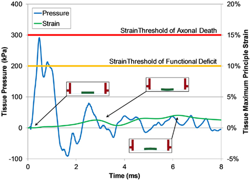
Figure 12. Typical pressure and maximum principle strain traces of tissue calculated by the FE shock tube and receiver model (1300 kPa burst). Predicted strain levels were much lower than the low strain-rate thresholds for function deficiency and axonal death (Bain and Meaney, 2000; Morrison III et al., 2003).
Discussion
In vivo Injury Models
A substantial amount of blast-related neurotrauma research has focused on understanding the mechanisms and effects caused by direct impingement of the blast wave on the body (known as a primary blast injury). In vivo animal models are used to elucidate the pathological effects of BINT, with the most common species being small rodents (mice or rat). Previous studies have reported a wide array of histological and gross pathological perturbations following blast exposure to in vivo models. Structural and/or morphological changes have been reported using a variety of histochemical and microscopy techniques in neuronal and glial cells following blast exposure (Kaur et al., 1995; Cernak et al., 2001; Moochhala et al., 2004; Long et al., 2009; Garman et al., 2011; Pun et al., 2011). Blood–brain barrier defects were found post-blast resulting in increased permeability (Garman et al., 2011; Risling et al., 2011). In more severe BINT, gross pathological findings were typically present as mild or moderate subarachnoid and/or subdural hemorrhaging (Kaur et al., 1995; Bauman et al., 1997; Säljö et al., 2008; Long et al., 2009; Cheng et al., 2010; Rafaels et al., 2011). More recently, the clinical manifestation of apnea immediately following blast exposure were reported in many animal models exposed to blast waves (Long et al., 2009; Cheng et al., 2010; Garman et al., 2011; Rafaels et al., 2011).
Test methodologies and analyses are not thoroughly established however, and it is difficult to compare results across studies because of the vast differences in methods and resulting blast exposures. One major limitation to current in vivo BINT models is the unknown scaling between the animal model and the human response (Bass et al., 2012). A vital component in establishing a human blast injury criterion is the methodology of scaling the characteristics of a blast (pressure, duration, impulse) associated with an animal injury to the equivalent blast exposure for a human. The scaling law widely used for pulmonary blast injury models scales the blast overpressure duration by the cube root of the ratio between body masses of species (Bowen et al., 1968). This simplified dimensional procedure only considers the scaling of the duration (and impulse) of the blast overpressure and not its amplitude. Remarkably, the scaling law developed for pulmonary blast injuries is identical to those developed independently for automotive blunt impacts (Eppinger and Marcus, 1984) despite the vast differences in the total momentum in each loading type. Injurious short-duration blasts generally have lower total momentum.
Establishment of a definitive scaling law for BINT has been hampered by the lack of test data across a wide range of species and blast conditions (Bass et al., 2012). In studies that report blast durations (an important parameter for blast loading), most small rodent models have been exposed to overpressure durations greater than 4 ms (e.g., Chavko et al., 2007; Svetlov et al., 2010; Säljö et al., 2010; Bolander et al., 2011; Garman et al., 2011; Leonardi et al., 2011), and some greater than 10 ms (e.g., Cernak et al., 2001; Pun et al., 2011). Further, the applied overpressure time-histories often have impulse values that are far larger than a typical ideal free-field overpressure wave and are different in character than typical complex blast waves (Bass et al., 2012).
If the scaling laws for BINT were based on the cubed-root of the mass ratio (as in pulmonary blast), the corresponding scaled blast duration for a human (70 kg) would be over 6 times that of a rat (300 g) and over 13 times that of a mouse (30 g). For example, a mouse exposed to a 200 kPa peak incident overpressure blast with a duration of 5 ms would be equivalent to a human exposed to 200 kPa peak incident pressure and 65 ms duration, a surface blast produced by the detonation of a 27,000- kg charge of TNT from 70 m away (Hyde, 2004). Long duration blast tests producing TBI in small animal models may simulate TBI in humans exposed to extremely large conventional high explosives or nuclear blasts, but not the real-world blast threat from typical IEDs. Therefore, short-duration blasts (particularly in small animal models) may more accurately represent the exposures seen in BINT victims. More research is required with these short-duration test conditions, and using the shock tubes described in this manuscript will achieve these types of loading conditions for in vivo injury models.
Shock Tube Design
A gas driven shock tube is the most common device used to generate blast overpressure conditions for neurotrauma research (e.g., Celander et al., 1955; Cernak et al., 2001; Chavko et al., 2007; Rafaels et al., 2011) because of its ability to produce repeatable blast waveforms that closely resemble free-field blast waves in a controlled laboratory environment. As previously mentioned, most methodologies expose small rodent models to blast overpressures with long durations (>4 ms). Considering this, we designed a set of shock tubes for generating short positive-phase durations (0.3–3 ms) but relatively high peak incident overpressures (up to 650 kPa) for direct exposure to in vivo rodent injury models. The capabilities of the designed shock tube allow for scaled equivalent human durations to range from 1.8 to 18 ms for a rat injury model and 3.9 to 39 ms for a mouse injury model, which are more representative of real-world conditions than long duration shock tube tests. However, if BINT scaling laws are different from pulmonary injury scaling, then the designed shock tube fills a gap in the range of blast conditions tested with current methodologies.
A number of factors are important for designing a shock tube to produce the blast characteristics desired, the most critical being driver gas type, diaphragm burst pressure, and the ratio between driven length and driver length (Bass et al., 2012). For the current shock tube design, the diameter also needed to be large enough to expose a rodent head to a well-defined plane wave, but small enough for bench-top application. The rule-of-thumb for shock tube design is to use a driven length to diameter ratio greater than 10 to ensure the shock wave is planar (cf. Bass et al., 2012), and in the case of the 630 mm design, this ratio is approximately 8. This likely explains the significant increase in inter-test variability with the 630 mm tube.
One of the issues we have experienced with using the shock tube was the batch-to-batch variability of the PET membranes (both thickness and failure stress). For instance, a 1.27-mm diaphragm (5 × 0.254 mm sheets) test condition averaged burst pressures of 4887 kPa (±62 kPa SD) for one batch of film and 6005 kPa (±27 kPa SD) for another using the same test conditions. The thickness of a batch of PET film has a variability of ±10% (personal communication; Grafix Plastics Inc., Cleveland, OH, USA), and this variability can compound when multiple membranes are used to build the diaphragm. While this issue did not affect the response of the shock tube (peak pressure and duration were well correlated with burst pressure), but it did affect our ability to precisely control the blast conditions during a large test series when different batches of PET may be used. We are currently implementing quality assurance protocols to assess individual diaphragm batches and improve this precision.
In vitro Injury Models
In vitro models are an important tool for elucidating the pathobiology of TBI caused by mechanical disruption of central nervous system (CNS) tissue by allowing researchers to reduce the complexity of in vivo TBI models and improve access to the biological and mechanical parameters associated with the tissue. However, for in vitro models to be effective in improving our understanding of the injury sequelae, they must accurately represent the in vivo post-injury response to mechanical loading. Morrison III et al. (2011) provides a comprehensive review on in vitro models for TBI and their recapitulation of in vivo pathobiology.
A large number of in vitro TBI models were developed for understanding the response of CNS tissue to mechanisms caused by blunt head impact or inertial loading. Many of these models focused on applying a disruption to the CNS tissue in shear (e.g., LaPlaca and Thibault, 1997; LaPlaca et al., 2005) or in stretch (e.g., Cargill and Thibault, 1996; Morrison III et al., 1998, 2003, 2006). The fastest deformation capabilities of these in vitro models can apply strains to tissue at rates up to 50 s−1(Morrison III et al., 2003; Cater et al., 2006). However, these rates are too slow for replicating conditions caused by blast loading, where strains are typically very low (less than 10%) but strain rates may be very high (100–1000 s−1; Panzer et al., 2012b). Thus, new in vitro injury models are needed to study the pathobiological effects of TBI caused by blast exposure.
Recently, in vitro BINT models were developed for blast loading. Arun et al. (2011) studied the effects of blast overpressure on two types of neuroblastoma cells and found significant neurobiological effects (Arun et al., 2011). They also report the counter-intuitive result that repeated exposure from consecutive blasts decreased injury. Their methodology consisted of exposing a 96 well plate of cell cultures sealed with a gas permeable membrane to air-driven shock tube blasts of 94, 125, and 145 kPa peak incident overpressure (overpressure duration not provided), although actual pressures exposed to the cell cultures inside the blasted plate were not reported. Connell et al. (2011) developed an in vitro model of the isolated guinea pig spinal cord exposed to blast overpressures and found a reduction in the conduction of action potentials and a decrease in membrane integrity (Connell et al., 2011). Their test methodology consisted of exposing an isolated spinal cord directly to a jet of gas produced by a blast tube with overpressure levels of 23, 41, and 65 kPa peak incident pressure (0.2 ms duration for all blasts). Using this methodology, they reported tissue deformation as high as 60% compressive strain. Injuries derived from this in vitro model were likely a result of the tissue being crushed rather than a blast injury.
In vitro Receiver Design
A fluid-filled receiver was designed to replicate the in vivo boundary conditions for in vitro cellular and organotypic tissue samples subjected to an overpressure pulse caused by a blast wave. The initial geometry specifications were based on the receiver working with the 78 mm diameter shock tube and incorporating existing in vitro neurotrauma models. The initial performance specification for the receiver was to achieve a range of single overpressure pulses between 0.5 and 2 ms in duration, similar to those seen with early cadaveric blast testing (Rafaels et al., 2010) and computational studies (Panzer et al., 2012b). The use of in silico prototyping using FE models helped design the final geometry and determine the materials for building the apparatus. In-fluid membrane materials were selected based on similar acoustic impedance with water to reduce reflections and ensure smooth transmission of the pressure pulse through the culture. Lastly, the receiver was designed to be modifiable for future studies to produce more complex waveforms simulating blast overpressures in operational environments. Compliance of the receiver structure plays an important role in the characteristics of the pressure pulse at the culture, and altering the structure can tune the receiver to desired pressure responses.
This in vitro test methodology was the first to replicate the loading conditions and boundary conditions that are relevant for studying BINT by not compressing the injury model against a material with higher impedance. This methodology allows for the direct measurement of the overpressure applied to the specimen during the test, and this capability will allow for the future development of injury criteria that can be applied to computational models for injury risk assessment.
The rationale for this design was to surround the sample with materials with similar bulk properties and impedance so that the applied pressure wave propagated through the tissue rather than reflected off the tissue. This was an important aspect of the methodology because reflecting the applied wave off the sample will have the unintended consequence of large tissue deformations not associated with blast. Furthermore, the receiver was designed to mitigate and attenuate possible pressure wave reflections that may return to the tissue in an effort to reduce the possibility of additional tissue disruption from repeated loading. Repeated loading can increase the risk of injury in a blast environment (Panzer et al., 2012a), so it is desirable to identify an injury tolerance based on a single loading instance.
Bulk fluid motion was produced in the test column following the application of the blast wave. However, bulk fluid motion was not detrimental to maintaining low strain amplitudes in the test sample since the sample was moving with the fluid. Tissue strains were less than 5% for the conditions simulated, which is a level of tissue strain well below the thresholds for functional deficiency in CNS tissue (Bain and Meaney, 2000; Morrison III et al., 2003; Cater et al., 2006; Elkin and Morrison III, 2007). This result gives confidence that injuries modeled using this methodology are from overpressure loading and not strain loading.
One of the advantages of the fluid-filled receiver is that it is not limited to a specific in vitro culture model. Many types of tissues, including organotypic slices and cell cultures, are being tested using this methodology for in vitro blast injury modeling. Furthermore, the dimensions of the receiver can be modified in the future to tailor the applied overpressure pulse to match specific intracranial pressure traces seen in animal or cadaveric blast models. This may be particularly important when considering more complex intracranial pressure pulses caused by the interaction of the blast with the head and its surroundings (including helmets and other protective equipment).
Conflict of Interest Statement
The authors declare that the research was conducted in the absence of any commercial or financial relationships that could be construed as a potential conflict of interest.
Acknowledgments
The authors gratefully acknowledge funding support from the Army Research Office under the Multidisciplinary University Research Initiative (W911MF-10-1-0526; University of Pennsylvania as prime institution).
References
Anderson, J. D. (2003). Modern Compressible Flow: With Historical Perspective. New York, NY: McGraw-Hill.
Arun, P., Spadaro, J., John, J., Gharavi, R. B., Bentley, T. B., and Nambiar, M. P. (2011). Studies on blast traumatic brain injury using in-vitro model with shock tube. Neuroreport 22, 379–384.
Bain, A. C., and Meaney, D. F. (2000). Tissue-level thresholds for axonal damage in an experimental model of central nervous system white matter injury. J. Biomech. Eng. 122, 615.
Bass, C. R., Panzer, M. B., Rafaels, K. A., Wood, G. W., and Capehart, B. P. (2012). Brain injuries from blast. Ann. Biomed. Eng. 40, 185–202.
Bauman, R. A., Elsayed, N. M., Petras, J. M., and Widholm, J. (1997). Exposure to sublethal blast overpressure reduces the food intake and exercise performance of rats. Toxicology 121, 65–79.
Bolander, R., Mathie, B., Bir, C., Ritzel, D., and Vandevord, P. (2011). Skull flexure as a contributing factor in the mechanism of injury in the rat when exposed to a shock wave. Ann. Biomed. Eng. 39, 2550–2559.
Bowen, I. G., Fletcher, E. R., and Richmond, D. R. (1968). Estimate of man’s tolerance to the direct effects of air blast. Albuquerque, NM: Lovelace Foundation for Medical Education and Research.
Boyd, R., Royles, R., and El Deeb, K. M. M. (2000). “Simulation and validation of UNDEX phenomena relating to axisymmetric structures,” in 6th International LS-DYNA Users Conference (Detroit, MI: Int LS-DYNA C).
Cargill, R. S., and Thibault, L. E. (1996). Acute alterations in [Ca2+] i in NG108-15 cells subjected to high strain rate deformation and chemical hypoxia: an in vitro model for neural trauma. J. Neurotrauma 13, 395–407.
Cater, H. L., Sundstrom, L. E., and Morrison, B. III. (2006). Temporal development of hippocampal cell death is dependent on tissue strain but not strain rate. J. Biomech. 39, 2810–2818.
Celander, H., Clemedson, C. J., Ericsonn, U. A., and Hultman, H. I. (1955). The use of a compressed air operated shock tube for physiological blast research. Acta Physiol. Scand. 33, 6–13.
Cernak, I., Wang, Z., Jiang, J., Bian, X., and Savic, J. (2001). Ultrastructural and functional characteristics of blast injury-induced neurotrauma. J. Trauma 50, 695–706.
Chavko, M., Koller, W. A., Prusaczyk, W. K., and Mccarron, R. M. (2007). Measurement of blast wave by a miniature fiber optic pressure transducer in the rat brain. J. Neurosci. Methods 159, 277–281.
Cheng, J., Gu, J., Ma, Y., Yang, T., Kuang, Y., Li, B., and Kang, J. (2010). Development of a rat model for studying blast-induced traumatic brain injury. J. Neurol. Sci. 294, 23–28.
Clemedson, C. J., and Pettersson, H. (1956). Propagation of a high explosive air shock wave through different parts of an animal body. Am. J. Physiol. 184, 119–126.
Connell, S., Gao, J., Chen, J., and Shi, R. (2011). Novel model to investigate blast injury in the central nervous system. J. Neurotrauma 28, 1229–1236.
Effgen, G. B., Hue, C. D., Vogel, E. III, Panzer, M. B., Meaney, D. F., Bass, C. R., and Morrison, B. III. (2012). A multiscale approach to blast neurotrauma modeling: part II: methodology for inducing blast injury to in vitro models. Front. Neurol. 3:23. doi:10.3389/fneur.2012.00023
Elkin, B. S., and Morrison, B. III. (2007). Region-specific tolerance criteria for the living brain. Stapp Car Crash J. 51, 127–138.
Eppinger, R. H., and Marcus, J. H. (1984). “Development of dummy and injury index for NHTSA’s thoracic side impact protection research program,” in SAE Government/Industry Meeting and Exposition (Washington, DC: Society of Automotive Engineers).
Garman, R. H., Jenkins, L. W., Switzer, I. R. C., Bauman, R. A., Tong, L. C., Swauger, P. V., Parks, S., Ritzel, D. V., Dixon, C. E., Clark, R., Bayir, H., Kagan, V., Jackson, E. K., and Kochanek, P. M. (2011). Blast exposure in rats with body shielding is characterized by diffuse axonal injury. J. Neurotrauma 28, 947–959.
Hallquist, J. O. (2007). LS-DYNA Keyword User’s Manual. Livermore, CA: Livermore Software Technology Corporation.
Henderson, L., Jia-Huan, M., Akira, S., and Kazuyoshi, T. (1990). Refraction of a shock wave at an air – water interface. Fluid Dyn. Res. 5, 337–350.
Hyde, D. W. (2004). CONWEP 2.1.0.8, Conventional Weapons Effects Program. Vicksburg, MS: United States Army Corps of Engineers.
Kaur, C., Singh, J., Lim, M., Ng, B., Yap, E. P., and Ling, E. A. (1995). The response of neurons and microglia to blast injury in the rat brain. Neuropathol. Appl. Neurobiol. 21, 369–377.
LaPlaca, M. C., Cullen, D. K., Mcloughlin, J. J., and Cargill, R. S. (2005). High rate shear strain of three-dimensional neural cell cultures: a new in vitro traumatic brain injury model. J. Biomech. 38, 1093–1105.
LaPlaca, M. C., and Thibault, L. E. (1997). An in vitro traumatic injury model to examine the response of neurons to a hydrodynamically-induced deformation. Ann. Biomed. Eng. 25, 665–677.
Leonardi, A. D. C., Bir, C. A., Ritzel, D. V., and Vandevord, P. J. (2011). Intracranial pressure increases during exposure to a shock wave. J. Neurotrauma 28, 85–94.
Long, J. B., Bentley, T. L., Wessner, K. A., Cerone, C., Sweeney, S., and Bauman, R. A. (2009). Blast overpressure in rats: recreating a battlefield injury in the laboratory. J. Neurotrauma 26, 1–14.
Moochhala, S. M., Md, S., Lu, J., Teng, C. H., and Greengrass, C. (2004). Neuroprotective role of aminoguanidine in behavioral changes after blast injury. J. Trauma. 56, 393–403.
Morrison, B. III, Cater, H. L., Benham, C. D., and Sundstrom, L. E. (2006). An in vitro model of traumatic brain injury utilising two-dimensional stretch of organotypic hippocampal slice cultures. J. Neurosci. Methods 150, 192–201.
Morrison, B. III, Cater, H. L., Wang, C. C. B., Thomas, F. C., Hung, C. T., Ateshian, G. A., and Sundstrom, L. E. (2003). A tissue level tolerance criterion for living brain developed with an in vitro model of traumatic mechanical loading. Stapp Car Crash J. 47, 93–105.
Morrison, B. III, Meaney, D. F., and Mcintosh, T. K. (1998). Mechanical characterization of an in vitro device designed to quantitatively injure living brain tissue. Ann. Biomed. Eng. 26, 381–390.
Morrison, B. III, Elkin, B. S., Dolle, J.-P., and Yarmush, M. L. (2011). In vitro models for traumatic brain injury. Annu. Rev. Biomed. Eng. 13, 91–126.
Nelson, T. J., Clark, T., Stedje-Larsen, E. T., Lewis, C. T., Grueskin, J. M., Echols, E. L., Wall, D. B., Felger, E. A., and Bohman, H. R. (2008). Close proximity blast injury patterns from improvised explosive devices in Iraq: a report of 18 cases. J. Trauma 65, 212–217.
Nicolle, S., Lounis, M., Willinger, R., and Palierne, J.-F. (2005). Shear linear behavior of brain tissue over a large frequency range. Biorheology 42, 209–223.
Owens, B. D., Kragh, J. F. Jr., Wenke, J. C., Macaitis, J., Wade, C. E., and Holcomb, J. B. (2008). Combat wounds in operation Iraqi freedom and operation enduring freedom. J. Trauma 64, 295–299.
Panzer, M. B., Bass, C. R., Rafaels, K. A., Shridharani, J., and Capehart, B. P. (2012a). Primary blast survival and injury risk assessment for repeated blast exposures. J. Trauma 72, 454–466.
Panzer, M. B., Myers, B. S., and Bass, C. R. (2011). Mesh considerations for finite element blast modeling in biomechanics. Comput. Methods Biomech. Biomed. Eng. doi:10.1080/10255842.2011.629615
Panzer, M. B., Myers, B. S., Capehart, B. P., and Bass, C. R. (2012b). Development of a finite element model for blast brain injury and the effects of CSF cavitation. Ann. Biomed. Eng. doi: 10.1007/s10439-012-0519-2
Pun, P. B. L., Kan, E. M., Salim, A., Li, Z., Ng, K. C., Moochhala, S. M., Ling, E. A., Tan, M. H., and Lu, J. (2011). Low level primary blast injury in rodent brain. Front. Neurol. 2:19. doi:10.3389/fneur.2011.00019
Rafaels, K. A., Bass, C. R., Salzar, R. S., Panzer, M. B., Woods, W., Feldman, S., Cummings, T., and Capehart, B. (2011). Survival risk assessment for primary blast exposures to the head. J. Neurotrauma 28, 2319–2328.
Rafaels, K. A., Shridharani, J. K., Bass, C. R., Salzar, R. S., Walilko, T. J., Wood, G. W., and Panzer, M. B. (2010). “Blast wave attenuation: ballistic protective helmets and the head,” in Personal Armour Systems Symposium (Quebec City, QC: PASS).
Risling, M., Plantman, S., Angeria, M., Rostami, E., Bellander, B. M., Kirkegaard, M., Arborelius, U., and Davidsson, J. (2011). Mechanisms of blast induced brain injuries, experimental studies in rats. Neuroimage 54, S89–S97.
Säljö, A., Arrhén, F., Bolouri, H., Mayorga, M., and Hamberger, A. (2008). Neuropathology and pressure in the pig brain resulting from low-impulse noise exposure. J. Neurotrauma 25, 1397–1406.
Säljö, A., Bolouri, H., Mayorga, M., Svensson, B., and Hamberger, A. (2010). Low-level blast raises intracranial pressure and impairs cognitive function in rats: prophylaxis with processed cereal feed. J. Neurotrauma 27, 383–389.
Schneiderman, A. I., Braver, E. R., and Kang, H. K. (2008). Understanding sequelae of injury mechanisms and mild traumatic brain injury incurred during the conflicts in Iraq and Afghanistan: persistent postconcussive symptoms and posttraumatic stress disorder. Am. J. Epidemiol. 167, 1446–1452.
Svetlov, S. I., Prima, V., Kirk, D. R., Gutierrez, H., Curley, K. C., Hayes, R. L., and Wang, K. K. W. (2010). Morphologic and biochemical characterization of brain injury in a model of controlled blast overpressure exposure. J. Trauma 69, 795–804.
Terrio, H., Brenner, L. A., Ivins, B. J., Cho, J. M., Helmick, K., Schwab, K., Scally, K., Bretthauer, R., and Warden, D. L. (2009). Traumatic brain injury screening: preliminary findings in a US Army Brigade Combat Team. J. Head Trauma Rehabil. 24, 14–23.
Keywords: blast injury, shock tube, traumatic brain injury, in vivo model, in vitro model
Citation: Panzer MB, Matthews KA, Yu AW, Morrison III B, Meaney DF and Bass CR (2012) A multiscale approach to blast neurotrauma modeling: part I – development of novel test devices for in vivo and in vitro blast injury models. Front. Neur. 3:46. doi: 10.3389/fneur.2012.00046
Received: 02 November 2011; Accepted: 09 March 2012;
Published online: 28 March 2012.
Edited by:
Ibolja Cernak, University of Alberta, CanadaReviewed by:
Namas Chandra, University of Nebraska–Lincoln, USATim Harrigan, Johns Hopkins University Applied Physics Laboratory, USA
Copyright: © 2012 Panzer, Matthews, Yu, Morrison III, Meaney and Bass. This is an open-access article distributed under the terms of the Creative Commons Attribution Non Commercial License, which permits non-commercial use, distribution, and reproduction in other forums, provided the original authors and source are credited.
*Correspondence: Matthew B. Panzer and Cameron R. Bass, Department of Biomedical Engineering, Duke University, 136 Hudson Hall, PO Box 90821, Durham, NC 27708, USA. e-mail: matthew.panzer@duke.edu; dale.bass@duke.edu