
- 1 Network Biology Research Laboratories, Technion – Israel Institute of Technology, Haifa, Israel
- 2 Department of Cognitive Neurology, Hertie-Institute for Clinical Brain Research, University of Tübingen, Tübingen, Germany
- 3 Pediatrics Department A, Meyer Children’s Hospital, Rambam Medical Center, Haifa, Israel
Distinct modules of the neural circuitry interact with each other and (through the motor-sensory loop) with the environment, forming a complex dynamic system. Neuro-prosthetic devices seeking to modulate or restore CNS function need to interact with the information flow at the level of neural modules electrically, bi-directionally and in real-time. A set of freely available generic tools is presented that allow computationally demanding multi-channel short-latency bi-directional interactions to be realized in in vivo and in vitro preparations using standard PC data acquisition and processing hardware and software (Mathworks Matlab and Simulink). A commercially available 60-channel extracellular multi-electrode recording and stimulation set-up connected to an ex vivo developing cortical neuronal culture is used as a model system to validate the method. We demonstrate how complex high-bandwidth (>10 MBit/s) neural recording data can be analyzed in real-time while simultaneously generating specific complex electrical stimulation feedback with deterministically timed responses at sub-millisecond resolution.
Introduction
The experimental method of placing a biological system within a low-latency closed loop control system is well established in the “dynamic clamping” of single nerve cells (Sharp et al., 1993; Robinson, 1994; Prinz et al., 2004). Taking a similar approach to the network level, however, currently requires a highly specialized software and hardware set-up to achieve a feedback system with sufficiently deterministic latencies and narrow response-time windows for realistic motor-sensory loops (Rutten, 2002; Wolpawa et al., 2002; Ahissar and Kleinfeld, 2003; Karniel et al., 2005; Novellino et al., 2007). This constitutes both a significant investment in terms of time and cost, but also limits the scope of the methods in being applicable only for the specific set of experiments they were designed for. In recent years, however, the increasing computational power in low-cost desktop computers has made it possible to perform complex calculations on high-bandwidth signals in real-time on a number of versatile standard platforms.
Here, we demonstrate how The MathWorks Matlab and Simulink programming framework can be adapted in a generic way (1) to acquire multi-channel electrophysiological signals from a neuronal experimental preparation, (2) to perform complex data analysis, (3) to control almost any kind of telemetry and sensor system and, (4) to provide contingent multi-channel feedback stimulation with sub-millisecond latency. Our software programs are freely available for download at ModelDB (http://senselab.med.yale.edu/modeldb/ShowModel.asp?model = 128068) and can be adapted to a wide range of closed-loop experimental paradigms. Advanced programming is not required as the real-time stage consists of a high-level visually developed Simulink signal processing model and simple control scripts.
Materials and Methods
Basic Principle
The feedback system consists of two standard desktop computers: (1) The self-contained “target” PC, running a dedicated real-time operating system kernel (Mathworks Real-Time Workshop xPC Target), is connected to all the instruments relevant for experimental measurement and control. Visually programmed signal based Mathworks Simulink models are compiled to run independently on the real-time target PC to acquire data, analyze spike-trains and generate feedback signals at synchronous iteration steps paced by an interrupt at an interval of 50–500 μs (depending on the number of channels, required sampling rate and feedback processing complexity, 10 MBit/s data throughput represents an approximate upper limit). (2) The “host” PC, runs Mathworks Matlab and an asynchronous Simulink interface providing the experimenter with control of parameters, as well as on-line visualization and data archiving. The two parts of the system communicate through a 100-MBit TCP/IP (UDP for data streaming) network connection (see Figure 1).
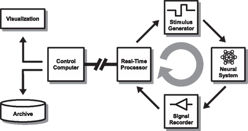
Figure 1. Overall set-up. The set-up consists of a closed-loop real-time stage (right side) that streams relevant data to a controller (“host”) for visualization and archiving (left side). In our model implementation, a 60-channel multi-electrode interface head-stage (Multi Channel Systems MEA1060-BC) is used to interface with a neuronal culture (Neural System). Analog voltage signals are recorded simultaneously from all channels after passing through a filter-amplifier using a multifunction data acquisition card (Signal Recorder) at a sample rate of 16 kHz/channel. A standard PC (Real-Time Processor) is configured to run a Mathworks Simulink Real-Time model paced at 500 μs iteration steps to process and analyze the data. If predefined (dynamic) conditions are met, a feedback stimulus is triggered after a sub-millisecond resolution delay (Stimulus Generator). The stimulation parameters can be modified in response to the ongoing activity using a serial instrument control protocol. The analog “raw voltage” signal, along with other information about the processed data, is streamed via a UDP local area network connection to a host PC running Matlab (Control Computer – “host”) for on-line visualization and archiving. The real-time processor PC and parameters of the feedback model are also controlled through the network from the control computer.
Model Implementation
A multi-channel electrode array (Stett et al., 2003) interface with a primary neuronal culture was chosen as a well-established experimental model system. Such cultured nerve cells exhibit considerable potential for plasticity (Shahaf and Marom, 2001; Eytan et al., 2003; Van Pelt et al., 2005), and information can be transferred to and from the network in a well-defined manner. The model implementation is thus sufficiently complex to demonstrate the capacity of our approach but remains generic enough to serve as a straightforward starting-point for the development of custom in vitro or in vivo applications.
Cortical tissue was taken from newborn rats and plated (after dissociation) on commercially available substrate integrated 60-electrode array dishes (Multi Channel Systems MCS GmbH, electrode diameter: 30 μs, electrode spacing: 200 or 500 μm, material: TiN) using standard procedures described elsewhere (Eytan et al., 2004) and maintained at 37°C in an atmosphere of 5% CO2 and 95% air. Experiments were performed after a 21-day incubation period, during which time a mature densely inter-connected network forms that spontaneously exhibits a characteristic bursting activity pattern (Maeda et al., 1995; Beggs and Plenz, 2003; Eytan and Marom, 2006; Plenz and Thiagarajan, 2007). The dissociated neuronal cultures develop to exhibit a rich repertoire of spontaneous spatio-temporal activity (Wagenaar et al., 2006) that may be classified by various methods, such as an order-based representation (Shahaf et al., 2008). Electrical stimulation at different electrodes, or using different amplitudes and frequencies has distinguishable effects (Marom and Shahaf, 2002).
Action potentials are recorded from the electrode array using a head-stage and a filter-amplifier (Multi Channel Systems MCS GmbH MEA1060-BC and FA60) and acquired by a standard desktop PC (running the Mathworks xPC Target operating system) through a supported data acquisition card (see xPC Target documentation). Every 500 μs, an interrupt service routine is executed to process the acquired “frame” of data (8 × 60 12 bit samples) while the card is continuously acquiring the next frame of data in the background. Action potentials are detected and aligned by a threshold criterion and further processed by the feedback generation system. More complex detection algorithms for either individual events (e.g., spikes) or spatio-temporal composites can be implemented without compromising the performance of the system. A tunable refractory period (2.5 ms) prevents multiple detection of single events that cross the threshold several times.
Feedback Stimulation
Interactive feedback can be provided through a physical telemetry motor and sensor system or directly through an electric stimulus. The analog output of the data acquisition card could be used in principle to synthesize a stimulus waveform (through a stimulus isolator circuit), however, in our example, we use the programmable stimulus generator supplied with the MEA set-up (Multi Channel Systems MCS GmbH STG1002), which is connected to the head-stage at the electrode array. The MEA1060-BC head-stage is programmable, so that a set of any of the 60 recording electrodes can be dynamically selected for stimulation. During stimulation, a TTL trigger and blanking signal lasting 1 ms is applied to the head-stage, electronically switching the designated stimulus electrodes to the stimulus generator lines and all other electrodes to ground. In this way, stimulation artifacts are almost completely suppressed allowing action potentials to be recorded again within 2 ms after stimulation.
The STG1002 stimulus generator and the MEA1060-BC head-stage are two independent instruments, controlled by the real-time model through independent serial RS232 programming lines and triggered by two of the digital output lines of the data acquisition card (Simulink implementation of the programming protocols are included in the example software). All experimental control is thus performed by the real-time target PC, the drivers and control software provided by MCS for Windows are not used. The subset of stimulating electrodes is dynamically selected using a serial command string of 40–60 bytes length (depending on the complexity of the desired waveform). Likewise, the applied waveform is dynamically controlled using a serial command string of 54 bytes length (biphasic symmetric unipolar voltage stimulation, amplitude: 100–900 mV, duration: 200 μs negative pulse, 200 μs positive pulse).
It therefore takes less than 10 ms to transmit the commands for both selecting a new set of stimulating electrodes and changing the stimulus waveform by reprogramming the respective instruments through the two independent serial lines. Integration of the control software within in the real-time model allows a high bandwidth feedback signal to be delivered as a function of the ongoing activity at a rate of up to 100 Hz (the stimulus generator STG1002 is limited to a maximum triggering frequency of 50 Hz). This means that a stimulus of dynamically varying form can be delivered through a variable set of electrodes every 10 ms (this can be improved by using different apparatus and/or firmware if necessary).
The above feedback procedure may be adapted to other modalities, e.g., activity-dependent application of neuromodulators, sound, light, motion, and so forth.
Real-Time Data Processing
The Mathworks Simulink platform provides a wide range of commercially available real-time signal processing and analysis block sets, including adaptive filters, statistical operations, look-up tables and Fourier and wavelet analysis. Complex multidimensional feedback loops can be designed very easily and visually by “dragging and dropping” the appropriate blocks inside the model and connecting them with signal lines. For operations that are not supported out-of-the-box, standard procedural code (Matlab M code or C code) can be embedded inside function blocks.
In this example application, we analyze spontaneous spatio-temporal activity patterns (monitored by a 60-channel electrode array) as they occur. The specific realization described here is aimed at detecting the relative timing of the first-spike of each electrode in relation to the onset of a Network Spike (NS) (Eytan and Marom, 2006; Shahaf et al., 2008). Network spikes are detected by a threshold criterion, and the recruitment order is extracted in real-time from the delays to first spikes. The resulting recruitment order is compared to pre-defined templates for on-line classification, and a corresponding output is generated using relevant actuators or stimulus generators. The Simulink model shown in Figure 2 shows an example for real-time detection of electrode onset order.
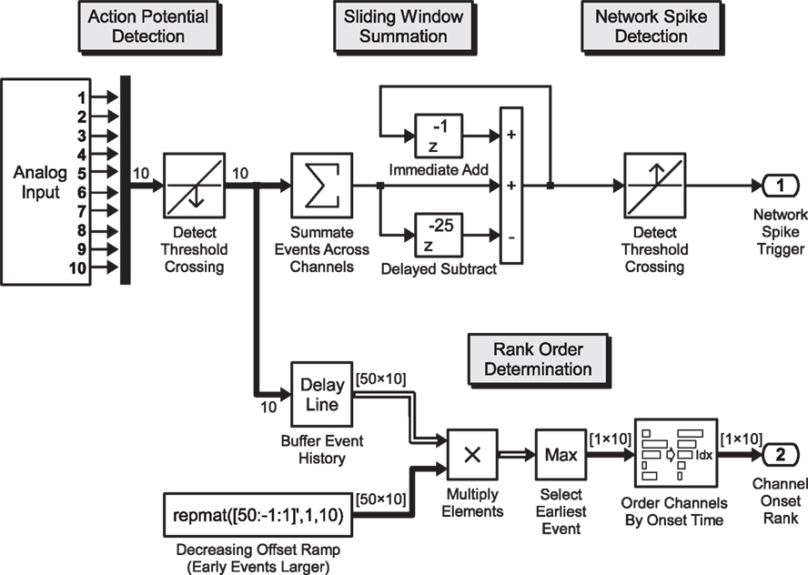
Figure 2. Real-time pattern detection. Exemplary Simulink model for the real-time determination of the onset order of the electrical response across recording channels, during network activity: analog voltage signals from the data acquisition card (10 channels shown) are passed through a threshold detection block which signals a binary “1” on the downward crossing of the negative voltage spike threshold. This 10-element binary vector signal is summed up inside a sliding window of 25 ms and passed again through a threshold detection block that signals the onset of a network spike when a predefined number of spikes have been recorded across all channels in the preceding 25 execution steps (sample model paced at 1 kHz). Within the processing branch shown in the lower section, the spike train is analyzed according to the order of first-spike onset in a window of 50 ms. The 10-element vector is buffered, yielding a 50 × 10 element binary matrix (50 one-millisecond time steps into the past, 10 channels), with the earliest events of each channel (column) on the top rows. This binary matrix is multiplied element-wise with a constant monotonically decreasing “ramp”-matrix with rows yielding a result matrix of which the magnitude of each non-zero element indicates how far in the past the spike occurred. By sorting the largest (time of first spike) value of each column (channel), the index of the sort function yields the order in which the channels became active. A selective feedback stimulus can be generated by comparing the order to a desired order and combining the burst detection signal after a time-delay with the order-match block using a logical AND-gate (not shown).
On-Line Visualization and Control
A limited amount of visualization can be done on the target (Figure 3), but it is the function of the host PC running Matlab to receive and archive the data streams from the real-time system. Spike shapes are extracted from the raw data and stored separately for post-processing. If a feedback signal is generated dynamically on the target, the parameters of the feedback signal (electrode, time, amplitude) are also transmitted and logged as they occur. In this way, the host PC serves as an independent visualization, archiving and post-processing station allowing the experimenter to observe the behavior of the neuronal preparation and state of the feedback system without disturbing its operation.
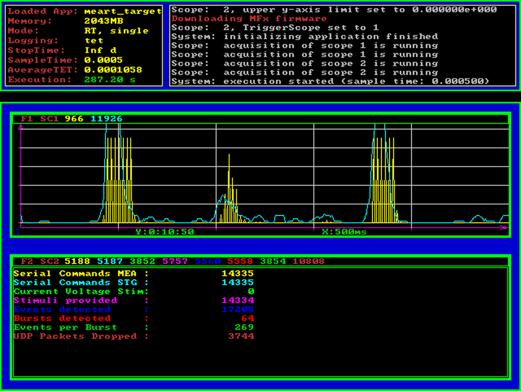
Figure 3. Real-time processor screenshot. The Mathworks xPC Target operating system (loader) provides basic information about the real-time model that is currently being executed using standard VGA graphical output. On the top panel, statistical information and an event log is shown, the area below can be used by the real-time Simulink model to display graphical or numerical target scope data. In this example application, we display the ongoing neural activity summed over a sliding 25 ms window (spikes per bin, cyan curve) as well as the stimulus amplitude and the times of feedback stimulation (yellow curve). The numerical scope at the bottom of the screenshot shows a count of serial commands sent to the head-stage (switching between stimulation electrodes) and the stimulus generator (reprogramming the stimulus waveform) as well as a count of how many stimuli were triggered and how many action potentials and network spikes have been detected up to this point.
The host PC is also used to modify the parameters of the real-time system and to execute different experimental conditions consecutively, making experimental control fully scriptable. The real-time target PC can run continuously for days and weeks interacting with a chronic experimental preparation while the host PC documents relevant aspects of the information flow between preparation and experimental set-up.
Troubleshooting
In what follows, we describe some of our experiences with issues during configuration of this set-up. Note that the real-time model is executed at a fixed rate, which requires a fixed-rate solver to be used for the Simulink model. Each step must execute within the time available, if the step-size is smaller than the maximum task execution time (TET), the model will crash. Power save options and USB controllers in the BIOS should be turned off as they can cause TET spikes. A good approach is to start with a large step size of tens of milliseconds and to reduce it gradually, observing the TET log.
A large number of I/O devices are supported by xPC Target natively (see Mathworks documentation). In our example set-up, we are using the United Electronic Industries PD2-MF-64 for analog data acquisition and for digital output. We have also successfully used National Instruments NI6071E and the Measurement Computing DAS6402 in other versions of this set-up (the AD card supplied by MCS is not supported). In order to synchronize data acquisition with the execution steps of the real-time model, model execution should be paced by an interrupted generated by the data acquisition card to execute the next step when the next batch of samples are available for processing.
If required I/O hardware is not supported natively, it is possible to write custom drivers for this in C code. Likewise, if a desired data processing step is inefficient to implement with Simulink blocks, custom C code can be incorporated inside the model (e.g., for signal processing and spike detection). Note that we don’t use any of the software supplied by MCS, but have implemented all steps of experimental control, data acquisition, processing, archiving, and visualization in a generic and customizable fashion using Matlab/Simulink. It is however possible to run the MCS data acquisition system and software (MCRack) on a separate PC in parallel to the set-up described here through a signal divider (SD-MEA).
Results
Overview
In what follows we demonstrate a number of experimental paradigms that can be realized with the method described. Firstly, we show how spontaneously active multi-channel spike-trains can be monitored while detecting network events in real-time. Raw data in the region of interest before and after the time of threshold crossing are stored for on-line or off-line analysis and categorization. Secondly, we demonstrate how an electric stimulus can be used to interact and interfere with the ongoing activity, both as a “single-shot” and as a modulated stimulus train. These applications were chosen because they are challenging to implement in a generic fashion, and relevant for experimental paradigms aimed at characterization and modulation of complex interactions in neural systems leading to the development of neuro-prosthetic devices.
The spontaneous activity exhibited by a dissociated neuronal culture after 3 weeks in vitro consists of intermittent bursts of activity (“network spikes”) lasting around 100 ms each that are separated by several seconds of relatively sparse activity. As shown in Figure 4 (middle and right panel), the spontaneously occurring multi-channel spike-train patterns of individual network spikes are highly variable and short-lasting, properties that are well suited for demonstrating real-time monitoring and classification capacities.
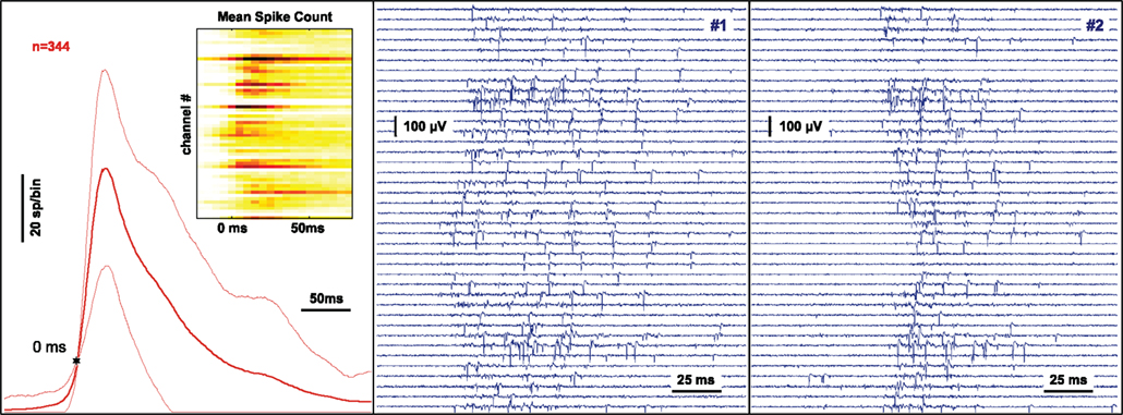
Figure 4. Monitoring and classification of spontaneous neural activity. The signal at 60 substrate-integrated extracellular electrodes recording the neuronal activity from a dissociated nerve cell network after 3 weeks in culture is continuously monitored and analyzed. Network spikes are detected on-line by a threshold criterion. The multi-channel signal is processed online by summing events across all channels inside a sliding window. When a threshold criterion is reached a trigger is generated and the preceding and following complete raw data is stored for analysis. The left panel shows the average of the activity summed across channels using sliding windows of 25 ms duration during a 45 minute recording. The variability is indicated by thin lines at ± 1 SD. The threshold for network spike detection (10 spikes in the past 25 ms) is indicated by the star. The inset shows the probability of a spike being recorded at a particular electrode during the time-course of the network spike using color coding. The center and right panel show the raw voltage traces recorded on 40 channels during two separate network spikes.
The real-time target processes 60-channel data at a rate of 11.5 MBit/s, generates a trigger if a network event is detected and holds the preceding multi-channel data for analysis. During each 500 μs execution step, a sliding window of variable size, containing spike data history, is available for inclusion in online the analysis. It is important to note that the system is capable of interacting with the ongoing neuronal activity at any point during a network spike using the available preceding data (the build-up phase of the activity) to determine the properties of the feedback signal at a response time resolution of 500 μs.
Spike-Train Triggered Interference Stimulation
It is a frequent requirement in biomedicine applications to suppress or otherwise counteract an undesired event, such as synchronized brain activity or re-entrant circular cardiac muscle activity. Here also, a dissociated neuronal culture is used as a model system to demonstrate the efficacy of the method in selectively interfering with neuronal activity using selective electric feedback stimulation.
The feedback generating model consists of two distinct stages: in the first stage, the 60 channel signal is continuously monitored, spikes are detected and summed across channels over a sliding window of 25 ms. Following an earlier study (Eytan and Marom, 2006), network spike onset was determined by using a threshold of 15 channels that are active within that 25 ms time window. A second stage then analyses the spatio-temporal pattern within a variable period of time that begins 50 ms before the threshold crossing, and extends into the time envelope of the network spike as required. If a predefined property of the spike-train is detected (in the example of Figure 5, left panel, the order “1-2-3” was matched) a stimulus is provided at a predefined time in relation to any given temporal reference point (e.g., the network spike threshold crossing or the matching of the spike pattern). This experiment therefore demonstrates the possibility of interfering specifically with a complex activity pattern. The post-stimulus time histogram (Figure 5, right panel, inset) shows one particular channel, in which the feedback stimulus reliably evokes actual spikes. This is thus an example for a short latency closed loop paradigm where a particular activity pattern leads to an interference stimulus which in turn evokes specific activity.
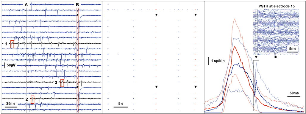
Figure 5. Real-time feedback stimulation contingent upon the spatio-temporal pattern of spikes. The left panel shows raw voltage traces recorded during a network spike. Action potentials are detected by a threshold criterion. When the activity summed across channels in a sliding window of 25ms reaches a threshold (A), the multichannel spike-train is analyzed between the time of −50ms to + 100ms around the point of threshold crossing to determine whether a feedback stimulus should be applied or not. In this example, the feedback criterion is the order (time to first spike) in which channels become active during the burst of activity. A stimulus is provided through two electrodes (triangle) at + 100ms (B) only if the channels become active in the predefined sequence shown (1-2-3). The center panel shows the events recorded on 20 channels over 35 s. The second channel from the top exhibits tonic activity while the other channels fire synchronously during five spontaneous bursts of activity as shown. The third and the fifth burst match the feedback criterion resulting in feedback stimulation as shown (triangle). The right panel shows the average of the activity summed across channels using time-bins of 5 ms during a 2-h recording. Bursts that match the feedback criterion are averaged separately (dashed blue line, n = 142) from those that did not (solid red line, n = 474). The variability is indicated by thin lines at ± 1 SD. The immediate effect of stimulation (triangle) during the matching condition is shown in the inset (events recorded at one channel on 40 separate trials). The probability of a spike occurring is increased at around 12 ms post-stimulus (star).
Continuous Variable Electric Stimulation Feedback to Modulate Ongoing Neural Activity
In this example, we consider the case where both network activity as well as feedback signals are continuous rather than discrete. Network activity is expressed in terms of number of individual action potentials recorded throughout the electrode array within a 25-ms sliding time window. The amplitude of the feedback stimulus was matched to the level of network activity following an arbitrarily pre-defined function. In providing a non-linear delayed feedback signal we implement an algorithm based on the principles described by Popovych et al. (2006): (1) the instantaneous overall activity of the network is estimated by summing events inside a sliding window, (2) an imaginary part is generated for this signal through a Hilbert transform, (3) the result is squared and multiplied with the delayed complex conjugate of the same signal, (4) the real part of the resulting complex signal is taken to determine the feedback amplitude. To approximate a continuous varying feedback signal, a stimulation of variable magnitude between 100 and 900 mV is applied every 20 ms.
Since the Simulink programming environment used in the approach presented here is designed for control systems, it is a trivial matter to implement such mathematical signal processing algorithms efficiently (blocks shown in Figure 6 left panel, bottom) which would ordinarily require many lines of procedural code. In this example, feedback is generated by setting the stimulus amplitude of a programmable stimulus generator in real-time through a serial interface and a TTL pulse trigger line.
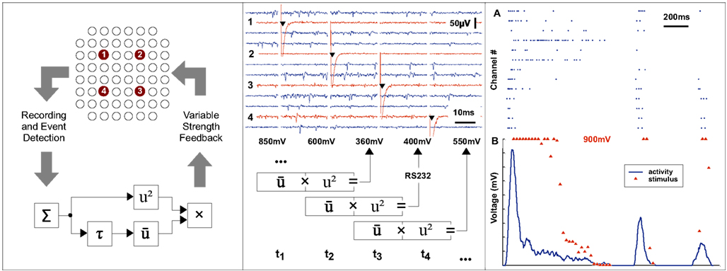
Figure 6. Continuous real-time feedback modulation of neural activity. The left panel shows the principle of a continuous closed loop set-up. The overall activity of a neuronal system is estimated by summing events across recording channels within a sliding window. A non-linear transformation of the input is used as a delayed feedback signal to the neural system. A repetitive stimulation, composed of pulses with variable amplitudes, is applied to each of four predefined electrodes according to a cyclic sequence at a frequency of 40 Hz. The middle panel shows the raw traces recorded at a subset of channels and the stimulus artifacts at the electrodes. The amplitude of the next stimulus is determined from the activity during the current and previous 25 ms time window and the stimulus generator is then reprogrammed accordingly in real-time. The top section of right panel (A) shows events detected at various channels. The corresponding summed activity is shown in the lower section (B, blue line). For each point of time at which a feedback stimulus was delivered, the voltage amplitude is plotted (B, red triangle).
Discussion
The rapid advances in computer technology over the past years have made it feasible to handle a considerable amount of multi-channel long-term recording data. Comprehensive software toolkits are available for the specific task of analyzing large matrices of spike data post hoc using Mathworks Matlab (Egert et al., 2002). Here, we present a framework that complements this approach with the ability to continuously interact with the experimental preparation while at the same time recording all relevant data for subsequent evaluation. Beyond the ease of integration with post-processing and control scripts, we consider the main strengths of our approach to be its generic applicability, low cost and relative ease of implementation. In this, it stands out among the many alternative closed-loop approaches, ranging from purpose built simulators of nerve cell network components (Marder et al., 1994) through embedded programmable digital signal processor (DSP) architectures such as RT-NEURON all the way to a real-time operating system on standard PC hardware [e.g., real-time Linux (Wagenaar et al., 2005), RT-LAB, and others].
Whereas commercial packages (such as National Instruments LabVIEW) can be easy to get started with, because of the considerable choice and frequently expensive hardware and software requirements it can become a frustrating undertaking when it turns out that the particular approach has inherent limitations regarding its processing capabilities, communication with peripherals, integration with post-processing software, or the availability of interfaces for experimental control scripts. At the other end of the spectrum, custom software for real-time Linux can represent a low-cost and highly flexible alternative. Nevertheless, developing and maintaining low-level real-time code requires a significant investment of time even for experienced engineers.
Here, we are proposing a third, “middle ground”, option, whose high-level real-time software models maintain the flexibility of custom-made solutions while leveraging the capabilities of a well-supported commercial rapid prototyping environment. We have chosen an architecture whereby a self-contained real-time processing and interfacing stage is completely separated from an independent visualization, archiving and experimental control flow and automation stage. Data is continuously streamed from the real-time target to the host system so that spike trains and any events can be logged while the experiment is run continuously for many weeks without any gaps in the data and control stream.
In terms of performance, our approach improves on previous methods in several aspects: (1) The feedback latency and jitter is reduced to a deterministic sub-millisecond resolution while allowing for considerable processing at 10 MBit/s data throughput. If necessary, computationally intense operations can be executed in a concurrent task that is paced at a slower rate. (2) Use of the high-level Mathworks Simulink visual signal processing and programming language makes this approach broadly accessible and allows rapid development of complex real-time feedback paradigms. (3) Direct integration with Mathworks Matlab enables full scriptability of experimental control, on-line visualization, archiving and immediate analysis of streamed data.
The comparatively complex example model that we use for demonstration purposes requires approximately 300 μs (out of the 500 μs available) to execute one step on a standard PC processor. The data throughput in our example is 60 channels × 16 kHz acquisition rate which corresponds to 11.5 Mbit/s (at a signal resolution of 12 bit). At a reduced number of channels, the model can be paced at a higher rate achieving the same data throughput: 12 channels at a data acquisition rate of 80 kHz/channel can be executed at a fixed-rate of 100 μs. The performance limits are determined by the data throughput and processing capacity of the target computer hardware (PCI bus and CPU). If a bandwidth beyond that of standard PC hardware is required, one host system can be configured to control multiple targets (industrial rack PC hardware), each processing up to 20 MBit of data per second in sub-millisecond execution steps.
We hope that this demonstration of the relative ease by which versatile dynamic feedback interactions can be realized using standard experimental tools, may lead to the “closed loop” experimental approach being considered by a wide range of scientists in basic and clinical neuroscience.
Conflict of Interest Statement
The authors declare that the research was conducted in the absence of any commercial or financial relationships that could be construed as a potential conflict of interest.
Acknowledgments
The authors wish to thank Eleanora Lyakhov, Vladmir Lyakhov, Volker Gauck, Thomas Ott, Thomas Henneck, Ute Großhennig, Karl-Heinz Boven and Gordon Weast. The work received funding from the Max-Planck Society Minerva Foundation (Christoph Zrenner), the Böhringer-Ingelheim Foundation (Christoph Zrenner), the MFG Baden-Württemberg Foundation (Christoph Zrenner), the German Research Foundation Collaborative Research Centre SFB550 (Peter Thier), the Israel Science Foundation (Shimon Marom), the Technion Lokey Center (Danny Eytan, Shimon Marom) and the Etai Sharon Rambam Atidim Program for Excellence in Research (Danny Eytan).
References
Ahissar, E., and Kleinfeld, D. (2003). Closed-loop neuronal computations: Focus on vibrissa somatosensation in rat. Cereb. Cortex 13, 53–62.
Beggs, J. M., and Plenz, D. (2003). Neuronal avalanches in neocortical circuits. J. Neurosci. 23, 11167–11177.
Egert, U., Knott, T., Schwarz, C., Nawrot, M., Brandt, A., Rotter, S., and Diesmann, M. (2002). MEA-tools: an open source toolbox for the analysis of multielectrode-data with MATLAB. J. Neurosci. Methods. 177, 33–42.
Eytan, D., Brenner, N., and Marom, S. (2003). Selective adaptation in networks of cortical neurons. J. Neurosci. 23, 9349–9356.
Eytan, D., and Marom, S. (2006). Dynamics and effective topology underlying synchronization in networks of cortical neurons. J. Neurosci. 26, 8465–8476.
Eytan, D., Minerbi, A., Ziv, N., and Marom, S. (2004). Dopamine-induced dispersion of correlations between action potentials in networks of cortical neurons. J. Neurophysiol. 92, 1817–1824.
Karniel, A., Kositsky, M., Fleming, K. M., Chiappalone, M., Sanguineti, V., Alford, S. T., and Mussa-Ivaldi, F. A. (2005). Computational analysis in vitro: dynamics and plasticity of a neuro-robotic system. J. Neural. Eng. 2, 250–265.
Maeda, E., Robinson, H. P., and Kawana, A. (1995). The mechanisms of generation and propagation of synchronized bursting in developing networks of cortical neurons. J. Neurosci. 15, 6834–6845.
Marder, E., Abbott, L. F., Le Masson, G., O’Neil, M., Renaud-Le Masson, S., and Sharp, A. (1994). “Biological simulators: computer modification of neuronal conductances and formation of novel networks,” in Enabling Technologies for Cultured Networks, eds D. A. Stenger and T. M. McKenna (San Diego, CA: Academic Press), 261–275.
Marom, S., and Shahaf, G. (2002). Development, learning and memory in large random networks of cortical neurons: lessons beyond anatomy. Q. Rev. Biophys. 35, 63–87.
Novellino, A., D’Angelo, P., Cozzi, L., Chiappalone, M., Sanguineti, V., and Martinoia, S. (2007). Connecting neurons to a mobile robot: an in vitro bidirectional neural interface. Comput. Intell. Neurosci. Article ID 12725. doi: 10.1155/2007/12725.
Plenz, D., and Thiagarajan, T. C. (2007). The organizing principles of neuronal avalanches: cell assemblies in the cortex? Trends Neurosci. 30, 101–110.
Popovych, O. V., Hauptmann, C., and Tass, P. A. (2006). Control of neuronal synchrony by nonlinear delayed feedback. Biol. Cybern. 95, 69–85.
Prinz A. A., Abbott L. F., and Marder E. (2004). The dynamic clamp comes of age. Trends Neurosci. 27, 218–224.
Rutten, W. L. C. (2002). Selective electrical interfaces with the nervous system. Annu. Rev. Biomed. Eng. 4, 407–452.
Shahaf, G., Eytan, D., Gal, A., Kermany, E., Lyakhov, V., Zrenner, C., and Marom, S. (2008). Order-based representation in random networks of cortical neurons. PLoS Comput. Biol. 4, e1000228. doi: 10.1371/journal.pcbi.1000228.
Shahaf, G., and Marom, S. (2001). Learning in networks of cortical neurons. J. Neurosci. 21, 8782–8788.
Sharp A. A., O’Neil M. B., Abbott L. F., and Marder E. (1993). The dynamic clamp: artificial conductances in biological neurons. Trends Neurosci. 16, 389–394.
Stett, A., Egert, U., Guenther, E., Hofmann, F., Meyer, T., Nisch, W., and Haemmerle, H. (2003). Biological application of microelectrode arrays in drug discovery and basic research. Anal. Bioanal. Chem. 377, 486–495.
Van Pelt, J., Vajda, I., Wolters, P. S., Corner, M. A., and Ramakers, G. J. (2005). Dynamics and plasticity in developing neuronal networks in vitro. Prog. Brain. Res. 147, 173–188.
Wagenaar, D. A., DeMarse, T. B., and Potter, S. M. (2005). “MEABench: a toolset for multi-electrode data acquisition and on-line analysis,” in Proceedings of Second International IEEE EMBS Conference on Neural Engineering, Arlington, 518–521.
Wagenaar, D. A., Pine, J., and Potter, S. M. (2006). An extremely rich repertoire of bursting patterns during the development of cortical cultures. BMC Neurosci. 7, 11.
Keywords: real-time, feedback, closed-loop, multi-electrode array, human-machine interface
Citation: Zrenner C, Eytan D, Wallach A, Thier P and Marom S (2010) A generic framework for real-time multi-channel neuronal signal analysis, telemetry control and sub-millisecond latency feedback generation. Front. Neurosci. 4:173. doi: 10.3389/fnins.2010.00173
Received: 15 February 2010;
Paper pending published: 28 May 2010;
Accepted: 03 September 2010;
Published online: 21 October 2010.
Edited by:
Victor Pikov, Huntington Medical Research Institutes, USAReviewed by:
Michele Giugliano, University of Antwerpen, BelgiumAlessandro Maccione, Italian Institute of Technology, Italy
Copyright: © 2010 Zrenner, Eytan, Wallach, Thier and Marom. This is an open-access article subject to an exclusive license agreement between the authors and the Frontiers Research Foundation, which permits unrestricted use, distribution, and reproduction in any medium, provided the original authors and source are credited.
*Correspondence: Christoph Zrenner, Network Biology Research Laboratories, Lokey Interdisciplinary Center for Life Sciences and Engineering, Israel Institute of Technology, Haifa 32000, Israel. e-mail: christoph.zrenner@gmail.com