
- 1 Laboratoire d’Intégration du Matériau au Système, UMR CNRS 5218, Université de Bordeaux, Talence, France
- 2 Unité de Neuroscience, Information et Complexité, CNRS, Gif-sur-Yvette, France
Nowadays, many software solutions are currently available for simulating neuron models. Less conventional than software-based systems, hardware-based solutions generally combine digital and analog forms of computation. In previous work, we designed several neuromimetic chips, including the Galway chip that we used for this paper. These silicon neurons are based on the Hodgkin–Huxley formalism and they are optimized for reproducing a large variety of neuron behaviors thanks to tunable parameters. Due to process variation and device mismatch in analog chips, we use a full-custom fitting method in voltage-clamp mode to tune our neuromimetic integrated circuits. By comparing them with experimental electrophysiological data of these cells, we show that the circuits can reproduce the main firing features of cortical cell types. In this paper, we present the experimental measurements of our system which mimic the four most prominent biological cells: fast spiking, regular spiking, intrinsically bursting, and low-threshold spiking neurons into analog neuromimetic integrated circuit dedicated to cortical neuron simulations. This hardware and software platform will allow to improve the hybrid technique, also called “dynamic-clamp,” that consists of connecting artificial and biological neurons to study the function of neuronal circuits.
Introduction
In recent years, a new discipline called neuromorphic engineering has emerged which challenges classical approaches to engineering and computer research. There are two main aspects to neuromorphic engineering: neuromorphic modeling, which reproduces neuro-physiological phenomena in order to increase the understanding of the nervous systems, and neuromorphic computation, which uses the neuronal properties to build neurally inspired computing hardware. Neuromorphic engineering proposes to fill the gap between computational neurosciences, and low-power consumption engineering (Mead, 1989). As alternatives to software-based solutions (Brette et al., 2007; Davison et al., 2009) and parallel graphics processors (GPUs) to alleviate the significant computational cost (Wang et al., 2011), neuromorphic systems are often based on custom integrated circuits (IC; Indiveri et al., 2011) and systems (Misra and Saha, 2010). A neuromorphic system could be digital, analog, or mixed. Brüderle et al. (2011) describes a methodological framework for a fully automated translation between PyNN domain and appropriate hardware configurations. In our case, we chose an analog implementation of neuron models while the communication between neurons is digital. The main advantage of the analog implementation, compared to its numerical simulation, arises from the locally analog and parallel nature of the computations. Neuroscientists provide biological measurements to computational neuroscientists who then propose a model for simulation, and for studies of the single cell or neural network dynamics. The chip designer uses this model for the design of analog neuromimetic ICs (see Figure 1).
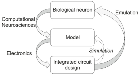
Figure 1. Design methodology (left-hand gray arrows) and validation of an integrated neuromimetic circuit (Right-hand gray arrow).
We wish here to reproduce the behavior of biological neurons to extend the hybrid technique, also called “dynamic-clamp,” (Le Masson et al., 1995) to Micro-Electrode Arrays (Bontorin et al., 2007). This technique consists of connecting artificial and biological neurons to create a real-time loop (Sorensen et al., 2004). A review of the motivation for using the hybrid technique to study biological cells can be found in Destexhe and Bal (2009). This technique has also been used with intracellular recordings to study the transmission of information from the retina (implemented by an analog retinal model of neuron) to the cortex through a hybrid thalamic network composed of a biological thalamic relay cell recorded in vitro and a model reticular cell providing feedback inhibition onto the biological neuron (Le Masson et al., 2002). The real-time feature of the hybrid technique extended to the Micro-Electrode Arrays would allow us to study the properties of larger biological networks. This extension of the hybrid technique has never been done.
In previous work, we designed several neuromimetic chips (Levi et al., 2008) included Galway chip that we used for this paper. Galway includes analog operators to compute Hodgkin–Huxley (HH) formalism and multi-synapses to build neural network. Our analog IC was optimized for reproducing a large variety of neuron behaviors thanks to tunable parameters. However the IC does not guarantee that the use of parameters extracted from a biological cell will reproduce the exact behavior of that cell. We choose to compensate for the process variation and the device mismatch through the tuning process. To demonstrate that our neuromimetic IC can emulate the most important properties of biological neurons, we use electrophysiological recordings as a reference.
To extend the hybrid technique, the aim is to build a biophysically realistic network model of the cerebral cortex which incorporates the diversity of intrinsic cell properties in the cortex by making use of reconfigurable integrated circuits (Saïghi et al., 2011). Such ICs are designed with two goals in mind: firstly to enable the construction of bio-realistic networks, and secondly to offer the possibility of dynamically tuning the model parameters. ICs are organized to form a simulation toolbox, so that a large variety of models can be implemented in real-time. Although our choice implies a costly design (Galway contains 105 pads, around 50000 components, its area is 10.5 mm2, and is power consumption is 550 mW), it is an interesting alternative to digital computation in simulation platforms for computational neurosciences in terms of simulation time–cost. For the simulation of one neuron, hardware system is not really relevant but seeing further, for a large scale network, the hardware system will be in real-time contrarily to the NEURON software. In addition, these ICs lead to neuromorphic network models that are typically highly scalable and able to emulate neural networks in real-time or much faster, independently of the underlying network size.
The choice of neural model is important for designing an analog tunable neuromimetic circuit. All models have advantages and drawbacks (Izhikevich, 2004). In our case, where the hybrid technique should allow one to better understand the biological phenomena, the chosen model has to be the most biologically plausible. We have no flops (floating point operations per second) limitation for our design thanks to the analog computation. Within the family of biologically plausible point neuron models, there is a group of conductance-based models, in which ionic and synaptic currents charge and discharge a capacitor representing the neuron membrane. All of these models find their origins in the HH model (Hodgkin and Huxley, 1952) which will be described in the next section. Moreover, conductance-based models and real-time processing at the sample level will be helpful for the hybrid technique. The neuroscientists can dynamically play with the model parameters that have a biophysical meaning and observe the effects on the biological cells.
Our chip, based on our library of analog operators, has a large range of validity domains for the parameter to reproduce different kind of neurons. The tuning of conductance-based analog neuromimetic chips has already been investigated by a few researchers (Shin and Koch, 1999; Simoni et al., 2004; Rasche and Douglas, 2007; Yu and Cauwenberghs, 2010). However, none of them compare their results with biological data. Simoni et al. (2004) and Yu and Cauwenberghs (2010) validate the tuning notably thanks to internal variables of the model which are not usually recorded in biological cells. Rasche and Douglas (2007) and Shin and Koch (1999) focus on the control of the firing rate versus stimulation. This dependency between frequency and input currents is used for the study of the network dynamic. However these neuromimetic designs were never compared to biological data. Moreover, the variety of implemented cell types is limited to the fast spiking (FS) neuron (Yu and Cauwenberghs, 2010) and also the regular spiking (RS) neuron (Shin and Koch, 1999; Rasche and Douglas, 2007). Only Simoni et al. (2004) presents more complex behaviors. Additionally, the chip tuning of neuromimetic circuits is also a current issue for other kinds of applications or models. Russel et al. (2010), Orchard et al. (2008) use a genetic algorithm to reproduce the activity of the Central Pattern Generator thanks to an adaptive integrate and fire model, while Brüderle (2010) has developed a technique for reproducing the statistical characteristics of the adaptive exponential integrate and fire model.
To fulfill our requirement, we selected the four most prominent electrophysiological classes: “FS,” “RS,” “intrinsically bursting” (IB), and “low-threshold spiking” (LTS) neurons, inspired from the classification of Connors and Gutnick (1990). This subdivision corresponds to classifying cells according to three qualitative criteria: (1) presence or absence of spike-frequency adaptation; (2) presence or absence of burst discharges from depolarizing stimuli; (3) presence or absence of burst (or any other type of) discharge following hyperpolarizing inputs (rebound response). In this paper, we present their implementation in our analog/digital neuromimetic chip dedicated to the simulation of cortical networks using the data and the electrophysiological recording presented in Pospischil et al. (2008).
In Section “Materials and Methods,” we present the methods that include the HH formalism, the implemented neural model, and the chip tuning method. The material part of this section presents the neuromimetic chip and the whole system for the parameter optimization. This is followed by the Section “Results” where we compare the biological and artificial neural behavior. Finally, in the last section, we discuss the outlooks of this research for improving the hybrid technique.
Materials and Methods
The Hodgkin–Huxley Formalism
We used the HH formalism as a design basis for our IC. Each ionic channel is represented by a time and voltage-dependent conductance: this electrophysiological description makes these models particularly well-suited to an implementation involving analog electronics. The main advantage of this formalism is that it relies on biophysically realistic parameters and describes individual ionic and synaptic conductances for each neuron in accordance with the dynamics of ionic channels. Electrical activity of a neuron is the consequence of the diffusion of different ionic species through its membrane. The HH formalism provides a set of equations and an equivalent electrical circuit (Figure 2), which describes the conductance interplay underlying the genesis of action potentials.
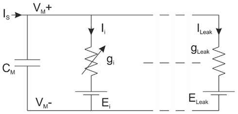
Figure 2. Equivalent electrical circuit of a neuron.
The current flowing across the membrane is integrated on the membrane capacitance, according to expression (1):
where VM is the membrane potential, CM is the membrane capacitance, Ii denotes the individual ionic currents of the model, ILeak the leakage current, and IS is a stimulation or a synaptic current. Ii is the current for a given type of channel, and its associated equation is:

where gi is the maximum conductance; m and h are gating variables for activation and inactivation, respectively, representing the fraction of open gates available at any given time and voltage.
Ei is the ion-specific reversal potential and p and q are integers. According to the first order differential Eq. 3, m relaxes back toward its associated steady-state value m∞, which is a sigmoid function of VM (4). The time constant for convergence is τm which is also voltage-dependent of VM.
In (4), VOffset,m and VSlope,m are the offset and the slope of the activation sigmoid respectively. The inactivation parameter h follows identical equations, except for the sign inside the brackets, which is positive.
The original equations proposed by HH describe sodium, potassium and leakage channels, with p = 3 and q = 1; p = 4 and q = 0; p = 0 and q = 0 respectively, in expression (2). These channels are responsible for action potential generation. For more complex activity patterns, such as bursting, rebound bursts or the discharge of action potentials with adaptation phenomena, additional channels such as L-Type calcium channel for bursting (p = 2 and q = 1), T-Type calcium channel for bursting (p = 2 and q = 1) and slow potassium channel (p = 1 and q = 0) have to be taken into account (Pospischil et al., 2008).
The Model Implemented in Our Integrated Circuit
We implemented in our chip the HH model with an approximation: we use a fixed time constant in (3). We chose this approximation to reduce the silicon area required by the neuron implementation in the chip. Consequently the only difference between the VLSI model and the HH models presented in Pospischil et al. (2008) is the approximation used for the gating variable. This approximation is obtained through the three following steps (Chen et al., 2010):
(a) Calculating αx(VM) and βx(VM) from Pospischil et al. (2008) over the range VM = [−100, 100] mV. The x subscript represents the activation or the inactivation term.
(b) Identifying the VOffset,x and VSlope,x terms in the sigmoid function that is equal to x∞ = αx(VM)/(αx(VM) + βx(VM)).
In addition, τx is calculated from τx = 1/(αx(VM) + βx(VM)) at VM about −70 mV. Empirically, the choice of −70 mV is the best value.
Four types of neurons (FS, RS, IB, and LTS) were emulated in our experiments. Table 1 summarizes the parameter values extracted from Pospischil et al. (2008) and adapted for the implementation in silicon.
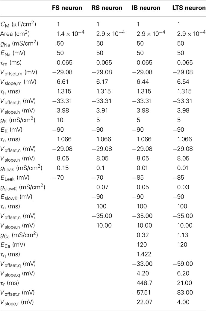
Table 1. Parameters of biological FS, RS, IB, and LTS neurons.
Even though we validate the behavior of the chip with measurements from biological cells, we also compare, thanks to MATLAB, the software simulations of HH and the simplified models to verify whether our approximation is accurate. Figure 3 presents the result for the four neurons studied. We observe in Figure 3A that the simplified FS model has dynamics comparable to the HH model, in terms of frequency, voltage range. The main difference between both lies in the waveform of the membrane voltage. Even though its dynamic is similar apart from the action potential, the width of the spike is larger for the HH simplified model. This difference appears for the four cases because we use similar values for the sodium and potassium channels, which generate the action potential and its shape. In Figure 3B, we see the behavior for the RS neuron. The instantaneous frequencies at the beginning are not the same even though the frequencies are identical after the adaption. Moreover, we observe a difference for the adaptation time constant even though there is the same number of spikes. This phenomenon is clearly due to the approximation of the adaptation time constant. We have chosen to work in steady-state conditions, which is justified mainly because cortical neurons in vivo operate in states of intense and sustained firing activity (Destexhe et al., 2003), in which case the adaptation mechanisms are expected to be at steady-state most of the time. Considering that the most important aspect is to obtain the same frequency after the adaptation period, then this approximation is relevant. The same observations about the initial and final frequencies can be made for the IB neuron (see Figure 3C). The initial frequencies are similar while the final frequencies are identical. For both traces, there is the same number of spikes. As with the RS neuron, our approximation is validated. Finally, we observe in Figure 3D the LTS neuron response to depolarization stimulation current. Even though the global behaviors are similar, we note that the time when the spike occurs is different. We manually tried different values for the time constant of the calcium current (see Table 1) and we choose the most acceptable. In the case of the membrane voltage dynamics comparison, the approximations of the time constants have a consequence on the spike shape and/or on the spike frequency. We expected those differences, however, as explained above, we compare the HH and simplified model with software simulations to check if those approximations are suitable. On the other hand, the validation of the neuromimetic IC tuning will follow the protocol presented in Figure 1, which shows a comparison of the IC measurements with electrophysiological recordings, because we wish to emulate biological neurons with our neuromimetic chip to build a bio-artificial network that operates in real-time.
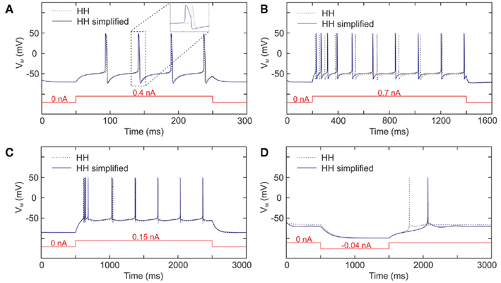
Figure 3. Membrane voltage software simulations of the Hodgkin–Huxley model (dotted line), and model implemented in VLSI (solid line) for (A) FS neuron, (B) RS neuron, (C) IB neuron, and (D) LTS neuron.
Neuromimetic Chip and Dedicated Board
Our goal is to build a neural simulator based on a hardware implementation able to reproduce the dynamics of the biological neurons. Our system is composed of our most recent chip called Galway (Figure 4) and the dedicated board named Ekerö. This chip includes analog operators for the computation of the HH formalism, and for the construction of neural networks, multi-synapses that consist of gathering all synaptic inputs in one electronic input (Alvado et al., 2003).
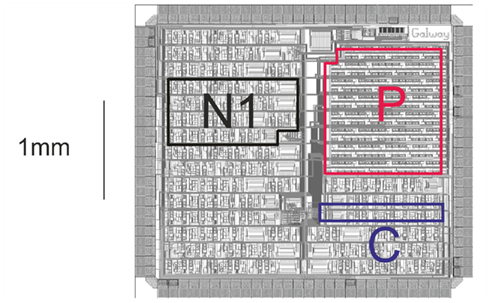
Figure 4. Microphotograph of the chip Galway. Where, P is the part for analog memories, C for conductance, and N1 for neuron 1.
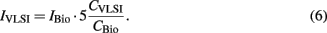
Analog memories have been embedded to allow the storage of the parameter values determined by the HH formalism. Taking into account integration constraints of the microelectronic design, and in order to increase its dynamic range and noise immunity, we applied a ×5 gain factor to the biological voltages:

Let CVLSI and CBio represent the membrane capacitances of artificial and biological neurons, respectively. The conductance mapping is proportional to the capacitance ratio as gVLSI/gBio = CVLSI/CBio. The current mapping then equals the product of the voltage and conductance mappings, i.e.,
With the Galway chip, CVLSI = 3.3 nF and the biological neurons have CBio = CM·Area with CM and Area given in Table 1. The chip was designed in full-custom mode, based on a BiCMOS SiGe 0.35 μm technology process from austriamicrosystems. This IC contains five neurons: one FS neuron with three conductances, four RS neurons with four conductances, and for IB or LTS neuron, one additional conductance which can be connected to the last RS neuron. Tuning all the neurons involves setting 205 V parameters.
This IC is embedded in a six-layer full-custom board called Ekerö. This board hosts four Galway ASICs, representing a total of 20 neurons. Several Ekerö boards have already been designed for the next neural network experiments. Digital synaptic inputs and spike detection outputs are individually connected to a FPGA, which is connected to a host computer. This allows the user to send and receive data to/from the chips. Some of the coaxial connectors are used to provide analog outputs for the observation of ionic currents and membrane voltages on an oscilloscope. The others are used for analog inputs to stimulate the silicon neuron or to impose a membrane voltage.
Automated Tuning System for the Neuromimetic Chip
The HH model is complex, and is strongly dependent on non-linear equations involving a large number of parameters, which ranges from 15 parameters for the very simple model of a FS neuron to 28 parameters for neurons with more complex behaviors (Table 1). The tuning of this model, in order to reproduce a given neuronal signal, is thus difficult. Moreover, due to the fabrication process, there are significant differences between the expected and actual outputs of the chips (Saïghi et al., 2008). It is therefore necessary to further adjust the parameters in order for the neuromimetic circuits’ outputs to agree with the neuronal activity. As hand tuning is very time-consuming, due to the model’s sensitivity to these parameter values and due to the large number of variables, an automated tuning of the parameters is mandatory. In Rossant et al. (2010), there is a software solution for automatic fitting of spiking neuron models to electrophysiological recordings but this fitting procedure could be very time-consuming both in terms of computer simulations and in terms of code writing. A Systematic method for configuring VLSI Networks of Spiking Neurons was proposed by Neftci et al. (2011) that describes a parameter mapping technique that permits an automatic configuration of VLSI neural network. For single cell models such as the HH model, techniques based on ionic current recordings can be used to estimate the parameters. The most well known method is the “voltage-clamp” introduced by Cole (1949), and later used by Hodgkin and Huxley (1952). We developed a new estimation method for the characterization of the HH formalism (Buhry et al., 2011). This method is an alternative technique to the estimation methods associated with voltage-clamp measurements. It uses recordings in the voltage-clamp mode, but is based on an evolutionary algorithm: the differential evolution (DE) algorithm (Storn and Price, 1997). Like genetic algorithm, DE belongs to the class of Evolutionary Algorithms. It uses mechanisms inspired by biological evolution: reproduction, mutation, recombination, and selection (Storn and Price, 1997). Candidate solutions to the optimization problem play the role of individuals in a population. DE consists in generating a population of vectors which is the population of the whole individuals. The parameters contained in a vector are also called genes that are, in our case, gi, τ, Ei, VOffset, and VSlope. This population is initialized randomly with a uniform law within the boundary constraints of the model. Then, a new trial individual is built by means of three operations: Differentiation, Recombination, and Selection (Feoktistov and Janai, 2004).
The DE algorithm requires data recorded in voltage-clamp mode, which involves the observation of one ionic current, when membrane voltage levels are successively applied with different steps. We use the host computer to control an oscilloscope and an arbitrary waveform generator. The complete program has to drive the instruments and the neuromorphic system, and also computes the DE algorithm. Figure 5 shows a schematic diagram of the experimental implementation described in the following steps:
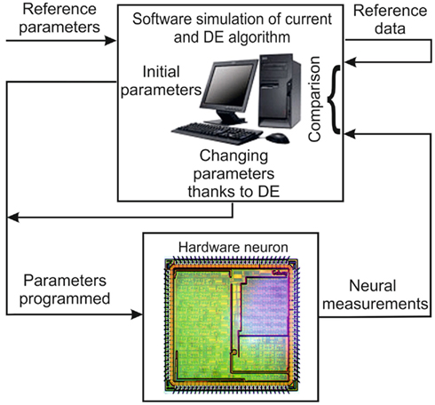
Figure 5. Schematic diagram of the automated tuning system.
– The user chooses the model set for the ionic current.
– The program successively transmits the population of parameters and generates the different steps of the imposed voltage. Each ionic channel is optimized separately.
– The computer stores the imposed voltages and the current responses measured on the Ekerö board.
– The program calculates the theoretical current response, using the model parameters and the measured imposed voltages. Then it calculates the fitness or cost function to be minimized, that is defined by the quadratic error between the theoretical current response of an ionic channel and the current response of the same ionic channel measured from the IC while the membrane voltage is clamped.
– The program uses the DE algorithm (Differentiation, Recombination, and Selection) to choose the new population of parameters, before sending it back to the chip.
However the chip tuning technique is not applied to the stimulation current generator. Due to the process and component mismatch, there is an error current between the expected and actual current. Therefore, a conversion rule on the IStim_Hard hardware stimulation current is applied to compensate for that error current. IStim_Hard obeys the rule:

We defined empirically acomp and bcomp parameters to match the lowest and highest firing rates versus stimulation current in reference to the biological data. Finally, the hardware neuron model is composed of the optimized parameters from the theoretical values in Table 1, CVLSI and the pair acomp and bcomp from (7).
Results
Pursuant to our goal of implementing the “prototypical” types of neurons present in neocortex in VLSI hardware, we successively consider the four different cell classes (FS, RS, IB, and LTS) and show the results of our VLSI chip behavior after tuning. For the comparison of the behaviors between the biological and the hardware neurons, we implemented the parameters shown in Table 1, in which all electronic values are converted into biological scale as explained in Eqs 5–7, and all biological data are reproduced from Pospischil et al. (2008).
Fast Spiking Neurons
The FS neurons correspond to inhibitory neurons. FS cells respond to depolarizing pulses by producing high frequency trains of action potentials without adaptation (Figure 6A). FS cells are also the simplest kind of model, as only the conductances for generating spikes (INa, IK, ILeak) are needed. Figure 6B shows the hardware FS neuron response with the application of a stimulation current. In both cases, the stimulation current of 0.7 nA is applied for 125 ms. We observe identical resting potential about −66 mV and similar voltage range for the membrane voltage.
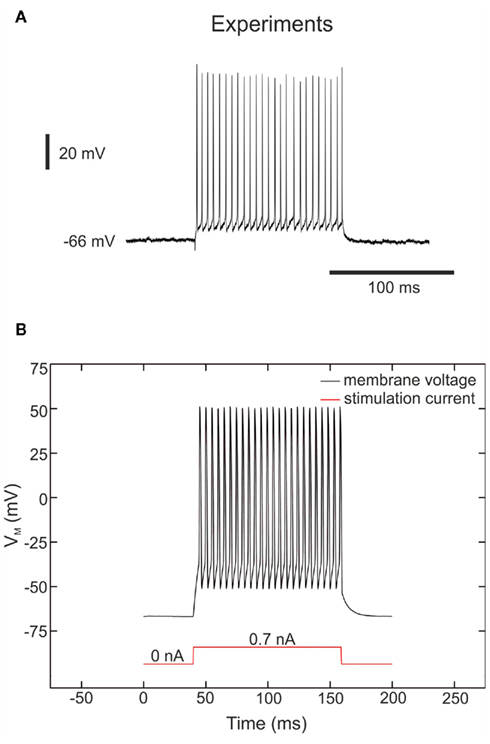
Figure 6. Membrane voltage of “fast spiking” neurons. (A) Response of a fast spiking neuron based on ferret visual cortex in vitro (Pospischil et al., 2008; experimental data from Thierry Bal, CNRS) to injection of a depolarizing current pulse (0.7 nA). (B) Measurements of the FS hardware neuron at a depolarizing current pulse (0.7 nA). The VLSI voltage measurements are divided by 5 in the figure in accordance with (5).
However, the comparison of the electrical behavior of the artificial neuron with the biological target must go further. We also apply different current pulses for plotting the frequency–current relations (firing rates) of the FS as shown in Figure 7. The FS neuron has no adaptation, and thus its frequency is constant during the stimulation. We plot in Figure 7A the average of the firing rates for 40 FS neurons after the tuning step, we also plot the variability of data using the error bars. The stimulation current follows the rule presented in (6) so far. We observe the effect of the electronic leakage current on the curves dispersion. In Figure 7B, we apply Eq. 7. The hardware data plotted are the average and the SD for the 40 neurons. For the biological reference, we take the mean frequency for each stimulation current from Figure 3B in Pospischil et al. (2008). The biological data are composed only of four points. For each of those points, the artificial neuron frequency matches to that of the biological neuron.
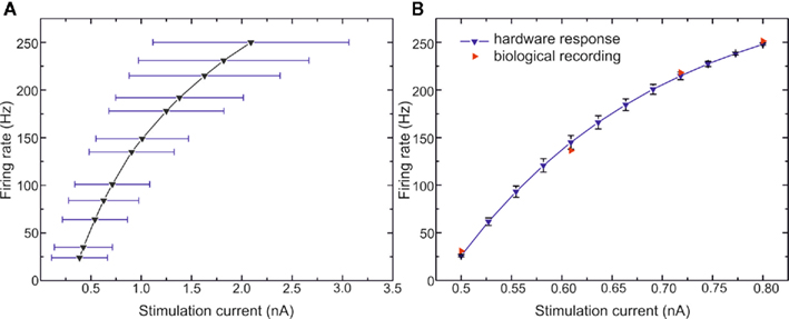
Figure 7. Frequency versus stimulation current curves of FS neurons. (A) 40 VLSI FS neurons tuned with model parameters from Table 1 and automated tuning technique. The stimulation current follows the rule IVLSI = 5·IBio·CVLSI/CBio. (B) Biological measurements of FS neuron from Pospischil et al. (2008) and the 40 VLSI neurons with the rule (7) for the stimulation current.
We present in Table 2 the parameter values for 40 FS neurons. We do not present the results for the time constants because the implemented values depend on external capacitors for which we did not measure the exact value. The theoretical values are provided by the model. The implemented values are computed by the optimization algorithm. In any event, we observed a large discrepancy for all parameters which confirms the necessity of the tuning step. The results for the RS are similar because the sodium, potassium, and leakage currents are the same except for three parameters and the four new parameters for the IslowK channel present the same characteristics. Due to the scarcity of data for the LTS and IB, the statistical results are not meaningful. That is why we will not present the same table for the RS, IB, and LTS neurons.
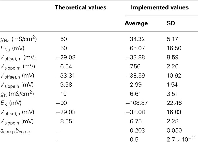
Table 2. Theoretical and implemented parameter values for 40 FS neurons.
Thanks to the comparison of the membrane voltage and the frequency versus stimulation current between biological and analog hardware neuron, we conclude that the simplification of the model and its implementation in silicon are well-suited to reproduce the behavior of the FS neuron.
Regular Spiking Neurons
Another common cell class in neocortex is called the RS neuron, which is in general excitatory and most often corresponds to spiny pyramidal-cell morphology. The typical responses of RS cells to depolarizing current pulses are trains of spikes with adaptation, as illustrated for a typical RS cell from ferret visual cortex in vitro (Figure 8A). The simplest model of RS cells consists of conductances for generating spikes (INa, IK, ILeak; Traub and Miles, 1991), and in addition, a slow potassium current activated by depolarization (Yamada et al., 1989). This model reproduces the typical firing characteristics of RS cells as recorded in ferret visual cortex in vitro. After tuning our chip following this four conductance model, we apply a stimulation current of 0.7 nA for 200 ms as in the biological experiment to compare the electronic and biological behaviors (Figure 8B).
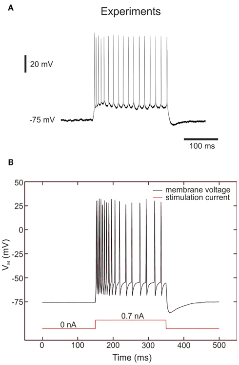
Figure 8. Membrane voltage of “Regular spiking” neurons. (A) Intracellular recordings of regular spiking neurons in ferret visual cortex in vitro (Pospischil et al., 2008; experimental data from Thierry Bal, CNRS). Responses to injection of a depolarizing current pulse (0.7 nA). (B) Measurements of the RS hardware neuron at a depolarizing current pulse (0.7 nA) showing the typical response of a RS neuron, with spike-frequency adaptation. The VLSI voltage measurements are divided by 5 in the figure in accordance with Eq. 5.
As for the FS neuron, we observe that the resting potential is about −75 mV and the membrane voltage range is similar. Moreover, we observe in both cases a high frequency discharge on the first part of the response and then the frequency decreases slowly due to the adaptation phenomenon. The main difference between the two traces in Figure 8 is the behavior during the period between two spikes. We can also observe the same kind of difference in Figure 1 from Pospischil et al. (2008). Thus we consider that the hardware membrane voltage reproduces the biological behavior to the utmost of its abilities.
The behavior of the two neurons has been investigated further. We apply different current pulses for plotting the frequency–current relations of the RS as shown in Figure 9. The RS neuron has an adaptation channel, and thus we plot the instantaneous frequency (inverse of the interspike time interval) for the first and tenth spikes. Figure 9 shows the hardware firing rates for the first and the tenth spikes from 20 RS neurons after applying the conversion rule presented in (7). We plot the average and the SD for the 20 hardware RS neurons. For the biological data, we plot the biological recordings presented in Figure 1 from Pospischil et al. (2008). The first spikes are similar for the hardware and the biological cells. The behavior for the tenth spike is different, especially for the high frequency. However, one can observe the same difference as with the original model in Figure 1 in Pospischil et al. (2008). The other intermediate instantaneous frequencies do not match as well (not plotted here to avoid confusing the figure). We can observe this phenomenon in Figure 8 where the firing frequencies at the beginning of the activity are not identical. As explained in the section concerning the model implementation in the chip, that behavior is the result of the tradeoff between the firing rate after adaption and the adaptation time constant to reach that adaptation. We decided to focus more on the first feature. Despite the fixed adaptation time constant, we reproduce the behavior of the RS neuron in terms of the membrane voltage, and the spike frequencies before and after adaptation.
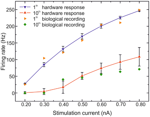
Figure 9. Frequency versus stimulation current curves of RS neurons. Biological measurements of RS neuron from Pospischil et al. (2008) and the 20 VLSI neurons with the rule (7) for the stimulation current.
Intrinsically Bursting Neurons
Another very common cell class is the IB neuron. The IB cells represent a few percent of the recorded cells in primary sensory cortex, both in vivo and in vitro. This kind of neuron generates bursts of action potentials following depolarizing stimuli and then the firing rate decreases suddenly.
To generate the bursting behavior, we extended the previous model of RS cell by adding the L-type calcium current. Because we have few experimental recordings for this type of cell, the frequency versus stimulation current may not be significant. For comparison, we apply to biological and hardware neurons the same stimulation currents in Figures 10A,B, respectively. For the weakest stimulation currents (from 0 to 0.5 nA), we observe similar membrane depolarization. For the 0.6-nA stimulation, we observe two spikes in both cases even though the frequency in the biological cell is higher. For the biggest stimulation currents (≥0.7 nA), we notice an initial fast activity (the neuron repeatedly fires discrete groups or bursts of spikes) followed by a train of action potentials. The hardware neuron is in accordance with biological time scale. However, we can observe two differences. The first one is the behavior of the membrane voltage between two spikes during the train of action potentials. The VLSI membrane voltage has a hyperpolarization behavior before a spike occurs. The second difference is the duration of the initial fast activity. The high frequency lasts longer for the VLSI neurons. Even though the membrane voltages are comparable for the switching frequencies behavior, the effect of the L-type calcium current is to suddenly bring the neuron from one spiking frequency to another. As in Pospischil et al. (2008), we reproduce the IB cell behavior to the detriment of the duration of the first oscillatory phase and the membrane voltage behavior during the second phase. Those two differences were also observed in the original model on Figure 6 in Pospischil et al. (2008). Consequently, we consider in this case that we adequately reproduce the targeted biological behavior.
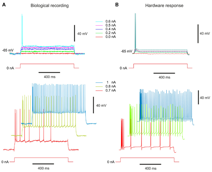
Figure 10. Membrane voltage of “Intrinsically bursting” neurons. (A) Intrinsically bursting (IB) cell from guinea-pig somatosensory cortex in vitro modified from Pospischil et al., 2008; experimental data from Cyril Monier and Yves Frégnac, CNRS). Response to different depolarizing current pulses. (B) Measurements of the IB hardware neuron at same depolarizing current pulses. The VLSI voltage measurements are divided by 5 in the figure. The stimulation current follows the rule (6).
Low-Threshold Spiking Neurons
In Destexhe et al. (2001), LTS activities are described in a significant fraction (about 10%) of intracellularly recorded cells in cat association cortex in vivo. These LTS neurons generate adapting trains of action potentials in response to depolarizing current injection, similar to the classic “regular spiking” response of cortical neurons. In addition, they generate a burst of action potentials in response to injection of hyperpolarizing current pulses (Figure 11C). This property was also identified in deep layers of guinea-pig cerebral cortex in vitro (De la Peña and Geijo-Barrientos, 1996) and was shown to be due to the presence of the T-type (low-threshold) calcium current.
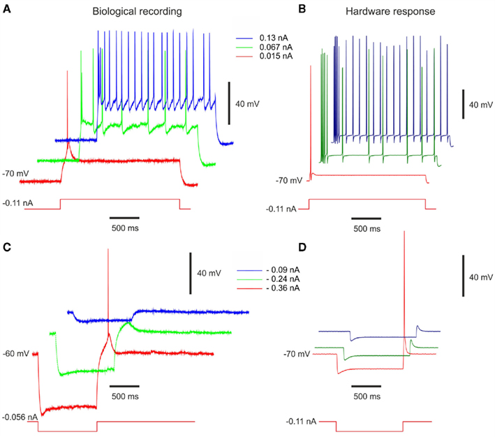
Figure 11. Measurements of LTS-Bursting behavior. Response of biological LTS cells from rat somatosensory cortex in vitro (Pospischil et al., 2008; experimental data from Maria Toledo-Rodriguez and Henry Markram, EPFL) to (A) depolarizing and (C) hyperpolarizing stimulation pulses. Measurements of the LTS hardware neuron with the same (B) depolarizing and (D) hyperpolarizing stimulation currents applied. The VLSI voltage measurements are divided by 5 in the figure. The stimulation current follows the rule (7).
In this case, we extended the previous model of the RS cell by adding the T-type calcium current. As for the IB, the recordings obtained from the LTS neuron are rare. The main comparison is also the behavior of the membrane voltage. The positive stimulation currents in Figures 11A,B show the “regular spiking” behavior of the LTS cell. The firing rate decreases while the stimulation current is applied. In both cases, the initial value of the membrane voltage is equal to −70 mV for a DC current equal to −0.11 nA. As for the RS cell, the frequency of the hardware neuron is higher than the biological cell. This behavior is consistent due to the very similar parameters of RS and LTS cells in Table 1. The negative stimulation currents produce the rebound burst activity in Figures 11C,D. The initial values of the biological cell are different in Figures 11A,C due to different DC stimulation current, which are equal to −0.056 and −0.11 nA for the biological and VLSI neuron, respectively. When the stimulation current is applied, the hardware LTS is less depolarized than the biological neuron. However, when the stimulation ends, our hardware LTS neuron reproduces the same behavior than the biological cell. We also observe a slightly higher depolarization for the hardware neuron with −0.09 and −0.24 nA current stimulation. For −0.36 nA, one spike occurs in both cases. We consider that we adequately reproduce the targeted biological behavior of the LTS cell.
Discussion
The understanding of neuronal circuits is a great challenge which involves a large number of researchers from different disciplinary fields. All strategies, including neuromorphic engineering, contribute to that understanding. Even though Mead (1989) defined neuromorphic engineering as the use of the characteristics of analog components for neuronal computation, modern neuromorphic designers implement analog, digital, or mixed systems. Among all neuromorphic designs, we notice that a few groups use conductance-based-model, which belongs to the most biologically plausible single point model, with parameters tuned to understand the biology (Shin and Koch, 1999; Simoni et al., 2004; Rasche and Douglas, 2007; Yu and Cauwenberghs, 2010). However these neuromimetic designs were never compared to biological data. Additionally, we notice that the chip tuning of neuromimetic circuits is also used with integrate and fire model (Orchard et al., 2008; Russel et al., 2010) and adaptive exponential integrate and fire model (Brüderle, 2010) to reproduce biological network activities.
In our case, we wish to insert silicon neurons among biological neurons. We decided to qualitatively compare the dynamics of our silicon circuit to biological cells with a level of details that was never done with silicon neuron. To reach our goal, we propose a simplified version of the HH formalism and the appropriate parameter sets of the FS, RS, IB, and LTS neurons that can be implemented in our analog neuromimetic chip. The models considered here are the simplest types of biophysical models where the intrinsic properties arise from voltage-dependent conductances which are described by differential equations (HH type models). The main motivation for this model type is the strong correspondence of their parameters with those in biology. We used the fixed time constant for the gating variables to simplify the model and validated this simplified model thanks to the comparison with software simulations for the four neuron types. We then tuned our chip following those models and a full-custom and dedicated technique. This optimization method, based on the DE algorithm proposed in Buhry et al. (2011), is an alternative to the estimation methods associated with voltage-clamp measurements. In any event, we observed a large discrepancy for all parameters which confirms the necessity of the tuning step. As with any circular problem, we chose an arbitrary starting point to solve it. Even though the optimization phase of our tunable chip is time-consuming, we will save time in the emulation phase thanks to three features. First, our chip requires only one tuning of its parameters. The parameter sets are then stored in a database and the required parameters are loaded into the chip as needed to emulate any given cell type. Second, the model parameters can be modified on-line at any time. Third, the neuron type can also be modified on-line by connecting/disconnecting an ionic channel and/or modifying a few parameters. For example, the burst in IB cell can be modulated by the value of the conductance or time constants of the calcium current. All these on-line changes take only a few microseconds. This will enable the user to alter parameters in order to study their effect on the dynamic of the biological network. Finally, we tested the parameters obtained by comparing the behavior of the membrane voltage in the recordings of biological cells with membrane voltages simulated with our chip. This comparison is doable thanks to the translations rules between biological and hardware neurons based on the chip characteristics. We directly compare the behavior of our chip with biological recordings. Our results show that our system is able to reproduce the main features of four common classes of cortical cells.
In the near future, we plan to tune hundreds of neurons and create a large artificial network composed of 10% of IB and LTS, 20% of FS and the remainder of RS neurons. These neuromimetic chips will be embedded in a full-custom system that will allow us to scale up the neuromimetic network to about 100 real-time and biophysically realistic neurons. This system will help be useful for understanding neural network dynamics using the hybrid technique. The hybrid technique has already provided some valuable results at the single cell and small network levels. Any extension of the hybrid technique to larger networks should contribute to the understanding of neuronal circuit function. The following characteristics are necessary: (a) operate in biological real-time, (b) use biophysically realistic models, and (c) permit tuning. Thanks to the parallel nature of the computations, the analog design can easily have real-time characteristics even for the most accurate neural models. However, for the system to be truly useful, the chip designers must propose an associated tuning technique for it. All of these specifications are included into our system. Then compared with the original hybrid technique where one artificial neuron was connected to one biological cell (Le Masson et al., 2002), a network this large will be enough to employ the hybrid technique with Micro-Electrode Arrays composed of 64 electrodes. Due to the parallel nature of the circuit, the real-time properties of our system will easily be preserved independently the number and the complexity of the emulated neurons. This extension of hybrid technique has never been done.
Conflict of Interest Statement
The authors declare that the research was conducted in the absence of any commercial or financial relationships that could be construed as a potential conflict of interest.
Acknowledgments
The authors would like to thank Dr. Philippe Pouliquen for proofreading the material. This project was partly supported by funding under the Seventh Research Framework Program of the European Union (FP7-PEOPLE-ITN-2008) under the Grant n°237955 (FACETS-ITN), (FP7-FET-Proactive) under the Grant n°269921 (BrainScales), under the PIR Neuroinformatique of the CNRS (ECRéN), and a grant from the French national program “Pour les Femmes et la Sciences” of L’Oréal France – UNESCO – Académie des Sciences.
References
Alvado, L., Saïghi, S., Tomas, J., and Renaud, S. (2003). “An exponential-decay synapse integrated circuit for bio-inspired neural networks,” in Seventh International Work-Conference on Artificial and Natural Networks, Mahon, Vol. 1, 670–677.
Bontorin, G., Renaud, S., Garenne, A., Alvado, L., Le Masson, G., and Tomas, J. (2007). “A real-time closed-loop setup for hybrid neural networks,” in 29th Annual International Conference of the IEEE Engineering in Medicine and Biology Society, Lyon, 3004–3007.
Brette, R., Rudolph, M., Carnevale, T., Hines, M., Beeman, D., Bower, J. M., Diesmann, M., Morrison, A., Goodman, P. H. F. C., Harris, J., Zirpe, M., Natschläger, T., Pecevski, D., Ermentrout, B., Djurfeldt, M., Lansner, A., Rochel, O., Vieville, T., Muller, E., Davison, A. P., Boustani, S. E., and Destexhe, A. (2007). Simulation of networks of spiking neurons: a review of tools and strategies. J. Comput. Neurosci. 23, 349–398.
Brüderle, D. (2010). Neuroscientific Modeling with a Mixed-Signal VLSI Hardware System. Ph.D. dissertation, Ruperto-Carola University of Heildeberg, Bordeaux, Germany, 229.
Brüderle, D., Petrovici, M., Vogginger, B., Ehrlich, M., Pfeil, T., Millner, S., Grübl, A., Wendt, K., Müller, E., Schwartz, M. O., De Oliveira, D., Jeltsch, S., Fieres, J., Schilling, M., Müller, P., Breitwieser, O., Petkov, V., Muller, L., Davison, A., Krishnamurthy, P., Kremkow, J., Lundqvist, M., Muller, E., Partzsch, J., Scholze, S., Zühl, L., Mayr, C., Destexhe, A., Diesmann, M., Potjans, T., Lansner, A., Schüffny, R., Schemmel, J., and Meier, K. (2011). A comprehensive workflow for general-purpose neural modeling with highly configurable neuromorphic hardware systems. Biol. Cybern. 104, 263–296.
Buhry, L., Grassia, F., Giremus, A., Grivel, E., Renaud, S., and Saïghi, S. (2011). Automated parameter estimation of the Hodgkin – Huxley model using the differential evolution algorithm: application to neuromimetic analog integrated circuits. Neural. Comput. 23, 2599–2625.
Chen, H., Saïghi, S., Buhry, L., and Renaud, S. (2010). Real-time simulation of biologically realistic stochastic neurons in VLSI. IEEE Trans. Neural Netw. 21, 1511–1517.
Cole, K. S. (1949). Dynamic electrical characteristics of the squid axon membrane. Arch. Sci. Physiol. (Paris) 3, 253–258.
Connors, B. W., and Gutnick, M. J. (1990). Intrinsic firing patterns of diverse neocortical neurons. Trends Neurosci. 13, 99–104.
Davison, A. P., Hines, M., and Muller, E. (2009). Trends in programming languages for neuroscience simulations. Front. Neurosci. 3:3 doi:10.3389/neuro.01.036.2009
De la Peña, E., and Geijo-Barrientos, E. (1996). Laminar organization, morphology and physiological properties of pyramidal neurons that have the low-threshold calcium current in the guinea-pig frontal cortex. J. Neurosci. 16, 5301–5311.
Destexhe, A., and Bal, T. (2009). Dynamical-Clamp: From Principles to Applications. New York, NY: Springer.
Destexhe, A., Contreras, D., and Steriade, M. (2001). LTS cells in cerebral cortex and their role in generating spike-and-wave oscillations. Neurocomputing 38, 555–563.
Destexhe, A., Rudolph, M., and Paré, D. (2003). The high-conductance state of neocortical neurons in vivo. Nat. Rev. Neurosci. 4, 739–751.
Feoktistov, V., and Janai, S. (2004). “Generalization of the strategies in differential evolution,” in IEEE, 18th International Parallel and Distributed Processing Symposium, Sante-Fe, NM, 2341–2346.
Hodgkin, A. L., and Huxley, A. F. (1952). A quantitative description of membrane current and its application to conduction and excitation nerve. J. Physiol. (Lond.) 117, 500–544.
Indiveri, G., Linares-Barranco, B., Hamilton, TJ., van Schaik, A., Etienne-Cummings, R., Delbruck, T., Liu, S. C., Dudek, P., Häfliger, P., Renaud, S., Schemmel, J., Cauwenberghs, G., Arthur, J., Hynna, K., Folowosele, F., Saighi, S., Serrano-Gotarredona, T., Wijekoon, J., Wang, Y., and Boahen, K. (2011). Neuromorphic silicon neuron circuits. Front. Neurosci. 5:73. doi:10.3389/fnins.2011.00073
Izhikevich, E. (2004). Which model to use for cortical spiking neurons? IEEE Trans. Neural Netw. 15, 1063–1070.
Le Masson, G., Le Masson, S., and Moulins, M. (1995). From conductances to neural network properties: analysis of simple circuits using the hybrid network method. Prog. Biophys. Mol. Biol. 64, 201–220.
Le Masson, G., Renaud-Le Masson, S., Debay, D., and Bal, T. (2002). Feedback inhibition controls spike transfer in hybrid thalamic circuits. Nature 417, 854–858.
Levi, T., Lewis, N., Saïghi, S., Tomas, J., Bornat, Y., and Renaud, S. (2008). “Neuromimetic integrated circuits,” in VLSI Circuits for Biomedical Applications, ed. I. Kris (Boston: Artech House), 241–264.
Misra, J., and Saha, I. (2010). Artificial neural networks in hardware: A survey of two decades of progress. Neurocomputing 74, 239–255.
Neftci, E., Chicca, E., Indiveri, G., and Douglas, R. (2011). A Systematic method for configuring VLSI networks of spiking neurons. Neural. Comput. 23, 2457–2497.
Orchard, G., Russel, A., Mazurek, K., Tenore, F., and Etienne-Cummings, R. (2008). “Configuring silicon neural networks using genetic algorithms,” in International Conference on Biomedical Circuits and Systems, Seattle, WA, 1048–1051.
Pospischil, M., Toledo-Rodriguez, M., Monier, C., Piwkowska, Z., Bal, T., Frégnac, Y., Markram, H., and Destexhe, A. (2008). Minimal Hodgkin-Huxley type models for different classes of cortical and thalamic neurons. Biol. Cybern. 99, 427–441.
Rasche, C., and Douglas, R. (2007). An improved silicon neuron. Analog Integr. Circuits Signal Process. 23, 227–236.
Rossant, C., Goodman, D. F. M., Platkiewicz, J., and Brette, R. (2010). Automatic fitting of spiking neuron models to electrophysiological recordings. Front. Neuroinformatics 4:2. doi:10.3389/neuro.11.002.2010
Russel, A., Orchard, G., Dong, T., Mihalas, S., Neibur, E., Tapson, J., and Etienne-Cummings, R. (2010). Optimization methods for spiking neurons and networks. IEEE Trans. Neural Netw. 21, 1950–1962.
Saïghi, S., Bornat, Y., Tomas, J., Le Masson, G., and Renaud, S. (2011). A library of analog operators based on the Hodgkin-Huxley formalism for the design of tunable, real-time, silicon neurons. IEEE Trans. Biomed. Circuits Syst. 5, 3–19.
Saïghi, S., Buhry, L., Bornat, Y., N’Kaoua, G., Tomas, J., and Renaud, S. (2008). “Adjusting the neurons models in neuromimetic ICs using the voltage-clamp technique,” in InternationaI Symposium on Circuits and System, Seattle, WA, 1564–1567.
Shin, J., and Koch, C. (1999). Dynamic range and sensitivity adaptation in a silicon spiking neuron. IEEE Trans. Neural Netw. 10, 1232–1238.
Simoni, M. F., Cymbalyuk, G. S., Sorensen, M. E., Calabrese, R. L., and DeWeerth, S. P. (2004). A multiconductance silicon neuron with biologically matched dynamics. IEEE Trans. Biomed. Eng. 51, 342–354.
Sorensen, M., DeWeerth, S., Cymbalyuk, G., and Calabrese, R. L. (2004). Using a hybrid neural system to reveal regulation of neuronal network activity by an intrinsic current. J. Neurosci. 24, 5427–5438.
Storn, R., and Price, K. (1997). Differential evolution – a simple and efficient heuristic for global optimization over continuous spaces. J. Glob. Optim. 11, 341–359.
Traub, R. D., and Miles, R. (1991). Neuronal Networks of the Hippocampus. Cambridge: Cambridge University Press.
Wang, M., Yan, B., Hu, J., and Li, P. (2011). “Simulation of large neuronal networks with biophysically accurate models on graphics processors,” in IEEE International Joint Conference on Neural Networks, San Jose, CA, 3184–3193.
Yamada, W. M., Koch, C., and Adams, P. R. (1989). “Multiple channels and calcium dynamics,” in Methods in Neuronal Modeling: From Synapses to Networks, eds C. Koch and I. Segev (Cambridge, MA: Bradford Book, The MIT Press), 97–133.
Keywords: neuromimetic analog integrated circuits, biological neuron modeling, spiking neural networks
Citation: Grassia F, Buhry L, Lévi T, Tomas J, Destexhe A and Saïghi S (2011) Tunable neuromimetic integrated system for emulating cortical neuron models. Front. Neurosci. 5:134. doi: 10.3389/fnins.2011.00134
Received: 15 August 2011;
Accepted: 18 November 2011;
Published online: 07 December 2011.
Edited by:
Gert Cauwenberghs, University of California San Diego, USAReviewed by:
Theodore Yu, University of California San Diego, USAEmre Neftci, Institute of Neuroinformatics, Switzerland
Peiran Gao, Stanford University, USA
Copyright: © 2011 Grassia, Buhry, Lévi, Tomas, Destexhe and Saïghi. This is an open-access article distributed under the terms of the Creative Commons Attribution Non Commercial License, which permits non-commercial use, distribution, and reproduction in other forums, provided the original authors and source are credited.
*Correspondence: Sylvain Saïghi, Laboratoire d’Intégration du Matériau au Système, UMR CNRS 5218, Université de Bordeaux, 351 Cours de la Libération, 33405 Talence, France. e-mail: sylvain.saighi@ims-bordeaux.fr
†Present address: Laure Buhry, Mercator Research Group “Structure of Memory,” Ruhr-Universität Bochum, Bochum, Germany.