 Suzan Meijs
 Morten Fjorback2
 Carina Jensen
 Nico J. M. Rijkhoff
- 1SMI, Department of Health, Science and Technology, Aalborg University, Aalborg, Denmark
- 2Neurodan A/S, Aalborg, Denmark
- 3Danish Technological Institute, Århus, Denmark
The in vivo electrochemical behavior of titanium nitride (TiN) nerve stimulation electrodes was compared to their in vitro behavior for a period of 90 days. Ten electrodes were implanted in two Göttingen minipigs. Four of these were used for electrical stimulation and electrochemical measurements. Five electrodes were kept in Ringer's solution at 37.5°C, of which four were used for electrical stimulation and electrochemical measurements. The voltage transients measured in vivo were 13 times greater than in vitro at implantation and they continued to increase with time. The electrochemical properties in vivo and the tissue resistance (Rtissue) followed a similar trend with time. There was no consistent significant difference between the electrochemical properties of the in vivo and in vitro electrodes after the implanted period. The differences between the in vivo and in vitro electrodes during the implanted period show that the evaluation of electrochemical performance of implantable stimulation electrodes cannot be substituted with in vitro measurements. After the implanted period, however, the performance of the in vivo and in vitro electrodes in saline was similar. In addition, the changes observed over time during the post-implantation period regarding the electrochemical properties of the in vivo electrodes and Rtissue were similar, which indicates that these changes are due to the foreign body response to implantation.
Introduction
Peripheral nerve stimulation electrodes are currently applied among others to restore vision, hearing, movement, breathing, continence, and to relieve pain (Navarro et al., 2005; Stieglitz and Meyer, 2006; Zhou and Greenbaum, 2009). It is advantageous to make such electrodes as small as possible to minimize tissue trauma, while reducing the risk of activating other excitable tissue (Stieglitz and Meyer, 2006). However, when attempting to achieve a high level of selectivity, the aim to minimize the amount of tissue trauma is often compromised (Navarro et al., 2005). In addition, a small surface area limits transfer of charge, leading to a small volume of tissue that can be excited. This increases the risk of losing the clinical effect due to movement or encapsulation of the electrode, for example. Hence, there is always a trade-off (Merrill, 2009). By carefully choosing the target tissue and meticulously designing the electrode, as well as the implantation procedure and tools (Colvin, 2009), a higher selectivity can be achieved using a less invasive procedure.
The electrode described in this paper will be used to inhibit the bladder muscle. The target tissue for neural stimulation is the dorsal genital nerve (Nakamura and Sakurai, 1984; Dalmose et al., 2003; Fjorback et al., 2006; Martens et al., 2011), which is a sensory branch of the pudendal nerve. The electrode can be implanted using a minimally invasive procedure near the distal end of the nerve. The invasiveness of the procedure is therefore low, while stimulation selectivity is high. Due to the minimally invasive procedure, however, the distance between the electrode and the nerve is not precisely known (range: few mm) and may vary from implantation to implantation. To overcome variation in electrode positioning and orientation, the electrode has a single semi-spherical contact (monopolar), as this provides a rather homogeneous spread of the electrical field in all directions. Furthermore, the electrode's surface area must be sufficiently large to transfer an adequate amount of charge to elicit the desired response without degrading the electrode (Cogan, 2008). For this purpose, the electrode is coated with a 12 μm layer of porous titanium nitride (TiN), which increases the surface area of the electrode (Cunha et al., 2009).
The aims of the current study are (1) to investigate the electrochemical properties of porous TiN electrodes, in terms of impedance spectra and voltage transients, in vivo and in vitro for a period of 90 days and (2) to compare the electrochemical performance of the electrodes, in terms of their impedance magnitude, voltage transients and charge storage capacity, before and after 90 days. Thirdly, the influence of electrical stimulation, electrochemical impedance spectroscopy (EIS), and voltage transient measurements (VTM) on the performance of the electrodes is investigated by using additional passive electrodes in vivo and in vitro. This should clarify whether the electrochemical properties of the electrodes are affected by implantation in living tissue, electrical measurements or a combination of these.
Materials and Methods
Fifteen electrodes were coated with a porous TiN film; 10 of these were in vivo and five were in vitro electrodes. The in vivo electrodes were implanted in two Göttingen minipigs. Four of them were used for electrical stimulation and electrochemical measurements (active). These were implanted near the genital nerves of the pigs, one on the left and one on the right side of each animal. The other six were passive electrodes; they were implanted subcutaneously without a wire and were not used for measurements during the implanted period. The in vitro electrodes were kept in a container with Ringer solution at 37.5°C for the duration of the study with a distance of 15 cm between the working and counter electrode. Four of the five in vitro electrodes were used for measurements (active), while one was passive.
Pre- and post-implantation characterization measurements were made. The surfaces of the electrodes were analyzed using scanning electron microscopy (SEM) and energy dispersive x-ray (EDX). Electrochemical characterization consisted of EIS, VTM, and cyclic voltammetry (CV).
During the implanted period, the electrode properties of all active electrodes were investigated using electrical stimulation, EIS and VTM. All measurements were performed identically in vivo and in vitro. At the end of the implanted period, electrochemical characterization measurements were done in vivo and in vitro. The implanted period was 90 days in order to have sufficient data during the chronic phase. Figure 1 shows the timeline of the different measurements during the study.
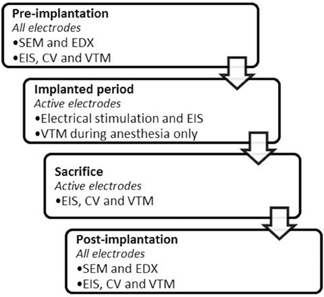
Figure 1. Timeline of the measurements performed before, during and after the implanted period.
Electrode Fabrication
The porous TiN thin films were deposited on the tip of 15 Ti6Al4V substrates (6 mm2) and 3 commercially pure Ti-discs (1000 mm2) by reactive DC magnetron sputtering using an industrial CemeCon CC800 coating unit. The sputtering chamber was equipped with two magnetrons—each mounted with a 88 × 200 mm Ti target (grade I). A continuous DC power of 2 kW was applied at each magnetron. The depositions were carried out in an Ar/N2 atmosphere, where N2 acts as the reactive gas for the TiN film formation at a total pressure of about 2900 mPa. The Ar/N2 gas flow ratio was 180 sccm/240 sccm, resulting in over-stoichiometric TiNx films. The deposition rate was 7.5 nm/min, and the films were synthesized with nominal thickness of 12.5 μm by controlling the deposition time.
Figure 2 describes the production process of the electrodes. A 35N LT wire, insulated with a thin eTFE coating (Heraeus, Switzerland) was laser welded to the end of the Ti pin and to the Ti disks. The pins used as in vivo electrodes were insulated using an injection molded MED-6033 silicone (NuSil, USA) jacket, which was glued to the pin using silicon adhesive MED2-4213 (NuSil, USA). The in vitro pins were not insulated, as this would prevent usage of a water tight electrochemical cell.
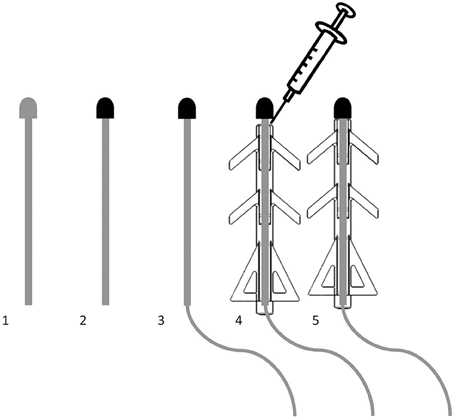
Figure 2. Fabrication of the electrodes was done in 5 steps, starting with a bare Ti6Al4V pin (1). Its tip was sputter coated with porous TiN (2). A 35N LT wire was laser welded to the pin (3). The silicone jacket was slid onto the pin and attached using a silicone adhesive (4). After curing, the electrode was finished (5).
Surgical Procedure
The electrodes were implanted in two 18 month old Göttingen minipigs. The protocol was approved by the Danish animal experiments inspectorate under license number 2012-15-2934-00177. The animals were first tranquilized and then anesthetized using a bolus injection of propofol. Anesthesia was maintained using intra-venous administration of propofol at 12 ml/h. A concentric needle was inserted into the tissue close to the vagina aiming for the genital nerve while stimulating at 1 Hz. When the threshold for eliciting a contraction of the anal sphincter was less than 5 mA using a 0.2 ms biphasic current pulse, the needle was assumed to be near the genital nerve. The electrodes were then implanted using a Seldinger-like technique. This procedure was performed on the right and left side of the vagina. The active electrodes had a percutaneous exit site at the back of the pigs. The passive electrodes were implanted subcutaneously at various positions on the back and had no percutaneous connection. One counter electrode (TiN coated Ti disk) was implanted at the back of each pig with a percutaneous connection to allow for measurements. The distance between the counter and the working electrodes was approximately 30 cm.
Electrical Measurements
A 3-electrode setup was used for the electrochemical measurements during the pre- and post-implantation measurements, consisting of a TiN working electrode, a platinum foil counter electrode (50 cm2) and an Ag|AgCl wire reference electrode (1.6 cm2). The in vitro measurements were done in an electrochemical cell where the electrodes were in a fixed position to keep the electrolyte resistance constant. During the implanted period, a TiN disk electrode (10 cm2) was used to serve as a counter and pseudo-reference electrode both in vitro and in vivo, which should ideally result in a 0 V open circuit potential. The surface area of the counter electrode was approximately 160 times larger than the surface area of the stimulation electrode to render its influence on the electrochemical measurements negligible.
EIS was used for electrochemical characterization before and after the implanted period, but also for monitoring the tissue response and electrode performance during the implanted period. EIS was performed using Solartron, Model 1294 in conjunction with 1260 Impedance/gain-phase Analyzer (Solartron Analytical, UK) with accompanying SMaRT software installed on a laptop. Table 1 shows the different measurement settings that were used during the pre- and post-implantation characterization measurements and during the implanted period (in vivo and in vitro). Three different currents were used during the characterization measurements to ensure that the measurement currents were in the linear operation range of the electrode (Ragheb and Geddes, 1990). EIS was performed on every work day during the first weeks after implantation. As the impedance spectra stabilized, the number of measurements per week was reduced. During the measurements, animals were restrained in a custom-built sling.
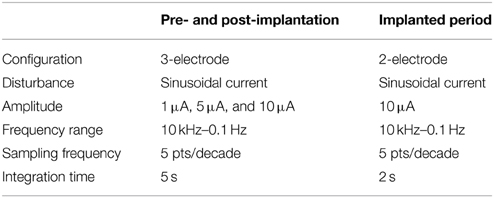
Table 1. Measurement settings for in vitro and in vivo EIS measurements.
VTM were made using a cathodic-first bipolar symmetric stimulation pulse; each with a phase width of 200 μs. Charge injection limits (Qinj) were determined using the maximal cathodic and anodic voltages from which the potential drop due to the electrolyte resistance (IR-drop) was subtracted, Emc and Ema, respectively. The IR-drop was calculated by subtracting the potential at 20 μs after pulse cessation from the last data point of the anodic phase (Cogan, 2008). To determine Qinj, the current was increased until Emcor Ema reached the water window potentials, which were −0.6 V and 0.9 V vs. Ag|AgCl in vitro and −0.403 and 1.107 V in vivo, as no reference electrode was used. For analysis of the voltage transients, the open-circuit potentials were set to 0 V, this is referred to as normalization. A current of 5 mA was used, as this was expected to be representative for a relatively high stimulation current. In vivo VTM and CV were made while the pigs were anesthetized for other purposes (CT scanning and replacing sutures).
CV was performed by cycling the electrode potential between the water window limits, which were -0.6 and 0.9 V vs. Ag|AgCl before and after the implanted period. The in vitro limits were determined beforehand using comparable electrodes. The limits used during the implanted period were based on these, though they were shifted to account for not using a reference electrode: −0.403 and 1.107 V. CV was performed at 0.05, 0.1, 0.5, 1.0, 5.0, and 10.0 V/s. The cathodic and anodic charge storage capacity (CSC) of the electrode was defined as the surface area under and over the 0 A axis, respectively. CV and VTM were performed using the VersaSTAT 3 potentio- galvanostat (Princeton applied research, USA).
Electrical stimulation was performed weekly using a Teca Synergy T-EP—EMG/EP Monitoring System (Oxford Instruments Medical, UK). The pigs were restrained using a custom built sling while stimulation was performed. The lowest current at which an anal sphincter contraction was observed visually, using a pulse train of 5 0.2 ms biphasic current pulses, was considered the threshold. Stimulation was increased to investigate whether the contractions increased in strength until side-effects occurred, such as contractions of other muscles.
Analytical Measurements
SEM (Nova 600, FEI Company, Netherlands) images of all electrodes were recorded at 150, 900, and 2500x magnification before and after the implanted period to determine whether any changes occurred on the electrodes' surface structure due to the experiments. EDX (EDAX, AMETEK, Germany) spectra were made of all electrodes before and after the implanted period to determine whether there were any changes in surface chemistry of the electrodes.
Inductively coupled plasma atomic emission spectroscopy (ICP-AES) (AMETEK Spectro Arcos, AMETEK, Germany) was used for the determination of trace elements in the Ringer solution in which the in vitro electrodes were kept. The total volume of the Ringer solution (1.2 l) was condensed to a volume of 60 ml, which was used for ICP-AES.
After the animals were euthanized, tissue samples containing the in vivo electrodes were removed and drop fixed in formalin. One active electrode, one passive electrode and the subcutaneous tissue adjacent to the counter electrode was taken from each animal. When fixed, the tissue samples were sliced and stained using hematoxylin and eosin (H&E) for histological investigation.
Statistical Analysis
The pre- and post-implantation data were statistically analyzed using SPSS. The data entered into SPSS were the cathodic CSC at 0.05 V/s, the impedance magnitude (|Z|) at 0.1 Hz, and Emc of the VTM using a current of 20 mA. The data were entered into a linear mixed model with a repeated variable (time). The dependent variables were the measurement values of each of the different measurements and the fixed factors of the mixed model were time (pre- or post), type (in vitro or in vivo) and usage (active or passive). Significance tests were performed using pairwise comparisons with Bonferroni's adjustment for multiple comparisons. Estimated marginal means (EMM) and standard errors (SE) were obtained to compare the single and combined influences of the fixed factors, while keeping the other factors of the model constant.
Results
Due to broken wires, it was impossible to complete the measurements of some electrodes. Two welds of the active in vivo electrodes broke on day 4 and day 28 after implantation. The results of these electrodes were used until the welds broke. The weld of the counter electrode of pig 2 (electrode 3 and 4) broke on day 80 and there is thus no data from electrode 3 between day 80 and 90. In vivo measurements on electrode 3 in pig 2 on the day of sacrifice (day 90) was done by surgically exposing the counter electrode. Although the broken wires were unfortunate and it limits the amount the data obtained in this study, sufficient longitudinal (over 2 months) data was obtained for 2 electrodes during the chronic phase after implantation.
Implanted Period
Figure 3 shows the impedance magnitude at 10 kHz, which is representative of the tissue impedance (Rtissue), as the phase angle approached 0 from frequencies higher than 10 Hz (Figure 4). Rtissue was relatively high on day 0, because bodily fluids may not have completely surrounded and filled the pores of the electrode. The impedance then dropped due to accumulation of fluids around the electrode (Grill and Mortimer, 1994; Williams et al., 2007), after which the tissue impedance increased due to the formation of a fibrous capsule around the electrode (Grill and Mortimer, 1994; Williams et al., 2007; Lempka et al., 2009). The increasing trend was followed by stabilization of the tissue impedance. The electrolyte impedance, measured using the in vitro electrodes, remained constant throughout the study at 226 Ω.
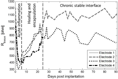
Figure 3. Rtissue of the 4 active in vivo electrodes as a function of time after implantation. There was a drop of the impedance during the first days after implantation, corresponding to the acute inflammation phase (Grill and Mortimer, 1994; Williams et al., 2007). Rtissue increased, which corresponded to healing of the tissue and encapsulation of the electrode (Grill and Mortimer, 1994; Williams et al., 2007; Lempka et al., 2009), after which Rtissue stabilized.
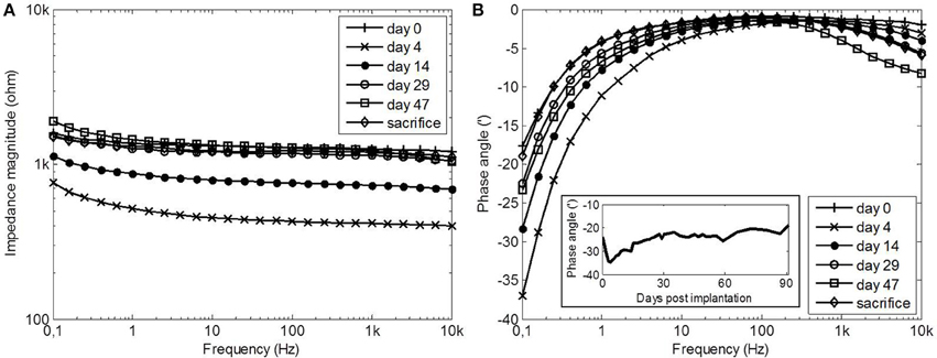
Figure 4. Impedance magnitude (A) and phase angle (B) spectra of electrode 2 at selected time points after implantation. The insert shows the average phase angle of all electrodes at 0.1 Hz as a function of time.
The impedance magnitude and phase angle spectra at selected time points are shown for electrode 2 in Figure 4. The impedance magnitude spectrum (Figure 4A) was lowest on day 4, after which it increased and stabilized at the level of day 0. The phase angle spectra (Figure 4B) showed a similar trend at the frequencies below 10 Hz (see insert). The phase angle was lowest on day 4, after which it increased to the level of day 0. The phase angle was close to zero between 10 Hz and 1 kHz during the entire implanted period. At frequencies above 1 kHz, the phase angle decreased with time. During the entire implanted period, none of the properties of the in vitro electrodes changed.
Figure 5 shows that the normalized voltage excursions of the in vivo electrodes increased with time. The increasing trend in the anodic phase of the voltage transients leveled off from day 25. For the cathodic phase the voltage transients on day 47 and day 87 had the same magnitude. No increasing trend was observed for in vitro electrodes, which had an average cathodic and anodic voltage excursion of 14 ± 2 mV and 6.5 ± 1 mV, respectively, throughout the implanted period. The average voltage excursion of the in vivo electrodes on day 0 was 13 times larger than the average voltage excursion of the in vitro electrodes. Figure 6A shows that the voltage transients of each of the electrodes were differently affected during the implanted period. The increase in the voltage excursions leveled off for electrodes 2 and 3, which had voltage excursions that were 39 and 21 times larger than those of the in vitro electrodes, respectively.
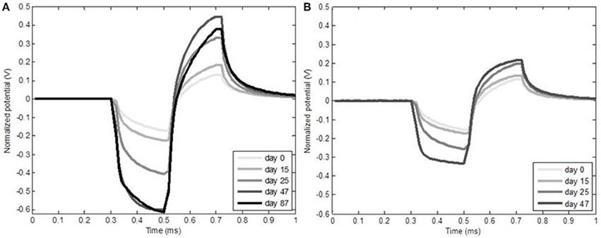
Figure 5. Normalized voltage transients of in vivo electrode 2 (A) and 3 (B) increased with time. The anodic voltage transients appeared to stop increasing from day 25. The cathodic voltage transient of electrode 2 stopped to increase from day 47. No in vivo voltage transients could be measured for electrode 3 on day 87, as the wire of the counter electrode was missing.
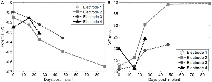
Figure 6. The ratio of the in vivo/in vitro voltage excursions (VE ratio) (A) and Emc (B) for each of active in vivo electrodes the electrodes. Especially electrode 2 and 3 were similarly but to a different extent affected during the implanted period.
Emc of the individual electrodes decreased with time (Figure 6B), due to the influence of the OCP, and the water window limit (−0.403 V) was exceeded on day 47 and 87 for electrode 2. Qinj was measured using electrode 2 and 3 in vivo after 90 days; these were 7 and 20 μC/cm2, respectively.
Figure 7A shows the CV of two implanted electrodes just before sacrifice, which was more diagonal than during in vitro measurements (Figure 7B), due to the encapsulation tissue around the electrode contact (Fjorback et al., 2006). The CSC of both in vivo electrodes was lower (98.2 and 64.8 mC/cm2) than the CSC of the in vitro electrodes (138.9 ± 6 mC/cm2) characterized at the end of the implanted period. The CSC of the in vivo electrodes was at the pre-implantation level when measured in vitro after the implanted period.
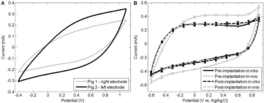
Figure 7. The in vivo CV of electrode 2 and 3 at sacrifice shows a more resistive than capacitive behavior (A). Average CV of the in vivo and in vitro electrodes pre- and post-implantation showing the capacitive behavior that is characteristic for TiN (B).
It was possible to consistently elicit a reflex contraction of the anal sphincter using electrode 2. During the first 3 weeks the threshold for eliciting a reflex was 2.5 mA, after which the threshold decreased to 1.5 mA. In pig 2 (electrodes 3 and 4), a contraction of the anal sphincter due to stimulation could not be distinguished, as rhythmic sphincter contractions also occurred without stimulation.
Pre- and Post-implanted Period
The electrodes were divided into 4 groups: active in vitro, passive in vitro, active in vivo, and passive in vivo. Measurements were made before and after the implanted period and comparisons were made before and after the implanted period between the different groups and between the pre- and post-implantation measurements within the different groups.
Before the implanted period, the in vitro electrodes had a lower |Z|, higher CSC and lower voltage excursions than the in vivo electrodes (p < < 0.05 for all measurements). The only significant difference after the implanted period was a lower |Z|of the active in vitro electrodes than the active in vivo electrodes (p = 0.02).
All electrode groups had a higher |Z|after as compared to before the implanted period (p < < 0.05) (Table 2). The post-implantation voltage excursions of the active in vitro electrodes had increased significantly (p = 0.007) as compared to before the implanted period; Emc decreased accordingly from −47 ± 7 to −72 ± 5 mV (Table 3). The voltage excursions of the passive in vivo electrodes, on the other hand, had decreased significantly (p = 0.009) after as compared to before the implanted period; Emc increased accordingly from −1.3±6 to −83 ± 4 mV (Table 3). There were no significant differences between the voltage excursions in the pre- and post-implantation measurements of the passive in vitro electrodes and the active in vivo electrodes. Furthermore, the in vitro electrodes had a significantly higher CSC before the implanted period, as compared to after (p < < 0.05) (Table 4). The surface area of the voltammogram of the in vitro electrodes was smaller after the implanted period as compared to before, but showed no qualitative changes (Figure 9B). The voltammogram of the in vivo electrodes did not show any differences before as compared to after the implanted period (Figure 9B). The CV of all electrodes, before and after implantation, became diagonal at a sweep rate of 0.5 V/s, confirming the high level of porosity of the electrodes (Cunha et al., 2009).
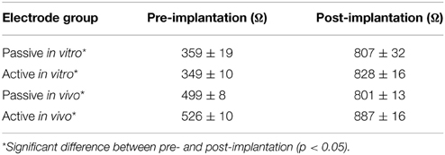
Table 2. Mean |Z| at 0.1 Hz of the different groups of electrodes before and after the implanted period (EMM ± SE).
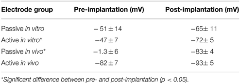
Table 3. Mean Emc of the different groups of electrodes before and after the implanted period using a 20 mA current (EMM ± SE).
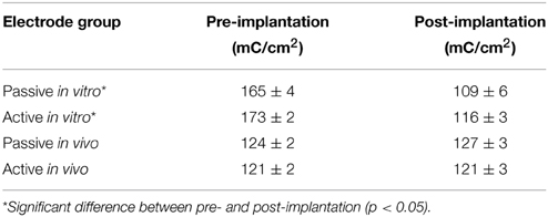
Table 4. Mean CSCC of the different groups of electrodes before and after the implanted period using a sweep rate of 0.05 V/s (EMM ± SE).
The SEM images showed no cracks or pits in the bulk electrode area and displayed an open columnar microstructure (Figure 8). However, other particles were found on the electrodes. EDX revealed that these were carbon particles and they accounted for an average of 21 wt-% (range: 5–60 wt-%). The particles could not be. removed using isopropyl alcohol, ultrasonic or electrochemical treatment. The electrodes were cleaned and sterilized before implantation and no signs of infection were found in the animals, although histology at the end of the study revealed the presence of eosinephilic granulocytes in the fibrous tissue capsule (Figure 9). SEM after explantation showed no changes in the surface structure (Figure 8), although EDX showed an increase in the amount of carbon to an average of 30 wt-%. This was due to the presence of (fixated) cells on the in vivo electrodes and remnants of Ringer salts in the pores of the in vitro electrodes. The levels of oxygen before and after the implanted period were the similar. Low levels of oxygen are typically found on TiN surfaces, as a small oxide layer is formed due to air exposure (Norlin et al., 2005; Avasarala and Haldar, 2010). No electrode particles were found in the tissue surrounding the electrodes. Neither were any TiN or silicone traces found in the ICP characterization of the Ringer solution in which the in vitro electrodes were kept during the 90 days implanted period.
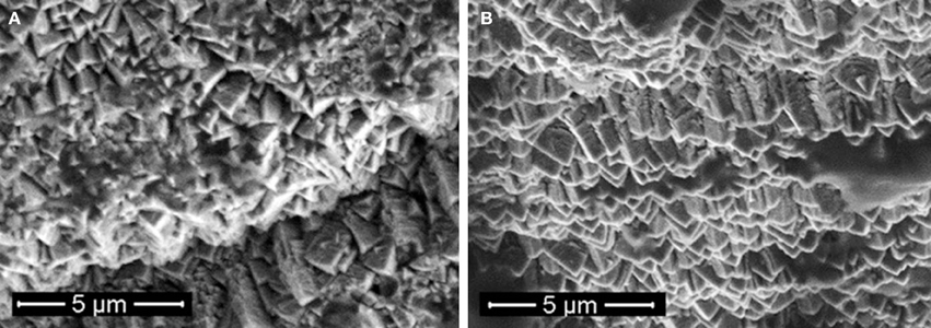
Figure 8. SEM of an active in vivo electrode before (A) and after (B) the implanted period.
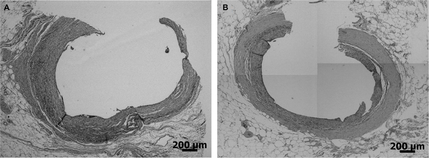
Figure 9. Histology of and active (A) and a passive (B) in vivo electrode.
Discussion
The contamination of the electrodes with carbon particles was unfortunate, but as the electrodes performed outstanding electrochemically (Weiland et al., 2002) with an electrochemical surface area of about 23 mm2 (384 times the geometrical surface area), it was decided to test the electrodes in vivo and in vitro after autoclaving them. No signs of infection were observed and the healing period compares very well to the duration found by Grill and Mortimer (1994). No carbon particles were found in the tissue and particles were still found on the electrodes after explantation. In addition, the particles covered only approximately 2% of the entire surface area of the electrodes. The extent to which the presence of these particles may have influenced the electrochemical measurements is therefore limited.
Electrode properties In vivo
Three interesting changes were observed during the in vivo measurements: (1) the large voltage excursions in vivo as compared to in vitro, (2) the increasing trend of the normalized voltage excursions in vivo, and (3) the similarity between the trends in the phase angle below 10 Hz and Rtissue. To our knowledge none of these observations have been described for TiN electrodes before.
The similar trend in Rtissue and the phase angle below 10 Hz was partly caused by the change in Rtissue. When a simplified Randles model (a parallel RC circuit and a series resistor) is assumed, the EIS spectrum (Figure 4A) displays the behavior of the capacitor and the series resistor. When the resistance of the series resistor increases, the frequency at which the capacitive behavior is visible in the spectrum decreases. This is what happens as Rtissue increases and the insert in Figure 4B shows that the average phase angle at 0.1 Hz indeed shows the same trend as Rtissue. This, however, could not explain the observed trend completely. We therefore investigated the double layer capacitance (Cdl) using the simplified Randles model. Cdl was derived from the data as follows (Wei and Grill, 2009):
Where ω is the angular frequency, Z′ is the real part of the impedance and Z″ is the imaginary part of the impedance. Figure 10 shows that Cdl follows the same trend as Rtissue, which was consistent over the entire frequency range. Cdl is on the same level as Cdl of the in vitro electrodes on day 4. The same trend was found when the data was fitted to the simplified Randles model, signifying that the total value of Cdl is affected by changes in the medium in which the electrode is immersed. A decreasing trend in electrode capacitance was also found for a deep brain stimulation electrode, which was related to the accumulation of cells around the electrode, since no changes of the electrode impedance in albumin solution were observed (Lempka et al., 2009). We suspect that this is the same for porous TiN, as both proteins and cells have been reported to adhere well to a TiN surface (Groessner-Schreiber et al., 2002). This also explains why Cdl was at the pre-implantation level after the implanted period. We have investigated smooth TiN electrodes in vivo before, where a decreasing trend in Cdl was not observed (Meijs et al., 2012). This may indicate that this trend is specific for porous TiN electrodes, as both surface chemistry and topography influence cell adhesion (Cyster et al., 2003).
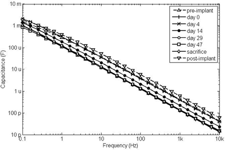
Figure 10. Cdl as a function of frequency shows a very similar trends as Rtissue. On day 0, Cdl was relatively low, whee Rtissue was relatively high. Cdl was increased on day 4, where Rtissue was decreased and Cdl decreased to day-0 value at which it remained from day 29, while Rtissue increased and stabilized during the same time course.
The in vivo voltage excursions were 13 times larger than those measured in vitro, which corresponds well to the difference in pulsing capacitance in vivo compared to in vitro. Such differences have been described for platinum micro and macro stimulation electrodes (Musa et al., 2009; Wei and Grill, 2009) and is likely due to the adsorption of proteins (Musa et al., 2009), which occurs before cells adsorb to the electrode surface (Groessner-Schreiber et al., 2002; Lempka et al., 2009). These proteins pose a diffusion limitation for the counter ions in vivo as compared to Ringer solution, which has a purely ionic content (Cogan, 2006, 2008; Lempka et al., 2009). As cells adhere to the surface the diffusion limitation increases further, causing increased impedance, IR drop and voltage excursions (Newbold et al., 2004; Gimsa et al., 2005).
The only other study to investigate charge injection of chronically implanted neural stimulation electrodes is by Kane et al. (2011, 2013). Their results (Kane et al., 2013) show decreasing values of Emc over time, which is in accordance with our findings. One major methodological difference between the study by Kane et al. (2011) and this study is the controlling of the inter-pulse potential. Therefore, Emc was not influenced by changes in the open circuit potential in their results. We attempted to achieve an open circuit potential of approximately 0 V by implanting a pseudo-reference electrode of the same material as the working electrode. The open circuit potentials deviated typically less than 40 mV from 0 V. Kane et al. (2011) used CV and EIS in vivo and attempted to determine the cause of decreasing Emc. This was inconclusive due to leakage issues (Kane et al., 2011, 2013). In the current study CV was only performed at sacrifice, where the CSC of the in vivo electrodes was 47 and 71% of their in vitro CSC before implantation. This ratio decreased with sweep rate and is likely due to the diffusion limitation posed by the tissue (Cogan, 2008; Kane et al., 2013), which is confirmed by the fact that the in vivo electrodes did not have a lower CSC post-implantation as compared to pre-implantation. The difference in CSC at the lowest sweep rate was similar to the difference found between the in vivo and in vitro values of Cdl. It must be noted, however, the safe potential limits were not determined in vivo, instead the limits used for in vitro measurement were applied in vivo. The width of the safe potential window is therefore the same in vivo and in vitro, but it is possible that the window used in vivo was too conservative (see Figure 9).
Pre- and Post-implanted Period
None of the aforementioned studies have electrochemically investigated the electrodes in vitro before and after implantation and to our knowledge this is the first study to do so. The purpose of these investigations was to determine the cause of any degradation of the electrochemical electrode properties by comparing active in vitro, passive in vitro, active in vivo, and passive in vivo electrodes. As the statistical power of this study is low, we chose to discuss only the results that were consistent for all electrodes across all measurements. With consistent is meant that a decrease in CSC was accompanied by the expected decrease in Emcand increase in |Z|. These are: (1) Before implantation the in vitro electrodes had a larger CSC, a larger Emc and lower |Z|than the in vivo electrodes. (2) After the implanted period, the in vitro electrodes had a smaller CSC, a smaller Emcand a higher |Z|than before the implanted period.
We suggest the following three theories to explain these results:
• The in vitro environment is more corrosive than the in vivo environment. This theory is supported by data from Hibbert et al. (2001) and Roblee et al. (1980). It implies that the electrochemical properties of the in vitro electrodes deteriorated during the implanted period, which is not supported by the data recorded during the implanted period. Nevertheless, the CV performed at the end of the implanted period could also have deteriorated the electrochemical properties of the in vitro electrodes (Norlin et al., 2005).
• Heterogeneity in the active in vivo electrode group. As the connection to some of the electrodes was lost quite early in the study, the group of active in vivo electrodes is rather heterogeneous. Despite the heterogeneity, the standard errors in the group of active in vivo electrodes are no different from the other electrode groups.
• Silicone adhesive had covered the edges of in vivo electrodes before the implanted period and this was removed when removing the silicone jackets. It is assumed that the electrical contacts of all electrode pins were the same before fabrication. This seems logical, as all uncoated pins came from the same batch, all pins were coated at the same time and the in vitro and in vivo electrodes were randomly chosen. It implies that all electrodes deteriorated equally during the implanted period, as there were no consistent significant differences between any of the electrode groups after the implanted period. The deterioration of the in vivo electrodes is then assumed to be concealed by the increased surface area due to removal of the silicone adhesive.
The actual explantation is likely a combination of these theories, as the first 2 fail to explain the difference between the in vitro and in vivo electrodes and the last does not give any cause for the deterioration of the electrochemical properties of the electrodes.
Implications of the Study
It is obvious from this study, that in vitro and in vivo charge injection properties cannot be compared. Attempts have been made to determine which electrolyte compares best to the in vivo situation (Cogan, 2006; Cogan et al., 2007). These studies show that the choice of electrolyte is very important, but also that the best performing electrolyte still shows significant shortcomings as compared to the in vivo data (Cogan, 2006). Comparing the electrolyte resistance to Rtissue, we find that the electrolyte resistance (226 Ω) compares well to Rtissue at its lowest level (300–500 Ω on day 2–8) with approximately double the distance between the working and counter electrode in vivo. During the acute inflammatory phase, the electrode is surrounded by bodily fluids (Grill and Mortimer, 1994; Williams et al., 2007), But as a dense capsule is formed around the electrodes (Grill and Mortimer, 1994; Williams et al., 2007; Lempka et al., 2009), even the electrolyte resistance does not resemble that of the tissue. This has been reported to influence some of the electrochemical properties of iridium oxide electrode; EIS in terms of Rtissue and the voltage transients in terms of IR drop and voltage excursions (Cogan et al., 2007). As iridium oxide electrodes inject charge via capacitive and faradic pathways (Cogan, 2006; Cogan et al., 2007), this may be different for TiN employs only capacitive pathways within the safe potential limits. We have therefore conducted some experiments with different concentrations of Ringer solution (1/4, 1/6, and 1/12-strength) and found no dependence of the voltage excursions on concentration. Adding proteins to the solution may also deteriorate the electrochemical properties of stimulation electrodes (Cyster et al., 2003; Farcas et al., 2011; Kane et al., 2011), but in the case of platinum it has a protective effect against dissolution as well (Roblee et al., 1980; Hibbert et al., 2001). The first part seems to also hold for TiN electrodes, as the impedance magnitudes and voltage transients were higher directly after implantation than before, despite the similar conductivity of the tissue and Ringer solution in the acute inflammation phase. Proteins may also have a protective effect for TiN electrodes, as most of the changes observed in vivo were reversed after explantation.
The main advantage of the electrode investigated in this study is that it can be implanted using a minimally invasive procedure, with as a drawback that this requires higher charge injection limit than with an electrode that is tied around the nerve, for example. But with the increasing voltage excursions, the question arises whether these electrodes are still good enough. The electrochemical surface area of the electrodes is 384 times larger than the surface area of a smooth electrode with the same geometrical surface area measured in Ringer solution. At the end of the implanted period, CV was performed in vivo and the CSC was decreased to 47–71% compared to their in vitro CSC. The voltage excursions, however, were more than 10 times larger in vivo compared to in vitro, which corresponded to a loss of surface area under pulsing conditions of about 93%. The voltage transient of a smooth TiN electrode in Ringer was only 4 times larger than the voltage transients of the implanted electrodes. This indicates that the electrochemical surface area of the porous electrode available under in vivo pulsing conditions is only 4 times larger than the geometrical surface area. As the voltage transients continued to increase, however, this ratio deteriorated to 1.2 for electrode 2 and thus making its performance in vivo comparable to that of smooth TiN in Ringer solution. To make a fair comparison, however, smooth and porous TiN should be tested in vivo to determine to which extent and during which phase (acute, encapsulation, or chronic) the porous electrodes are affected more than the smooth electrodes by a diffusion limitation. Based on this information, the surface structure and porosity of the coating could be tailored to increase the in vivo performance. This is necessary, as the Qinj found at the endpoint of the implanted period allows for injection of 2–6 mA, which is not enough to obtain the clinical effect in humans (Nakamura and Sakurai, 1984; Dalmose et al., 2003; Fjorback et al., 2006; Martens et al., 2011).
Additional work could also be done to better understand the difference between in vivo and in vitro voltage transients. In vivo VTM and CV could be performed more frequently during the implanted period to obtain a better understanding of the changes that occur during the implanted period and to investigate whether there is a relationship between the changing electrochemical properties of the electrodes and the encapsulation process.
Funding
This research was funded by the Danish National Advanced Technology Foundation.
Conflict of Interest Statement
The authors declare that the research was conducted in the absence of any commercial or financial relationships that could be construed as a potential conflict of interest.
Acknowledgments
The authors wish to thank the staff at the Biomedical Laboratory of Aalborg University Hospital.
References
Avasarala, B., and Haldar, P. (2010). Electrochemical oxidation behavior of titanium nitride based electrocatalysts under PEM fuel cell conditions. Electrochim. Acta 55, 9024–9034. doi: 10.1016/j.electacta.2010.08.035
Cogan, S. F. (2006). In vivo and in vitro differences in the charge-injection and electrochemical properties of iridium oxide electrodes. Annu. Int. Conf. IEEE Eng. Med. Biol. Soc. 2006, 882–885. doi: 10.1109/IEMBS.2006.259654
Cogan, S. F. (2008). Neural stimulation and recording electrodes. Annu. Rev. Biomed. Eng. 10, 275–309. doi: 10.1146/annurev.bioeng.10.061807.160518
Cogan, S. F., Troyk, P. R., Ehrlich, J., Gasbarro, C. M., and Plante, T. D. (2007). The influence of electrolyte composition on the in vitro charge-injection limits of activated iridium oxide (AIROF) stimulation electrodes. J. Neural. Eng. 4, 79–86. doi: 10.1088/1741-2560/4/2/008
Colvin, M. (2009). “An effective design process for the successful development of medical devices,” in Implantable Neural Prostheses 2, eds D. Zhou and E. Greenbaum (New York, NY: Springer-Verlag), 345–359.
Cunha, L. T., Pedrosa, P., Tavares, C. J., Alves, E., Vaz, F., and Fonseca, C. (2009). The role of composition, morphology and crystalline structure in the electrochemical behaviour of TiNx thin films for dry electrode sensor materials. Electrochem. Acta 55, 59–67. doi: 10.1016/j.electacta.2009.08.004
Cyster, L. A, Parker, K. G., Parker, T. L., and Grant, D. M. (2003). The effect of surface chemistry and nanotopography of titanium nitride (TiN) films on 3T3-L1 fibroblasts. J. Biomed. Mater. Res. A 67, 138–147. doi: 10.1002/jbm.a.10087
Dalmose, A. L., Rijkhoff, N. J. M., Kirkeby, H. J., Nohr, M., Sinkjaer, T., and Djurhuus, J. C. (2003). Conditional stimulation of the dorsal penile/clitoral nerve may increase cystometric capacity in patients with spinal cord injury. Neurourol. Urodyn. 22, 130–137. doi: 10.1002/nau.10031
Farcas, M., Cosman, N. P, Ting, D. K., Roscoe, S. G., and Omanovic, S. (2011). A comparative study of electrochemical techniques in investigating the adsorption behaviour of fibrinogen on platinum. J. Electroanal. Chem. 649, 206–218. doi: 10.1016/j.jelechem.2010.04.004
Fjorback, M. V., Rijkhoff, N., Petersen, T., Nohr, M., and Sinkjaer, T. (2006). Event driven electrical stimulation of the dorsal penile/clitoral nerve for the management of neurogenic detrusor overactivity in multiple sclerosis. Neurourol. Urodyn. 25, 349–355. doi: 10.1002/nau.20170
Gimsa, J., Habel, B., Schreiber, U., van Rienen, U., Strauss, U., and Gimsa, U. (2005). Choosing electrodes for deep brain stimulation experiments–electrochemical considerations. J. Neurosci. Methods 142, 251–265. doi: 10.1016/j.jneumeth.2004.09.001
Grill, W. M., and Mortimer, J. T. (1994). Electrical properties of implant encapsulation tissue. Ann. Biomed. Eng. 22, 23–33. doi: 10.1007/BF02368219
Groessner-Schreiber, B., Neubert, A., Müeller, W. D., Hopp, M., Griepentrog, M., and Lange, K. (2002). Fibroblast growth on surface-modified dental implants: an in vitro study. J. Biomed. Mater. Res. A 64, 591–599. doi: 10.1002/jbm.a.10417
Hibbert, D. B., Weitzer, K., and Carter, P. (2001). Voltammetry of platinum in artificial perilymph solution. J. Electrochem. Soc. 148, E1–E7. doi: 10.1149/1.1344543
Kane, S. R., Cogan, S. F., Ehrlich, J., Plante, T. D., and McCreery, D. B. (2011). Electrical performance of penetrating microelectrodes chronically implanted in cat cortex. Annu. Int. Conf. IEEE Eng. Med. Biol. Soc. 2011, 5416–5419. doi: 10.1109/iembs.2011.6091339
Kane, S. R., Cogan, S. F., Ehrlich, J., Plante, T. D., McCreery, D. B., and Troyk, P. R. (2013). Electrical performance of penetrating microelectrodes chronically implanted in cat cortex. IEEE Trans. Biomed. Eng. 60, 2153–2160. doi: 10.1109/TBME.2013.2248152
Lempka, S. F., Miocinovic, S., Johnson, M. D., Vitek, J. L., and McIntyre, C. C. (2009). In vivo impedance spectroscopy of deep brain stimulation electrodes. J. Neural Eng. 6, 1–11. doi: 10.1088/1741-2560/6/4/046001
Martens, F. M. J., Heesakkers, J. P. F. A., and Rijkhoff, N. J. M. (2011). Minimal invasive electrode implantation for conditional stimulation of the dorsal genital nerve in neurogenic detrusor overactivity. Spinal Cord 49, 566–572. doi: 10.1038/sc.2010.134
Meijs, S., Fjorback, M., and Rijkhoff, N. J. M. (2012). “Chronic electrochemical investigation of titanium nitride stimulation electrodes in vivo” in Converging clinical and engineering research on neurorehabilitation, eds J. L. Pons, D. Torricelli, and M. Pajaro (Heidelberg: Springer-Verlag), 421–425.
Merrill, D. R. (2009). “The electrochemistry of charge injection at the electrode/tissue interface,” in Implantable Neural Prostheses 2, eds D. Zhou and E. Greenbaum (New York, NY: Springer-Verlag), 85–138.
Musa, S., Welkenhuysen, M., Prodanov, D., Eberle, W., Bartic, B., Nuttin, B., et al. (2009). In vitro and in vivo electrochemical characterization of a microfabricated neural probe. Annu. Int. Conf. IEEE Eng. Med. Biol. Soc. 2009, 7143–7146. doi: 10.1109/iembs.2009.5335362
Nakamura, M., and Sakurai, T. (1984). Bladder inhibition by penile electrical stimulation. Br. J. Urol. 56, 423–415. doi: 10.1111/j.1464-410X.1984.tb05833.x
Navarro, X., Krueger, T. B., Lago, N., Micera, S., Stieglitz, T., and Dario, P. (2005). A critical review of interfaces with the peripheral nervous system for the control of neuroprostheses and hybrid bionic systems. J. Peripher. Nerv. Syst. 10, 229–258. doi: 10.1111/j.1085-9489.2005.10303.x
Newbold, C., Richardson, R., Huang, C. Q., Milojevic, D., Cowan, R., and Shepherd, R. (2004). An in vitro model for investigating impedance changes with cell growth and electrical stimulation: implications for cochlear implants. J. Neural Eng. 1, 218–227. doi: 10.1088/1741-2560/1/4/005
Norlin, A., Pan, J., and Leygraf, C. (2005). Investigation of electrochemical behavior for stimulation/sensing materials for pacemaker electrode applications: Pt, Ti, and TiN coated electrodes. J. Electrochem. Soc. 152, J7–J15. doi: 10.1149/1.1842092
Ragheb, T., and Geddes, L. A. (1990). Electrical properties of metallic electrodes. Med. Biol. Eng. Comput. 28, 182–186. doi: 10.1007/BF02441775
Roblee, L. S, McHardy, J., Marston, J. M., and Brummer, S. B. (1980). Electrical stimulation with Pt electrodes V. The effect of protein on Pt dissolution. Biomaterials 1, 135–139. doi: 10.1016/0142-9612(80)90035-6
Stieglitz, T., and Meyer, J.-U. (2006). “Neural implants in clinical practice,” in BioMEMS, ed G. A. Urban (Dordrecht: Springer-Verlag), 41–70.
Wei, X. F., and Grill, W. M. (2009). Impedance characteristics of deep brain stimulation electrodes in vitro and in vivo. J. Neural Eng. 6, 1–9. doi: 10.1088/1741-2560/6/4/046008
Weiland, J. D, Anderson, D. J., and Humayun, M. S. (2002). In vitro electrical properties for iridium oxide versus titanium nitride stimulating electrodes. IEEE Trans. Biomed. Eng. 49, 1574–1579. doi: 10.1109/TBME.2002.805487
Williams, J. C., Hippensteel, J. A., Dilgen, J., Shain, W., and Kipke, D. R. (2007). Complex impedance spectroscopy for monitoring tissue responses to inserted neural implants. J. Neural Eng. 4, 410–423. doi: 10.1088/1741-2560/4/4/007
Keywords: implantable neural prosthesis, foreign body reaction, electrical stimulation, electrochemical impedance spectroscopy, voltage transient measurements
Citation: Meijs S, Fjorback M, Jensen C, Sørensen S, Rechendorff K and Rijkhoff NJM (2015) Electrochemical properties of titanium nitride nerve stimulation electrodes: an in vitro and in vivo study. Front. Neurosci. 9:268. doi: 10.3389/fnins.2015.00268
Received: 11 June 2015; Accepted: 16 July 2015;
Published: 04 August 2015.
Edited by:
Michele Giugliano, University of Antwerp, BelgiumReviewed by:
Fabrice O. Morin, Fatronik-Tecnalia Foundation, SpainXavier Navarro, Universitat Autonoma de Barcelona, Spain
Copyright © 2015 Meijs, Fjorback, Jensen, Sørensen, Rechendorff and Rijkhoff. This is an open-access article distributed under the terms of the Creative Commons Attribution License (CC BY). The use, distribution or reproduction in other forums is permitted, provided the original author(s) or licensor are credited and that the original publication in this journal is cited, in accordance with accepted academic practice. No use, distribution or reproduction is permitted which does not comply with these terms.
*Correspondence: Suzan Meijs, SMI, Department of Health, Science and Technology, Aalborg University, Fredrik Bajersvej 7D, 9220 Aalborg, Denmark, smeijs@hst.aau.dk