 Saad Aldawood1,2*
 Ines Castelhano1,3Roman Gernhäuser4Hugh Van Der Kolff1,5Christian Lang1Silvia Liprandi1Rudolf Lutter1Ludwig Maier4Tim Marinšek1Dennis R. Schaart5
 Katia Parodi1Peter G. Thirolf1
- 1Faculty of Physics, Ludwig-Maximilians-University Munich, Munich, Germany
- 2Department of Physics and Astronomy, King Saud University, Riyadh, Saudi Arabia
- 3Faculty of Science, University of Lisbon, Lisbon, Portugal
- 4Physik Department E12, Technical University Munich, Garching, Germany
- 5Faculty of Applied Science, Radiation Science and Technology, Delft University of Technology, Delft, Netherlands
The properties of a 50 mm × 50 mm × 30 mm monolithic LaBr3:Ce scintillator crystal coupled to a position-sensitive multi-anode photomultiplier (PMT, Hamamatsu H9500), representing the absorbing detector of a Compton camera under study for online ion (proton) beam range verification in hadron therapy, was evaluated in combination with either absorptive or reflective crystal surface coating. This study covered an assessment of the energy and position-dependent energy resolution, exhibiting a factor of 2.5–3.5 improvement for the reflectively wrapped crystal at 662 keV. The spatial dependency was investigated using a collimated 137Cs source, showing a steep degradation of the energy resolution at the edges and corners of the absorptively wrapped crystal. Furthermore, the time resolution was determined to be 273 ps (FWHM) and 536 ps (FWHM) with reflective and absorptive coating, respectively, using a 60Co source. In contrast, the light spread function (LSF) of the light amplitude distribution on the PMT segments improved for the absorptively wrapped detector. Both wrapping modalities showed almost no differences in the energy-dependent photopeak detection efficiency.
1. Introduction
Particle therapy has opened a new horizon particularly for the treatment of tumors in the vicinity of critical organs at risk, due to the sharp dose localization in the Bragg peak. However, in order to fully exploit the beneficial properties of the well localized dose deposition in the tumor volume, a precise monitoring of the ion beam range is mandatory. For this purpose, an online monitoring system based on a Compton camera designed to detect prompt (multi-MeV) γ rays, induced by nuclear reactions between the ion beam and biological tissue, is being developed at LMU Munich (7, 19). This camera is composed of six customized double-sided Si-strip detectors (DSSSD), with an active area of a 50 mm × 50 mm, a thickness of 500 μm and segmentation of 128 strips on each side, acting as scatterer (tracker), while the absorber detector is formed by 50 mm × 50 mm× 30 mm monolithic LaBr3:Ce scintillator. Besides the ability of detecting the scattered photon, this camera is also able to track the Compton electron (from multi-MeV prompt photons), due to the layered structure of the scatterer detectors. This feature does not only contribute to increase the reconstruction efficiency of the camera (enabling the reconstruction of incompletely absorbed photon events), but it also enhances the sensitivity to the source position of an incident photon from a Compton cone to an arc segment (5, 19).
The favorable properties of the LaBr3:Ce scintillator material make it the preferable detector in particular for our application in medical imaging. It has a very high light yield [61000 photons/MeV (21)] with a minor non-linearity of 6% between 60 and 1275 keV (4, 17). The material density [5.06 g/cm3 (4)] and effective atomic number [Zeff = 46.9 (10)], result in a high stopping efficiency. Moreover, this detector provides an excellent energy resolution from low photon energies [~3% at 662 keV (21)] up to high energies, thus keeping the ability to resolve the full energy peak from escape peaks over a wide energy range up to about 25 MeV (3). The superior timing properties of LaBr3:Ce, due to the fast decay time of 16 ns (1) are reflected in typical time resolutions of a few hundred picoseconds (depending on the crystal dimensions). This facilitates the use of the time-of-flight (TOF) technique, e.g., to suppress neutron background or to improve the image quality as it has been reported in positron emission tomography (PET) (6, 16).
This work aims to characterize a 50 mm × 50 mm × 30 mm monolithic LaBr3:5%Ce (15) scintillator crystal, wrapped with either absorptive or (after modification by the manufacturer) reflective layer, in order to determine the optimum performance of a detector configuration to be used as an absorbing detector in a Compton camera which is presently under development for proton (ion) beam range monitoring.
2. Materials and Methods
The monolithic LaBr3:Ce scintillator (50 mm × 50 mm × 30 mm) is read out by a position-sensitive (16 × 16) multi-anode photomultiplier (PMT, Hamamatsu H9500), with 256 segments of 3 mm × 3 mm each and a coupling window of 1.5 mm thickness. The crystal was encapsulated together with the PMT in an aluminum housing, which has an entrance window of 0.5 mm thickness. The light guide (specification details are unpublished) is optically coupled between the crystal and the PMT by the manufacturer. The operational voltage of this PMT was set to be −1100 V. In order to reduce the complexity of the signal processing electronics, 4 neighboring segments with an area of 6 mm × 6 mm were combined to form 64 output channels. The detector properties, such as energy resolution, photopeak detection efficiency, time resolution, and light spread function (LSF), were evaluated.
The energy resolution was studied as a function of the γ ray energy using 152Eu (110 kBq), 60Co (32 kBq), and 137Cs (163 kBq) calibration sources, placed in an axial distance of 25 cm of the detector surface. The data was fitted using a two-parameter function expressed as
where A and B are free parameters (14). In addition, the position-dependent energy resolution was investigated by scanning the detector with a 1 mm collimated 137Cs source of 86 MBq activity and a 2 dimensional step size of 6 mm, forming 8 × 8 irradiation positions with the pencil γ ray beam pointing to the center of the respect PMT pixel group and 5 min measurement time at each position. At each irradiation position, the relative energy resolution was determined, thus generating an energy resolution map for the detector crystal with reflective and absorptive side coating, respectively. In both measurements, the evaluation of the energy resolution was based on the sum dynode signal of the PMT (Hamamatsu H9500). This signal was fed to an amplifier and Constant Fraction Discriminator (CFD) module (Mesytec, MCFD-16) and then to a VME-based Charge-to-Digital Convertor (Mesytec, MQDC-32) to enable digitized list-mode data acquisition and subsequent spectra analysis.
The photopeak detection efficiency of the LaBr3:Ce detector was evaluated using the known activities of the calibration sources. This required measuring the ratio of photons detected in the photopeak to the number of initially emitted γ rays for the specific transitions. In this case, a 152Eu source of 110 kBq activity was used in order to cover a wide range of photon energies between 121 and 1408 keV. The energy spectrum was derived from the sum dynode of the PMT. The data was corrected by background subtraction. Dead time and solid angle corrections were applied.
The timing performance of the LaBr3:Ce scintillator was investigated relative to a fast reference plastic detector (BC-418) using a coincidence method. First, the time resolution of the reference detector was determined by measuring the coincidence time between two simultaneously emitted γ rays from a 60Co source, using two identical plastic detectors (BC-418) coupled to fast PMTs (photonis XP2020/Q). The two signals of these detectors were fed to an amplifier plus CFD module (Mesytec, MCFD-16) and subsequently to a Time-to-Digital Converter (TDC, C.A.E.N. Mod. V775). Then, the time resolution of one reference detector ΔTplast.1 was extracted according to
where the ΔTplast.1+2 is the total time resolution measured by the two identical reference detectors.
Subsequently, one of the reference detectors was replaced by the LaBr3:Ce detector in order to measure the coincidence time resolution of this system. Knowing the time resolution of the reference detector and the combined time resolution (ΔTtot) of plastic and LaBr3:Ce scintillator, the time resolution of the LaBr3:Ce detector can be obtained as
Finally, the spatial resolution properties of the LaBr3:Ce scintillator was evaluated by the Light Spread Function (LSF), defined as the FWHM of the radial projection of the light distribution of the multi-anode PMT pixels. In order to extract the relevant light amplitude distributions correlated to the incident γ rays, some correction steps have to be applied consecutively:
• Gain matching: Since each channel of the 64 PMT output signals was processed by individual spectroscopic electronics, potential gain variations between channels have to be corrected. Therefore, two pulser signals with different amplitudes (50 and 100 mV) were injected to each amplifier channel in order to match the relative amplification gains of all channels.
• QDC pedestal: The charge-to-digital converter (QDC) continuously produces low-amplitude signals originating from the dark current. The intensity and energetic position of this signal varies from channel to channel. Thus, digitized data was acquired without input signal to the QDC in order to define (after applying a Gaussian fit to the pedestal peaks) a fixed pedestal subtraction threshold that was determined as 3 σ above the pedestal peak centroid.
• PMT uniformity: In order to allow for a correction of the gain variations between the 256 pixels of the multi-anode PMT (H9500), a gain non-uniformity matrix is provided by the PMT manufacturer (Hamamatsu). Since each 4 neighboring pixels of the PMT were electronically summed in this study, the corresponding gain values of the non-uniformity matrix were averaged to derive new correction factors for the 64 output channels. These relative correction factors range from 1.0 to 1.8.
• Crystal light distribution uniformity: Scattering or reflections of the scintillation light mainly in the corner or edge regions of the crystal could lead to an inhomogeneous spatial response of the crystal to impinging radiation. This can be corrected by registering the light amplitude distribution, resulting from a homogeneous flood source covering the crystal front surface, allowing to derive a correction map. Fortunately, the LaBr3:Ce crystal offers an elegant alternative. Since the internal radioactivity of the LaBr3:Ce detector (here 140 Bq, exhibiting besides distinct transitions from 138La and 227Ac (11, 18) a continuum ranging up to about 2.6 MeV) can be assumed to be homogeneously distributed inside the crystal with isotropic emission of the corresponding γ rays. The photon energy region of this background radiation equivalent to the impinging γ rays (in this case 662 keV from a 137Cs source) was used to determine the position-dependent correction matrix. This takes into account the energy dependence of the scatter/reflection processes near corners and edges of the crystal, affecting the light collection behavior.
After applying the above corrections, an 8 × 8 grid scan of the LaBr3:Ce detector using a 1-mm collimated 137Cs (86 MBq) source was performed to visualize the correlated movement of the source position. Then, one of the four central irradiation position measurements from this grid scan was selected to derive the LSF by performing a radial projection of the light amplitude distribution of the PMT pixels.
3. Results and Discussion
3.1. Energy Resolution
Figure 1 displays the energy resolution for photon energies from 121 to 1332 keV, as determined for the reflectively and absorptively coated LaBr3:Ce crystal, respectively. The dotted curves parameterize the energy dependence of the relative energy resolution according to the two-parameter function indicated in Equation (1). The relative energy resolution was found to be 12.5 and 3.5% at 662 keV for the absorptively and reflectively wrapped crystal, respectively. Throughout the energy range, the reflectively wrapped crystal exhibited a significantly improved energy resolution. In general, the energy resolution ΔE/E of a scintillation detector read out by a photomultiplier can be expressed as
where δintr is the intrinsic detector resolution affected, e.g., by crystal inhomogeneities, δtran is the transfer resolution that is correlated to the optical coupling properties of the crystal to the PMT readout, including the photocathode quantum efficiency as well as the focusing of photoelectrons to the first dynode, and δst is the statistical contribution of the PMT (12). The last two factors will determine the statistical uncertainty of the PMT, as it is directly affected by the number of photoelectrons generated at the photocathode and the photoelectron collection efficiency at the first dynode (13).
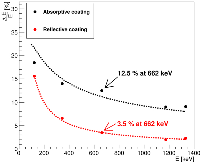
Figure 1. Energy resolution as a function of the photon energy values measured by a LaBr3:Ce detector with reflective (red) and absorptive (black) side surface coating obtained with 152Eu, 137Cs, and 60Co calibration sources. The dotted lines represent a two-parameter function fit as indicated in Equation (1).
Since the same crystal and optical coupling were used with reflective and absorptive crystal wrapping, the intrinsic term can safely be expected to give the same contributions to the overall energy resolution in both scenarios. As the generated scintillation light is partially absorbed by the absorbing wrapping material and consequently the number of the photoelectrons that reach the PMT is drastically reduced, the statistical term δst should contribute to the degradation of the energy resolution in the absorptively coated crystal, since δst is inversely proportional to the square root of the number of photoelectrons.
where vM is the variance of the PMT gain, typically between 0.1 and 0.2, and Nphe is the number of photoelectrons (12). The transfer term δtran is also expected to contribute to the energy resolution deterioration in the absorptively wrapped crystal, since in this crystal the collection of the scintillation light at the photocathode strongly depends on the interaction position at which the scintillation light is generated. This can be noticed throughout the study of the spatial dependence of the energy resolution using the 1 mm collimated 137Cs source. Moreover, even for a given position of interaction, the probability for a scintillation photon to arrive at the photocathode will depend much more strongly on the initial angle of emission than in the reflectively wrapped crystal. Figure 2 shows the resulting 2D energy resolution map of the absorptively wrapped LaBr3:Ce crystal at 662 keV. The energy resolution is gradually degrading from 8% in the central region to about 10 and 16% at the detector’s edges and corners, respectively. This can be attributed to the reduction of scintillation light reaching the PMT (thus reducing the number of photoelectrons) due to the absorption of scattered and reflected photons hitting the absorptively coated side surfaces of the scintillation crystal. This effect is much stronger for scintillation photons generated in the edge or corner regions compared to the central region of the crystal. In contrast, this effect disappears with the reflective coating of the LaBr3:Ce crystal as indicated in Figure 3. The corresponding 2D energy resolution is only slightly varying with the irradiation position, as can be seen from the respective x and y projections (averaged over the complementary dimension). An averaged relative energy resolution is achieved in this scenario. The drastic improvement by about a factor of 2.5–3.5 compared to the absorptive coating clearly emphasizes the need to preserve the full amount of scintillation light (and thus photoelectrons Nphe) via the reflective wrapping of the crystal, thus, reducing the statistical fluctuations in of Nphe at each irradiation position.
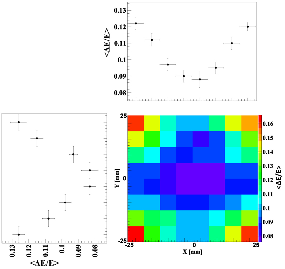
Figure 2. 2D energy resolution map together with its X and Y projection obtained by scanning the absorptively wrapped LaBr3:Ce crystal with a 1-mm collimated 137Cs source and step a size of 6 mm in x and y direction.
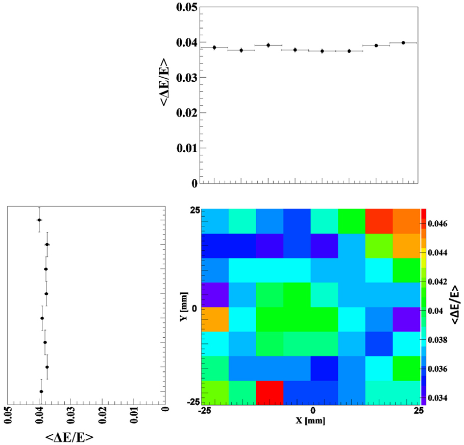
Figure 3. 2D energy resolution map measured by scanning the reflectively coated LaBr3:Ce crystal with a 1-mm collimated 137Cs source and step a size of 6 mm in x and y direction. The x and y projections (averaged over the complementary direction) show an almost position independent energy resolution of 3.8% on average.
3.2. Photopeak Efficiency
The LaBr3:Ce photopeak detection efficiency εph was determined with reflective and absorptive crystal coating over an energy range between 121 and 1408 keV, as displayed in Figure 4. With both types of crystal surface coating, the full energy detection efficiency, corrected for solid angle and data aquisition dead time, starts from high values of εph ≈ 80% at low energies (121 keV) due to the crystal thickness of 30 mm, the high effective atomic number Zeff and the density of the detector material, rendering the probability of the photoelectric interaction to be dominant in this energy region. However, the observed drop of εph with increasing photon energy correlates with the emerging dominance of multiple interactions, such as Compton scattering for high energy photons contributing to reduce the photopeak efficiency. Figure 4 also shows that the photopeak detection efficiency within experimental uncertainties is almost independent of the different surface coatings as expected.
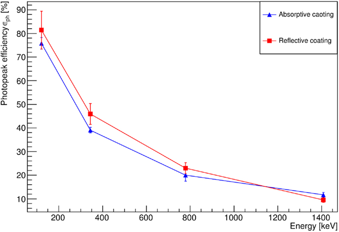
Figure 4. Photopeak detection efficiency of the absorptively (blue) and reflectively (red) wrapped LaBr3:Ce crystal using a 152Eu calibration source. Background, solid angle, and DAQ dead time corrections were applied to these data. The solid lines are to guide the eye.
3.3. Time Resolution
The timing properties of the LaBr3:Ce detector were investigated for the alternative crystal coatings relative to a fast reference plastic scintillator. Figure 5A shows the coincidence time peak of two simultaneously emitted photons from 60Co, measured by two identical plastic detectors (BC-418), exhibiting a FWHM of 365 ± 8 ps. From Equation (2), the time resolution of a single reference detector was found to be 258 ± 5 ps (FWHM). A similar result was obtained for a BC-418 scintillation detector coupled to the same PMT type (photonis XP2020/Q) by (6) to be 235 ps (FWHM). Figures 5B,C indicate 376 ± 8 ps (FWHM) and 595 ± 8 ps (FWHM) as the coincidence time measured for the reflectively and absorptively wrapped LaBr3:Ce detector, respectively, in coincidence with the reference plastic detector. Using the measured time resolution of the reference detector, the time resolution of the LaBr3:Ce detector was extracted using Equation (3) to be 536 ± 6 ps (FWHM) with absorptive and 273 ± 6 ps (FWHM) with reflective wrapping. Since the same crystal, PMT, electronics and time pick-off method were used in both side surface wrapping scenarios, the improvement in the time resolution of the LaBr3:Ce detector by more than a factor of 2 can clearly be attributed to the maximized light collection in the reflectively wrapped crystal. Consequently, the number of collected photoelectrons per event is correspondingly maximized, thus reducing the statistical fluctuations that affect the time resolution, which scales inversely proportional to the square root of the number of photoelectrons (2, 8).
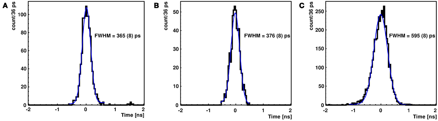
Figure 5. Time coincidence peak of two simultaneously emitted photons from 60Co measured by two identical plastic detectors (BC418) (A) and by a reflectively (B) as well as an absorptively (C) wrapped LaBr3:Ce detector measured against the reference plastic detector. The blue curve represents a Gaussian fit used to derive the indicated FWHM values.
3.4. Light Spread Function
The impact of the crystal surface coating on the position sensitivity of the LaBr3:Ce detector was studied using the 1 mm collimated 137Cs source. Figures 6 and 7 show 2D light amplitude distributions for each irradiation position on a 8 × 8 grid with 6 mm step size in x and y direction. The irradiation position is clearly correlated with the shape of the measured light distribution both with absorptive and reflective surface wrapping after applying the correction steps discussed in section 2.
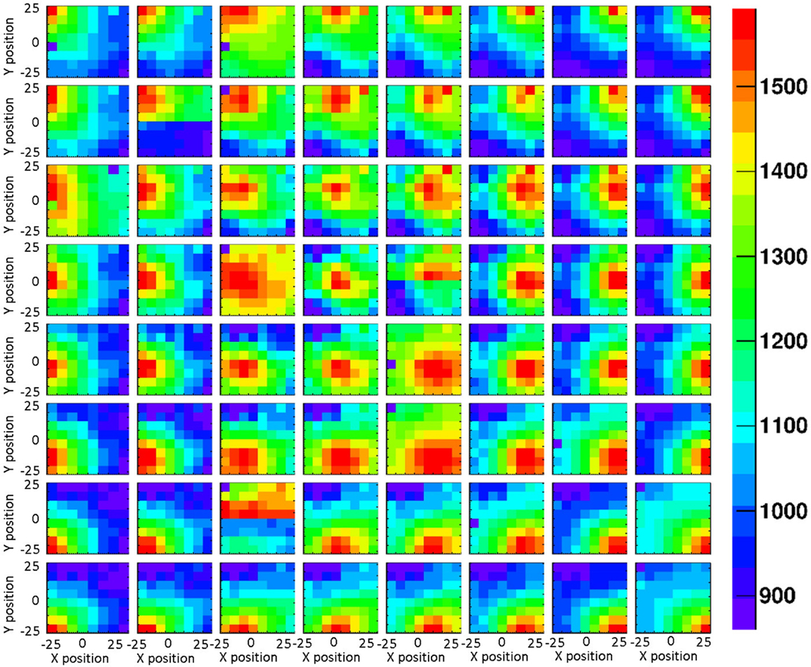
Figure 6. 2D light amplitude distribution obtained from an 8 × 8 grid scan of the absorptively wrapped LaBr3:Ce detector, using a 1 mm collimated 137Cs source with a step size of 6 mm in x and y direction. Each subpicture represents light amplitude distribution of an irradiation position. The corresponding correlation of the resulting light amplitude distributions (after the analysis steps described in Sect. 2) with the shift of the irradiation position is clearly visible.
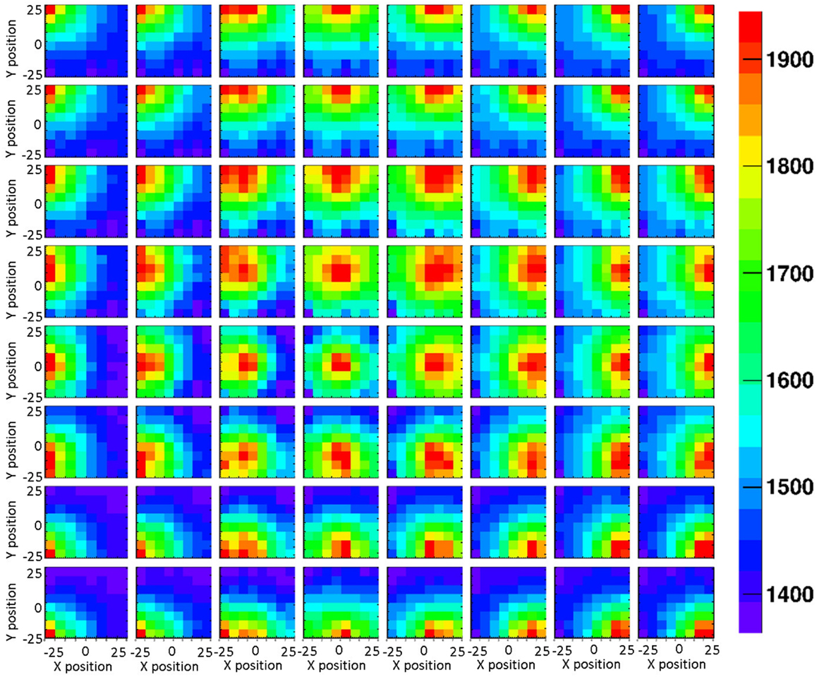
Figure 7. A grid scan of 8 × 8 irradiation positions of the reflectively coated LaBr3:Ce detector, using a 1-mm collimated 137Cs source. The source irradiation position can be clearly tracked by the intensity of the detector 2D light distribution.
The LSF, which corresponds to a radial projection of the 2D light amplitude distribution, is used to evaluate the impact of the crystal wrapping type on the detector’s spatial resolution. The absorptively wrapped LaBr3:Ce detector exhibits a LSF of 23.5 ± 4 mm FWHM (σ = 10.0 ± 1.8 mm) derived from the radial projection fit of the 2D light distribution as indicated in Figure 8. In contrast and derived from Figure 9, it was measured to be 31.7 ± 3 mm FWHM (σ = 13.5 ± 1.2 mm) for the reflectively LaBr3:Ce detector. As expected, the reflective coating degrades the position sensitivity of the detector due to the scintillation light scattering at the edges and corners of the crystal. However, this degradation does not prevent the detector from resolving the photon source-position correlation as shown in Figure 7. While so far, measurement and analysis of the LaBr3:Ce has been performed using an initial version of the signal processing electronics with 64 signal readout channels, in the further progress of the R&D project the readout electronics was upgraded to the full capacity of 256 channels needed for an individual readout of the 16 × 16 multi-anode PMT segments. Consequently, the position-dependent collimated irradiation was repeated with a finer grid step of 3 mm in x and y direction, resulting in the light amplitude correlation map shown in Figure 10, where 16 × 16 2D maps are displayed, each with 16 pixel in x and y, respectively (compared to 8 × 8 pixel in Figures 6 and 7). The higher granularity of the segmented readout and the scan stepsize enables as well a refined analysis of the LSF for the reflectively coated crystal (note that the electronics upgrade was performed after the crystal modification from absorptive to reflective coating). The resulting LSF is shown in Figure 11 exhibiting a width of 23.7 ± 0.7 mm FWHM (σ = 10.1 ± 0.3 mm), comparable to the findings for the less segmented, absorptively wrapped crystal. Based on these findings, the position information for the impinging primary photon is planned to be derived from the monolithic LaBr3:Ce scintillator using the “k-nearest neighbor” (k-NN) method developed at TU Delft (20), which requires an even finer 2D grid scan of the detector (0.5 mm collimation, 0.5 mm stepsize) (9).
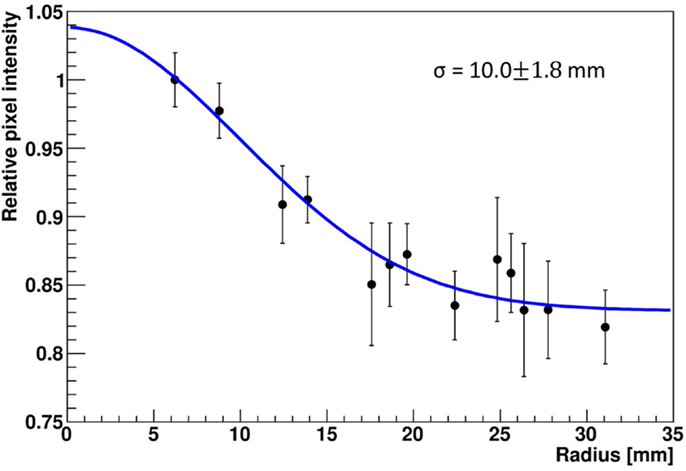
Figure 8. Radial projection of the 2D light amplitude distribution obtained from a central irradiation position of the absorptively wrapped LaBr3:Ce detector. In this study, 4 neighboring segments of the 16 × 16 multi-anode PMT were combined. The blue curve represents a Gaussian fit to the data, the resulting width σ is indicated.
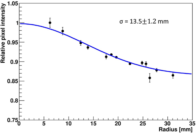
Figure 9. Radial projection of the 2D light amplitude distribution derived from a central irradiation position of the reflectively wrapped LaBr3:Ce detector. The blue curve represents a Gaussian fit to the data, the resulting width σ is indicated.
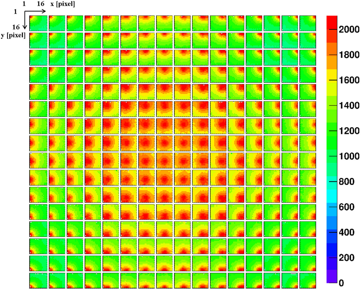
Figure 10. A grid scan of 16 × 16 irradiation positions of the reflectively coated monolithic LaBr3:Ce detector, using a 1 mm collimated 137Cs source and a grid step size of 3 mm in x and y direction. All 256 segments of the multi-anode PMT are individually read out. The resulting 2D light amplitude distribution of each irradiation position clearly indicates a systematically different pattern for the 256 different source positions.
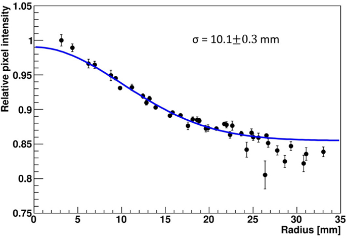
Figure 11. Radial projection of the 2D light amplitude distribution derived from a central irradiation position of the reflectively wrapped LaBr3:Ce detector coupled to a 16 × 16 multi-anode PMT. The blue curve represents a Gaussian fit to the data, the resulting width σ is indicated.
4. Conclusion
A monolithic LaBr3:Ce detector (50 mm × 50 mm × 30 mm) coupled to a position-sensitive multi-anode PMT was characterized with reflective and absorptive crystal surface coating for the purpose of optimizing the absorbing detector of a Compton camera, intended to be used as a monitoring system for ion (proton) beam range monitoring in hadron therapy. The photopeak efficiency of the detector is negligibly affected by the type of crystal coating. The reflective coating contributes to improving the energy and time resolution of the detector, because it enhances the light collection that reduces statistical fluctuations in both cases. However, this type of coating degrades the detector position sensitivity due to the increase in light scattering at the edges and corners of the crystal. While at the first glance, it appears counterproductive to use reflective side surface wrapping (plus polished crystal surface treatment) in a scenario where position resolution is targeted via a multi-anode PMT readout, in our case it is nevertheless mandatory, since an optimized energy resolution is of equal importance when operating the crystal in the context of a Compton camera. From the results obtained in this study, the reflectively wrapped LaBr3:Ce scintillator qualifies to be the optimum choice for the Compton camera absorbing detector. This is further emphasized by the presented measurements with the upgraded, highly granular electronic readout for all of the 256 PMT segments.
Author Contributions
SA: main author, acquisition, data collection, analysis, interpretation; IC, HK, CL, SL, TM: participate in experimental work and design; RG: experimental design, revising, and final approval to be published; RL: data acquisition; LM: experimental design; DS, KP, PT: interpretation, revising, and final approval to be published.
Conflict of Interest Statement
The authors declare that the research was conducted in the absence of any commercial or financial relationships that could be construed as a potential conflict of interest.
Acknowledgments
This work was supported by the DFG Cluster of Excellence MAP (Munich-Centre for Advanced Photonics) and by King Saud University, Riyadh, Saudi Arabia.
References
1. Bizarri G, de Haas J, Dorenbos P, van Eijk C. Scintillation properties of ø1x;1 inch 3 LaBr3:% 5 percent Ce3+ crystal. IEEE Trans Nucl Sci (2006) 53(2):615–9. doi:10.1109/TNS.2006.870090
2. Choong W-S. Timing resolution of scintillation-detector systems: a Monte Carlo analysis. Phys Med Biol (2009) 54(21):6495. doi:10.1088/0031-9155/54/21/004
3. Giaz A, Pellegri L, Riboldi S, Camera F, Blasi N, Boiano C, et al. Characterization of large volume 3.5 inch * 8 inch LaBr3:Ce detectors. Nucl Instr Meth A (2013) 729:910–21. doi:10.1016/j.nima.2013.07.084
4. Higgins W, Churilov A, van Loef E, Glodo J, Squillante M, Shah K. Crystal growth of large diameter LaBr3:Ce and CeBr3. J Cryst Growth (2008) 310:2085–9. doi:10.1016/j.jcrysgro.2007.12.041
5. Kanbach G, Andritschke R, Zoglauer A, Ajello M, McConnell M, Macri J, et al. Development and calibration of the tracking Compton/Pair telescope MEGA. Nucl Instr Meth A (2005) 541:310–22. doi:10.1016/j.nima.2005.01.071
6. Kuhn A, Surti S, Karp J, Raby P, Shah K, Perkins A, et al. Design of a lanthanum bromide detector for time-of-flight PET. IEEE Trans Nucl Sci (2004) 51:2550–7. doi:10.1109/TNS.2004.835777
7. Lang C, Habs D, Parodi K, Thirolf PG. Sub-millimeter nuclear medical imaging with high sensitivity in positron emission tomography using beta+gamma coincidences. J Instrum (2014) 9:P01008. doi:10.1088/1748-0221/9/01/P01008
8. Lecoq P, Auffray E, Brunner S, Hillemanns H, Jarron P, Knapitsch A, et al. Factors influencing time resolution of scintillators and ways to improve them. IEEE Trans Nucl Sci (2010) 57:2411–6. doi:10.1109/TNS.2010.2049860
9. Marinšek T. (2015). Deriving Spatial Information from a Monolithic LaBr3 Scintillator. M.Sc. thesis, Munich: LMU.
10. Mazumdar I, Gothe D, Kumar GA, Yadav N, Chavan P, Patel S. Studying the properties and response of a large volume (946 cm3) LaBr3:Ce detector with up to 22.5 MeV. Nucl Instr Meth A (2013) 705:85–92. doi:10.1016/j.nima.2012.12.093
11. Milbrath B, Choate B, Fast J, Hensley W, Kouzes R, Schweppe J. Comparison of LaBr3:Ce and NaI(Tl) scintillators for radio-isotope identification devices. Nucl Instr Meth A (2007) 572:774–84. doi:10.1016/j.nima.2006.12.003
12. Moszynski M, Zalipska J, Balcerzyk M, Kapusta M, Mengesha W, Valentine J. Intrinsic energy resolution of NaI(Tl)1. Nucl Instr Meth A (2002) 484:259–69. doi:10.1016/S0168-9002(01)01964-7
13. Pani R, Cinti M, Scaf R, Pellegrini R, Vittorini F, Bennati P, et al. Energy resolution measurements of LaBr3:Ce scintillating crystals with an ultra-high quantum efficiency photomultiplier tube. Nucl Instr Meth A (2009) 610:41–4. doi:10.1016/j.nima.2009.05.058
14. Reeder P. L., Stromswold D. C. (2004). Pacific Northwest National Laboratory report ppnl-14735. Performance of Large NaI(Tl) Gamma-Ray Detectors Over Temperature -50°C to +60°C, Available from: http://www.pnl.gov/main/publications/external/technical_reports/pnnl-14735.pdf
15. Saint-Gobain (2009). Brilliance Scintillators Performance Summary. Scintillation Products Technical Note. Available from: http://www.crystals.saint-gobain.com/uploadedFiles/SG-Crystals/Documents/Technical/SGC%20BrilLanCe%20Scintillators%20Performance%20Summary.pdf
16. Schaart DR, Seifert S, Vinke R, van Dam HT, Dendooven P, Löhner H, et al. LaBr3:Ce and SiPMs for time-of-flight PET: achieving 100 ps coincidence resolving time. Phys Med Biol (2010) 55:N179. doi:10.1088/0031-9155/55/7/N02
17. Shah K, Glodo J, Klugerman M, Moses W, Derenzo S, Weber M. LaBr3:Ce scintillators for gamma-ray spectroscopy. IEEE Trans Nucl Sci (2003) 50:2410–3. doi:10.1109/TNS.2003.820614
18. Sonzogni A. Nuclear data sheets for A = 138. Nucl Data Sheets (2003) 98(3):515–664. doi:10.1006/ndsh.2003.0004
19. Thirolf PG, Lang C, Aldawood S, Kolff HGVD, Maier L, Schaart D, et al. Development of a Compton camera for online range monitoring of laser-accelerated proton beams via prompt-gamma detection. EPJ Web Conf (2014) 66:11036. doi:10.1051/epjconf/20146611036
20. van Dam H, Seifert S, Vinke R, Dendooven P, Lohner H, Beekman F, et al. Improved nearest neighbor methods for gamma photon interaction position determination in monolithic scintillator PET detectors. IEEE Trans Nucl Sci (2011) 58:2139–47. doi:10.1109/TNS.2011.2150762
Keywords: LaBr3:Ce scintillator, γ spectroscopy, medical imaging, crystal surface coating, Compton camera
Citation: Aldawood S, Castelhano I, Gernhäuser R, Van Der Kolff H, Lang C, Liprandi S, Lutter R, Maier L, Marinšek T, Schaart DR, Parodi K and Thirolf PG (2015) Comparative Characterization Study of a LaBr3(Ce) Scintillation Crystal in Two Surface Wrapping Scenarios: Absorptive and Reflective. Front. Oncol. 5:270. doi: 10.3389/fonc.2015.00270
Received: 22 September 2015; Accepted: 19 November 2015;
Published: 07 December 2015
Edited by:
Marco Durante, GSI, GermanyReviewed by:
Yidong Yang, University of Miami Miller School of Medicine, USABilgin Kadri Aribas, A. Y. Ankara Oncology Education and Research Hospital, Turkey
Copyright: © 2015 Aldawood, Castelhano, Gernhäuser, Van Der Kolff, Lang, Liprandi, Lutter, Maier, Marinšek, Schaart, Parodi and Thirolf. This is an open-access article distributed under the terms of the Creative Commons Attribution License (CC BY). The use, distribution or reproduction in other forums is permitted, provided the original author(s) or licensor are credited and that the original publication in this journal is cited, in accordance with accepted academic practice. No use, distribution or reproduction is permitted which does not comply with these terms.
*Correspondence: Saad Aldawood, s.aldawood@physik.uni-muenchen.de