ImaSim, a software tool for basic education of medical x-ray imaging in radiotherapy and radiology
 Guillaume Landry
 François deBlois
 Frank Verhaegen
- 1Department of Radiation Oncology (MAASTRO), GROW School for Oncology and Developmental Biology, Maastricht University Medical Center, Maastricht, Netherlands
- 2Radiation Oncology Department, Jewish General Hospital, Montréal, QC, Canada
- 3Medical Physics Unit, Department of Oncology, Montréal General Hospital, McGill University, Montréal, QC, Canada
Introduction: X-ray imaging is an important part of medicine and plays a crucial role in radiotherapy. Education in this field is mostly limited to textbook teaching due to equipment restrictions. A novel simulation tool, ImaSim, for teaching the fundamentals of the x-ray imaging process based on ray-tracing is presented in this work. ImaSim is used interactively via a graphical user interface (GUI).
Materials and methods: The software package covers the main x-ray based medical modalities: planar kilovoltage (kV), planar (portal) megavoltage (MV), fan beam computed tomography (CT), and cone beam CT (CBCT) imaging. The user can modify the photon source, object to be imaged and imaging setup with three-dimensional editors. Objects are currently obtained by combining blocks with variable shapes. The imaging of three-dimensional voxelized geometries is currently not implemented, but can be added in a later release. The program follows a ray-tracing approach, ignoring photon scatter in its current implementation. Simulations of a phantom CT scan were generated in ImaSim and were compared to measured data in terms of CT number accuracy. Spatial variations in the photon fluence and mean energy from an x-ray tube caused by the heel effect were estimated from ImaSim and Monte Carlo simulations and compared.
Results: In this paper we describe ImaSim and provide two examples of its capabilities. CT numbers were found to agree within 36 Hounsfield Units (HU) for bone, which corresponds to a 2% attenuation coefficient difference. ImaSim reproduced the heel effect reasonably well when compared to Monte Carlo simulations.
Discussion: An x-ray imaging simulation tool is made available for teaching and research purposes. ImaSim provides a means to facilitate the teaching of medical x-ray imaging.
Introduction
There is a necessity to teach a range of healthcare professionals aspects of medical x-ray imaging. Engineers, medical physicists, radiologists, radiation oncologists, technologists, and many more need some degree of education in the basic physics involved with imaging.
At any level, a hands on approach coupled to classroom teaching can be beneficial to the understanding of the imaging process. Unfortunately, for most students, imaging equipment is generally monopolized by patient care, limiting the amount of time students can spend experimenting with principles learned in the classroom and their effects on image quality. Furthermore, it is often difficult to vary imaging parameters in a clinical setting since the equipment has been designed for specific purposes. Therefore, there is a clear need for a simulation environment capable of producing virtual medical x-ray images. Such a software package would serve as a useful educational tool for medical x-ray imaging.
Software packages based on simulations of x-ray imaging have been previously released: [12, 23] presented planar x-ray imaging simulation tools based on the Monte Carlo method, while [3] presented a computed tomography (CT) and cone beam CT (CBCT) simulation tool, also based on the Monte Carlo method, with calculation times in the order of hours for a single projection. Other packages have been oriented toward teaching in radiotherapy: RadSim [21] can be used to simulate the main particle interactions of interest in radiotherapy. SpekCalc [15], an x-ray spectrum calculation tool based on a verified model [16, 17], simulates x-ray production from tungsten targets in the radiology and superficial or orthovoltage therapy energy ranges.
This paper describes a novel educational tool for teaching or self-learning the basics of the x-ray imaging process, ImaSim, consisting of a teaching software package based on a simulation environment. ImaSim is highly interactive and its utilization via a graphical user interface (GUI) is intuitive. The software package covers the main x-ray based modalities: planar kilovoltage (kV), planar (portal) megavoltage (MV), fan beam CT, and CBCT imaging. The program follows a ray-tracing approach and ignores photon scatter in its current implementation, in order to reduce calculation times.
Materials and Methods
REALbasic 2009 release 5.1 (REAL Software, Inc., Austin, Texas) was used to develop and compile ImaSim. Versions of ImaSim for Windows and Mac platforms have been tested and can be downloaded along with documentation1.
Modular Approach
ImaSim was developed with a modular approach. To simplify the development as well as the learning experience, the imaging process has been broken down into a series of modules. With the aid of a GUI and three-dimensional (3D) environments, the user goes through (1) source selection, (2) object selection, (3) setup selection, (4) detector response selection and (5) image tools. Modules (1–3) have associated editors, enabling the user to create custom imaging geometries and simulation scenarios by modifying imaging parameters. These parameters are listed in Table 1. To provide the user with a sense of flow and facilitate his comprehension of the imaging process, the progression through the modules follows a series of logical steps described in Figure 1. ImaSim can be extended to account for voxelized 3D phantoms as objects to be imaged (e.g., derived from CT scans), although this is not available in the current release.
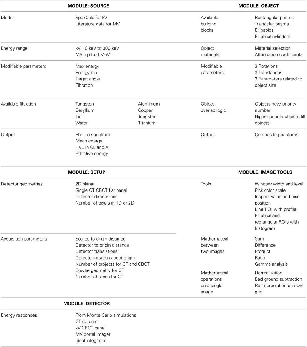
Table 1. The main imaging parameters and capabilities of ImaSim modules.
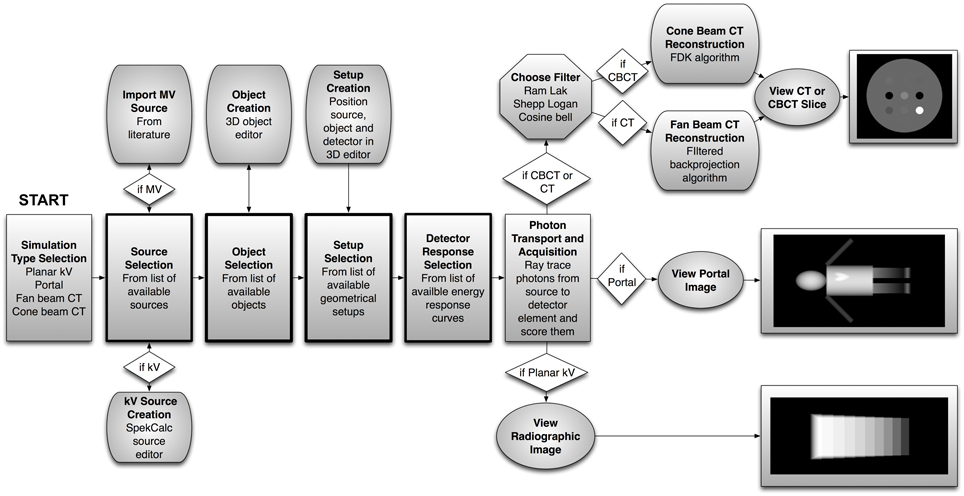
Figure 1. Flowchart representing the modules of ImaSim and the logical flow linking them. A simulation setup starts at the left with Simulation Type Selection and ends with a simulated medical image at the right. At various points in the simulation setup editors can be opened to modify relevant parameters. The core modules have thick borders. Not shown here are the image analysis capabilities of ImaSim.
The Simulation Process
Once an imaging modality has been selected (out of planar kV, CT, CBCT, and planar MV), ImaSim presents the user with the main simulation window as shown in Figure 2 for CT imaging. This window lets the user select a source, composite object, setup and detector from lists of previously created items. If no item satisfying the user's needs is available, editors can be launched to create the required item (source, object, or setup). The following sections cover modules 1-4 before explaining the underlying mechanism of image formation in ImaSim and finally covering the image tools module (5).
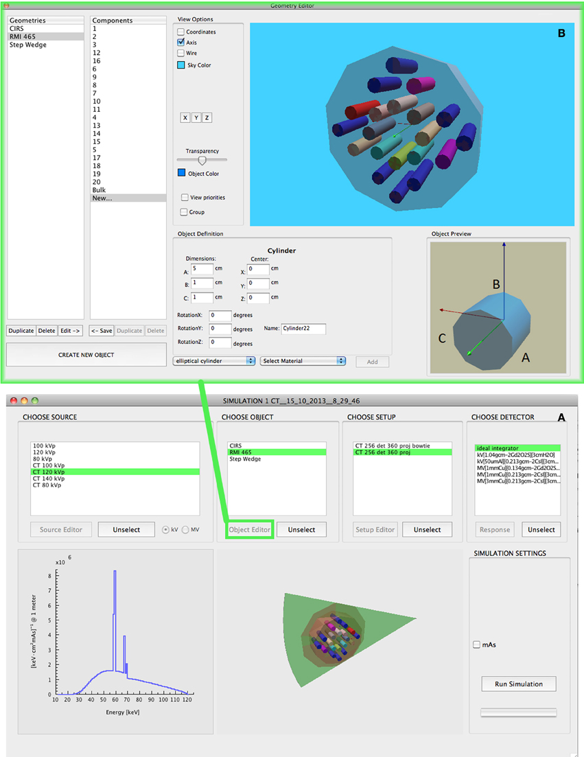
Figure 2. (A) The main simulation window of ImaSim where a source, object, setup and detector type can be selected prior to running the simulation. Shown here is a CT simulation with an arbitrary CT phantom created with the object editor. Modality specific settings such as the live acquisition of the sinogram can also be adjusted in this window. (B) Window of the Object Editor called from the simulation window showing a different composite object built from the basic building blocks. Parameters related to object material composition and size can be modified here.
Source
Two types of x-ray sources can be modeled in the software. Two megavoltage (MV) sources are selected from a library of spectra [7] and 6 MV linac spectrum from the EGSnrc distribution [9]. The library can easily be extended by the user. Custom kV sources can be created by using a modified version of SpekCalc integrated in ImaSim. This approach was chosen because a limited range of MV energies is used for verification imaging and image quality does not depend strongly on the details of the MV spectra, while for kV imaging more flexibility was allowed to reflect the wide range of applications. As the code of SpekCalc calculates the photon spectrum from an energy and depth distribution of electrons in tungsten, it was extended in ImaSim to account for the heel effect in planar x-ray imaging along the cathode anode direction. This is done, for a given position on the cathode anode axis, by calculating the target attenuation for photons from each depth bin (in the target).
Object
The user is provided with the ability to image user created custom composite objects using an editor. These are built with an object editor containing a 3D viewing environment as shown in Figure 2. Composite objects created in ImaSim are based on the building blocks listed in Table 1. A composite object consists of a combination of such building blocks. Blocks can be translated, rotated and resized. Each block has an assigned material, chosen from a total of 124 different tissue/tissue-substitute compositions. Compositions are mostly from [13, 19, 22, 24]. A few additional materials are also available, notably tissue substitutes from CIRS (Norfolk, USA, compositions from communication with CIRS). The associated photon linear attenuation coefficient data was obtained from the XCOM web database [4].
Setup
Another 3D editor, the setup editor, provides the user with the ability to position the photon source, composite object and detector in a coordinate system. Detector size and resolution as well as number of projections in CT or CBCT can also be modified with this editor. For CT a bowtie filter can be set up. The user can choose between three materials (water, PMMA, aluminium). The shape of the bowtie is calculated on the fly by first determining, for a given spectrum, the detector signal profile of a water cylinder of a user-specified radius. The mean energy of the spectrum is then used to determine the thickness of bowtie material yielding a flat detector signal profile.
Detector Response
A detector energy response can be chosen. Energy response curves govern the amount of energy absorbed in the (energy integrating) detector by incident photons. These curves vary with incident photon energy and have been pre-calculated with Monte Carlo techniques for various detector types. To obtain these responses, the Monte Carlo code GEANT4 [1] was used to determine the fraction of energy deposited by monoenergetic photons in beam geometry in layers of CsI and Gd2O2S of varying thicknesses, with varying thicknesses of aluminium or copper as covers and with 3 cm of water as backscatter.
Photon Transport and Detection
Once a source, composite object and detector have been set up and positioned in space, it is possible to simulate the acquisition of x-ray transmission data. To minimize calculation speed, the photon transport model included in ImaSim is based on ray-tracing with attenuation coefficients from the NIST XCOM database. Since objects are based on specific geometrical shapes and not voxels, the ray tracing algorithm is not currently designed to handle voxelized geometries such as CT datasets.
In a simulation, the radiological path is calculated at every pair of source points and detector elements, and for each energy in the source's spectrum. To limit calculation time, a single source point is used by default and the intensity at the central point of a detector element is calculated. For planar x-ray imaging, it is possible to sample from multiple source points to replicate focal spot blurring.
For kV sources, the user can provide the mAs. This will cause Poisson noise to be added to detector signals (from energy integrating detectors) according to the number of quanta reaching them. For MV sources noise can be added to detector signals by giving the total number of unattenuated quanta N reaching an on axis detector element. A value for N is provided by default, but the user can modify it to suit his purpose. This number is then scaled according to the detector signal (from the object-attenuated fluence) and Poisson noise is applied (using a Gaussian assumption).
Image Reconstruction
CT reconstruction is based on the filtered backprojection algorithm. To permit the use of the classical parallel beam formulation of the filtered backprojection (which is generally the formulation taught), sinograms obtained from fan beam geometries are reinterpolated to paralleled geometry following the approach of [14]. Three filters (ram-lak, shepp-logan and cosine) are implemented according to [5]. CBCT reconstruction is based on the FDK algorithm [6] with the same filter implementation as in CT.
By default, a beam hardening correction based on water attenuation properties under the selected spectrum and detector response is applied prior to reconstruction for both CT and CBCT, as well as zero-padding to the next power of two. Both these options can be turned off.
Image Tools
ImaSim provides a basic image analysis tool where quantitative data can be extracted from images. Simple operations listed in Table 1 can be performed on images. A MATLAB (MathWorks, Natick, MA) routine is also distributed with the release, which permits loading saved data and images into MATLAB.
Testing ImaSim
CT imaging
A model 002HN phantom (16 cm diameter) (CIRS Inc., Norfolk, VA) containing 5 different tissue-mimicking inserts (set 002ED from CIRS) was scanned with a second-generation dual source CT scanner (SOMATOM Definition FLASH, Siemens Healthcare, Forchheim, Germany) at 80 kVp and 140 kVp. Both spectra were generated in ImaSim following communication with Siemens regarding filtration. The scanning of the phantom was simulated and HU were compared with measurements. Simulated images were reconstructed with the cosine filter, while the measured images were reconstructed with Siemens' D26f filter.
Heel effect in x-ray tubes
To verify the validity of the treatment of the heel effect in ImaSim, a Monte Carlo simulation of an x-ray tube was performed using a BEAMnrc model [9, 18, 20]. The simulated x-ray tube consists of a tungsten target with a 25 degrees target angle. An electron beam accelerated by 140 kV with a 0.6 × 0.6 mm2 square cross section was incident on the target. The number of simulated electrons was 4 × 10⁸ and phase space files were scored at 10 cm SSD. The beam was filtered by 1 mm Al and 0.11 mm Cu.
A modified version of SpekCalc (as described at the end of section Source) included in ImaSim was used to calculate photon spectra in a detector plane situated at a 10 cm SSD. The finite focal spot was not modeled. The total number of photons normalized to unity at the center of the field and the mean energy along the cathode anode direction were derived for both Monte Carlo and ImaSim simulations.
Results
CT Imaging
Figure 3 shows CT images of the CIRS phantom obtained from measurements and simulation at 80 kVp. The quantitative comparison of HU from the measurements and simulations are presented in Table 2 for 80 kVp and 140 kVp. Good agreement between simulation and measurement was obtained, with a largest difference of 36 HU for bone at 140 kVp. This corresponds to a 2% difference of the linear attenuation coefficient. While the standard deviations of measurement and simulation have been matched by adjusting the mAs in ImaSim (5 HU in central insert), we see in Figure 3 that the noise structure from the measurement is not perfectly replicated by ImaSim. This is potentially attributable to a mismatch between the reconstruction filters used in either cases. ImaSim enables the user to explore the effect of using different reconstruction filters.
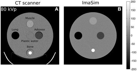
Figure 3. Comparison of measured (A) and simulated (B) CT image of the CIRS phantom at 80 kVp (HU).
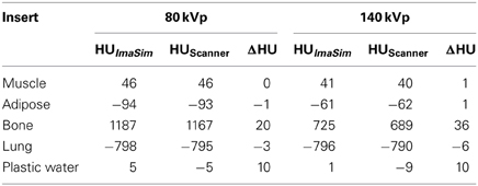
Table 2. Comparison of HU from simulation and measurement. HU are ROI-averaged.
Heel Effect in x-ray Tubes
Figure 4 presents the results of our Monte Carlo and ImaSim simulations of the heel effect. It is clearly visible with a 60% decrease of photon fluence observed by moving 2 cm from the center of the field toward the anode. The mean photon energy profiles also agree reasonably well within a few keV, with a harder spectrum found toward the field edge defined by the anode. Discrepancies could be attributable to the lack of finite focal spot size modeling in ImaSim. Comparing to Monte Carlo simulation is not a thorough validation, as effects such as anode surface roughness [8] and off focal radiation [2] could influence results of x-ray tube modeling. Keeping in mind that the intended purpose of ImaSim is educational, we can nonetheless state that the heel effect is satisfactorily modeled.
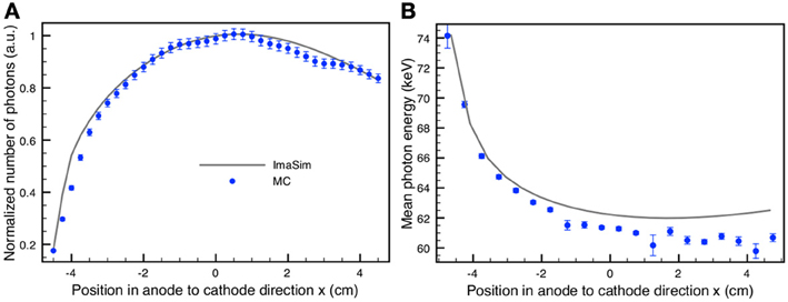
Figure 4. (A) Comparison of central photon fluence profiles along the cathode anode direction produced by Monte Carlo simulation (circles) and ImaSim (solid line). (B) Comparison of central mean photon energy profiles along the cathode anode direction produced by Monte Carlo simulation (circles) and ImaSim (solid line).
Discussion
A software package, ImaSim, containing a simulation environment for teaching and self-learning the fundamentals of medical x-ray imaging has been developed. With the aid of an intuitive GUI, image creation with the main x-ray based imaging modalities found in radiology or radiotherapy departments can be virtually explored.
ImaSim has the potential to reduce the need for hands-on experiment with expensive and heavily used equipment. Furthermore, it eliminates the risk of damaging medical equipment and provides a control over imaging parameters not found in an imaging suite.
While not initially intended for research purposes, ImaSim has been used in recently published studies to generate simulated CT images in the context of DECT imaging [10]. If the software package is to be used in a research setting, care must be taken to properly validate its results [11]. These results, and those from Figure 3 and Table 1 indicate that ImaSim should be adequate to simulate many aspects of CT imaging. This might not be the case for CBCT imaging, given the importance of scatter (not modeled) for that modality, although ImaSim could be used in the evaluation of scatter removal algorithms. The same applies to portal imaging (MV planar imaging).
The modular approach of ImaSim facilitates its expansion. Additional features such as the ability to load voxelized CT datasets are currently considered.
Author Contributions
Guillaume Landry: programming ImaSim, design of ImaSim, testing of ImaSim, writing manuscript. François deBlois: design of ImaSim, support of RealBasic as programming environment, proofreading manuscript. Frank Verhaegen: design of ImaSim, testing of ImaSim, writing manuscript, acquisition of funding to develop ImaSim.
Conflict of Interest Statement
The authors declare that the research was conducted in the absence of any commercial or financial relationships that could be construed as a potential conflict of interest.
Acknowledgments
The authors would like to thank the McGill Teaching and Learning Services (formerly the McGill Center for University Teaching and Learning) for the contributions and pedagogical support provided in the development of this project. We would also like to acknowledge the McGill Teaching and Learning Improvement Fund (MTALIF) for its financial assistance. Guillaume Landry acknowledges NSERC for funding. We wish to thank Dr. Magdalena Bazalova for technical help and Dr. Gavin Poludniowski for providing us with access to the SpekCalc code. We thank Mark Podesta, Patrick Granton, Dr. Gavin Poludniowski, and Dr. Hossein Afsharpour for their help and feedback during initial testing.
Footnotes
References
1. Agostinelli S, Allison J, Amako K, Apostolakis J, Araujo H, Arce P. Geant4-a simulation toolkit. Nucl Instrum Methods Phys Res A. (2003) 506:250–303. doi: 10.1016/S0168-9002(03)01368-8
2. Ali ES, Rogers DW. Quantifying the effect of off-focal radiation on the output of kilovoltage x-ray systems. Med Phys. (2008) 35:4149–60. doi: 10.1118/1.2966348
3. Ay MR, Zaidi H. Development and validation of MCNP4C-based Monte Carlo simulator for fan- and cone-beam x-ray CT. Phys Med Biol. (2005) 50:4863–85. doi: 10.1088/0031-9155/50/20/009
4. Berger MJ, Hubbell JH, Seltzer SM, Chang J, Coursey JS, Sukumar R. XCOM: Photon Cross Section Database version 1.3. Gaithersburg, MD: NIST (2005).
6. Feldkamp LA, Davis LC, Kress JW. Practical cone-beam algorithm. J Opt Soc Am A (1984) 1:612–9. doi: 10.1364/JOSAA.1.000612
7. Jeraj R, Mackie TR, Balog J, Olivera G, Pearson D, Kapatoes J. Radiation characteristics of helical tomotherapy. Med Phys. (2004) 31:396–404. doi: 10.1118/1.1639148
8. Kakonyi R, Erdelyi M, Szabo G. Monte Carlo simulation of the effects of anode surface roughness on x-ray spectra. Med Phys. (2010) 37:5737–45. doi: 10.1118/1.3495541
9. Kawrakow I. Accurate condensed history Monte Carlo simulation of electron transport. I. EGSnrc, the new EGS4 version. Med Phys. (2000) 27:485–98. doi: 10.1118/1.598917
10. Landry G, Granton PV, Reniers B, Ollers MC, Beaulieu L, Wildberger JE. Simulation study on potential accuracy gains from dual energy CT tissue segmentation for low-energy brachytherapy Monte Carlo dose calculations. Phys Med Biol. (2011a) 56:6257–78. doi: 10.1088/0031-9155/56/19/007
11. Landry G, Reniers B, Granton PV, van Rooijen B, Beaulieu L, Wildberger JE. Extracting atomic numbers and electron densities from a dual source dual energy CT scanner: experiments and a simulation model. Radiother Oncol. (2011b) 100:375–9. doi: 10.1016/j.radonc.2011.08.029
12. Lazos D, Bliznakova K, Kolitsi Z, Pallikarakis N. An integrated research tool for X-ray imaging simulation. Comp Methods Programs Biomed. (2003) 70:241–51. doi: 10.1016/S0169-2607(02)00015-9
13. Maughan RL, Chuba PJ, Porter AT, Ben-Josef E, Lucas DR. The elemental composition of tumors: kerma data for neutrons. Med Phys. (1997) 24:1241–4. doi: 10.1118/1.598144
14. Pan X. Optimal noise control in and fast reconstruction of fan-beam computed tomography image. Med Phys. (1999) 26:689–97. doi: 10.1118/1.598574
15. Poludniowski G, Landry G, Deblois F, Evans PM, Verhaegen F. SpekCalc: a program to calculate photon spectra from tungsten anode x-ray tubes. Phys Med Biol. (2009) 54:N433–38. doi: 10.1088/0031-9155/54/19/N01
16. Poludniowski GG. Calculation of x-ray spectra emerging from an x-ray tube. Part II. X-ray production and filtration in x-ray targets. Med Phys. (2007) 34:2175–86. doi: 10.1118/1.2734726
17. Poludniowski GG, Evans PM. Calculation of x-ray spectra emerging from an x-ray tube. Part I. electron penetration characteristics in x-ray targets. Med Phys. (2007) 34:2164–74. doi: 10.1118/1.2734725
18. Rogers DWO, Faddegon BA, Ding GX, Ma C, We J. BEAM: a Monte Carlo code to simulate radiotherapy treatment units. Med Phys. (1995) 22:503–24. doi: 10.1118/1.597552
19. Verhaegen F, Devic S. Sensitivity study for CT image use in Monte Carlo treatment planning. Phys Med Biol. (2005) 50:937–46. doi: 10.1088/0031-9155/50/5/016
20. Verhaegen F, Nahum AE, Van de Putte S, Namito Y. Monte Carlo modelling of radiotherapy kV x-ray units. Phys Med Biol. (1999) 44:1767–89. doi: 10.1088/0031-9155/44/7/315
21. Verhaegen F, Palefsky S, Deblois F. RadSim: a program to simulate individual particle interactions for educational purposes. Phys Med Biol. (2006) 51, N157–61. doi: 10.1088/0031-9155/51/8/N03
22. Watanabe Y. Derivation of linear attenuation coefficients from CT numbers for low-energy photons. Phys Med Biol. (1999) 44:2201–11. doi: 10.1088/0031-9155/44/9/308
23. Winslow M, Xu XG, Yazici B. Development of a simulator for radiographic image optimization. Computer Methods Programs Biomed. (2005) 78:179–90. doi: 10.1016/j.cmpb.2005.02.004
Keywords: education, imaging, simulation, computed tomography, x-ray
Citation: Landry G, deBlois F and Verhaegen F (2013) ImaSim, a software tool for basic education of medical x-ray imaging in radiotherapy and radiology. Front. Physics 1:22. doi: 10.3389/fphy.2013.00022
Received: 10 September 2013; Accepted: 07 November 2013;
Published online: 28 November 2013.
Edited by:
Dietmar Georg, Medical University Vienna, AustriaReviewed by:
Edite Figueiras, Tampere University of Technology, FinlandKejia Cai, University of Pennsylvania, USA
Copyright © 2013 Landry, deBlois and Verhaegen. This is an open-access article distributed under the terms of the Creative Commons Attribution License (CC BY). The use, distribution or reproduction in other forums is permitted, provided the original author(s) or licensor are credited and that the original publication in this journal is cited, in accordance with accepted academic practice. No use, distribution or reproduction is permitted which does not comply with these terms.
*Correspondence: Frank Verhaegen, Maastro Clinic, Dr. Tanslaan 12, 6229 ET, Maastricht, Netherlands e-mail: frank.verhaegen@maastro.nl