Film flow dominated simultaneous flow of two viscous incompressible fluids through a porous medium
 Olav Aursjø
 Marion Erpelding
 Ken T. Tallakstad1
  Alex Hansen
 Knut J. Måløy
- 1Department of Physics, University of Oslo, Oslo, Norway
- 2Department of Physics, Norwegian University of Science and Technology, Trondheim, Norway
We present an experimental study of two-phase flow in a quasi-two-dimensional porous medium. The two phases, a water-glycerol solution and a commercial food grade rapeseed/canola oil, having an oil to water-glycerol viscosity ratio M = 1.3, are injected simultaneously into a Hele-Shaw cell with a mono-layer of randomly distributed glass beads. The two liquids are injected into the model from alternating point inlets. Initially, the porous model is filled with the water-glycerol solution. We observe that after an initial transient state, an overall static cluster configuration is obtained. While the oil is found to create a connected system spanning cluster, a large part of the water-glycerol clusters left behind the initial invasion front is observed to remain immobile throughout the rest of the experiment. This could suggest that the water-glycerol flow-dynamics is largely dominated by film flow. The flow pathways are thus given through the dynamics of the initial invasion. This behavior is quite different from that observed in systems with large viscosity differences between the two fluids, and where compressibility plays an important part of the process.
1. Introduction
Multiphase flow in porous media is found in a wide range of fields, from fundamental research to more applied areas such as oil recovery, CO2 storage, or brewing a cup of coffee. It is seen to exhibit a broad spectrum of complex dynamics and structure formations [1–8]. This has prompted researchers to study such systems and try to understand the underlying mechanisms.
Fundamentally, any flow of immiscible fluids in a porous medium is typically dictated by the competition between viscous, capillary and gravitational forces. The interplay of these forces has, on laboratory scale, been extensively investigated using transparent quasi-two-dimensional porous media. These models render it easy to visualize and study the fluid structures obtained. Etched channel network models [9] and porous Hele-Shaw cells made up of a mono layer of beads sandwiched between two parallel plates [10, 11] have become established setups for investigating multi-phase fluid flow. The bulk of the work done has been concerned with the study of invasion processes where one fluid enters a porous medium, displacing another defending fluid initially occupying the pore space. Here, if the defending fluid is the wetting fluid the displacement is described as a drainage process. If it is the wetting fluid that invades the porous structure, the process is said to be an imbibition process. It has been shown that there exist three limiting displacement regimes for such processes [12]; capillary fingering [7, 13], viscous fingering [8, 10, 14–17], and stable displacement [5, 18, 19]. These processes have been modeled with great success by, respectively, invasion percolation (IP) [20], diffusion limited aggregation (DLA) [14], and anti-DLA [14]. Lenormand et al. [6] and Løvoll et al. [17, 21] investigated experimentally the transition regime between capillary fingering and viscous fingering. Common for all of these processes is their inherent transientness.
We investigate here a process where both fluids involved are forced to flow by the given boundary conditions. The fluids are thus forced to flow even after any transient invasion state. After a characteristic time, such systems reach a steady-state configuration where macroscopic flow parameters fluctuate around stable values. Concerned with determining relative permeability and qualitatively describing different flow regimes in this state, Payatakes and co-workers conducted extensive experimental, numerical, and theoretical studies on this type of flow [9, 22–27]. Later, Knudsen et al.[28], Knudsen and Hansen [29, 30], and Ramstad and Hansen [31] have investigated fractional flow properties and cluster formations in steady-state two-phase flow, using 2D network simulations. Tallakstad et al. [32, 33] carried out associated quasi-two-dimensional experiments, using a porous Hele-Shaw cell, obtaining a power-law relation between the measured steady-state pressure difference over the cell and the applied flow rate. In a continuation of this work, [34] investigated the history dependence of the steady-state configurations observed, by increasing and decreasing the flow rates during an experiment.
In the current study, we have investigated a system related to that of Tallakstad et al. [33]. Both studies use a water-glycerol mixture as one of the two fluid phases, but where they used air as the other phase we use a commercial food grade rapeseed/canola oil. While the air to water-glycerol viscosity ratio is ~ 10−4, the oil to water-glycerol viscosity ratio is ~ 1. This is a ratio closer to what could for instance be found under reservoir conditions during oil recovery. Replacing the air phase with a liquid phase also removes potential compressibility effects. A similar fluid pair was used by Frette et al. [18] when studying two-dimensional invasion processes with viscosity matched fluids.
The present article is organized as follows. First the experimental setup is introduced and described in Section 2. In Section 3 the results obtained from our experiments are presented and discussed. This section is divided into a description of the behavior during the transient invasion process and a part where the perpetual state behavior is discussed. The concluding remarks are given in Section 4.
2. Experimental Setup
The experimental setup consists of a horizontal transparent porous Hele-Shaw cell. A schematic representation of the experimental setup is shown in Figure 1. The porous medium consists of a monolayer of glass beads, with a diameter b = 1 mm, randomly distributed between the sticky sides of two sheets of contact paper. The porous matrix is laterally confined by a rectangular layer of silicon glue. On top of the model, a 3-cm-thick Plexiglas plate with etched flow channels allows fluids to be injected into and extracted from the porous medium. From below, a Mylar membrane, mounted on a 2.5-cm-thick Plexiglas plate and kept under pressure by a 3.5 m water column, acts as a pressurized cushion forcing the glass beads above to stay in place. The upper Plexiglas plate has 10 independent point inlets for fluid injection and one outlet channel. The distance between the inlets and the outlet channel defines the length of the porous model. The porous medium may with this be described as a rectangular box of length L = 38 cm, width W = 28 cm, and thickness b = 1.0 mm. The porosity ϕ0 and the absolute permeability κ0 of the medium are found experimentally to be ϕ0 = 0.63 and κ0 = 1.7 × 10⁻⁵ cm2, respectively. The properties of the porous medium are given in Table 1.
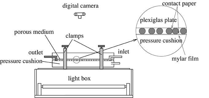
Figure 1. Schematic illustration of the experimental setup [33]. A light box illuminates the porous model from below, allowing the camera mounted above to capture sharp images of the flow structure. The porous model is sandwiched between two sheets of contact paper and kept in place with a water-filled pressure cushion and a Plexiglass plate.
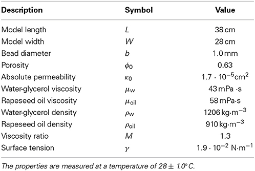
Table 1. Geometrical parameters and fluid properties in the experimental system.
We have used two liquids as our incompressible fluids. In all our experiments, the porous matrix is initially filled with a water-glycerol solution (20−80% by mass) dyed with, by mass, 0.1% Negrosine (black color). The other fluid used is a commercial food grade rapeseed/canola oil (Eldorado Rapsolje, produced in France for Norgesgruppen, Norway). The viscosities of the oil and the water-glycerol solution were measured to be μoil = 58 mPa·s and μw = 43 mPa·s, respectively. Other fluid properties are found in Table 1. The viscosity ratio is therefore M = μoil/μw ≈ 1.3. The interface tension between the two liquids was measured by using a pendant drop method [35] giving γ = 1.9 · 10−2 N/m. The system had a monitored temperature of 28 ± 1.0°C during all the experiments and measurements. With this fluid pair, it proved simple to flush the porous matrix and refill the model with the water-glycerol solution. During the flushing, any remaining oil is broken up into micro droplets which are smaller than the pore throats and, thus, are removed easily from the model.
At this point, we need to comment on some issues encountered using this type of model with this fluid pair. During the initial testing of the experiment, it was observed that the overall wetting properties of the porous material were strongly dependent on which of the two liquids the model was first exposed to in its initial “dry” state. By initially filling the “dry” model by injecting the rapeseed oil into the model, the porous medium became observably less water wet than in the case where the water-glycerol solution was used in the initial filling of the “dry” model. An observable change in the optical properties of the glass beads in the porous cell between the two situations indicates that this is due to a thin liquid film coating the beads, originating from the initial filling of the model. In this paper, we limit our investigation to the case where the water-glycerol solution coats the glass beads during the initial filling of the model. Another effect observed during the initial testing is an ageing effect of the porous model. This effect is probably also related to wetting effects. While the absolute permeability stayed unchanged over time, the level of force/pressure needed to drive a two phase flow, at a given rate, through the model increased over time. This observation encouraged us to do all the experiments in as short a time span as possible. And we were able to carry them all out over a period of 1 week. And to perform them in such an order so that any potential aging effects would give a contribution to the uncertainty/noise in the measurements rather than a monotonic drift in them. However, in our results no aging effects were observed in the time span of the experiments presented in this paper.
During the experiments the pressure in the water-glycerol phase is measured at the inlet and at the outlet of the model, using two SensorTechnics 26PC0100G6G Flow Through pressure sensors. A lightbox illuminates the model from below and the flow structure is captured at regular intervals using a Nikon D200 digital SLR camera mounted above the porous medium. This camera setup produces images of 2592 × 3872 pixels, giving a spatial resolution of about 9 × 9 pixels per mm2. The images acquired are cropped to remove boundaries, leaving images of 2208 × 3276 pixels in size to be used in the further image analysis.
As described earlier, in all the experiments the pore space of the model is initially occupied by the water-glycerol solution. The experiment is started by injecting the oil and the water-glycerol solution simultaneously from every other one of the ten inlet points on the injection side of the model. The boundary condition of the injection side may be said to be anti-symmetric around the center point on the line of inlets. This means that the two outermost inlets located at opposite ends of the injection boundary, adjacent to the side boundaries, inject opposite fluids. This results in different boundary effects on the two sides. However, most of these boundary effects are not taken into account in the image analysis, due to the cropping of the images described above.
The oil and the water-glycerol solution are injected from individual syringes connected to the individual inlet points. The five oil filled syringes and the five water-glycerol filled syringes are connected to two separate WPI ALADDIN6-220 syringe pumps that handle five syringes each. Having two separate pumps, one for each fluid phase, allows us to set different injection rates for the two phases.
3. Results
We choose to define a capillary number of the flow on pore scale, using Darcy's law, as
where μ = (μw + μoil)/2 is an average of the two viscosities, A = Wb is the cross-sectional area, and the total injection rate
Here Q0w and Q0oil are respectively the injection rates of the individual water-glycerol solution filled syringes and oil-filled syringes. In our experiments only the individual flow rates have been varied in order to vary the capillary number. All other parameters have been kept constant. Table 2 shows the 8 different total flow rates we probed in our experiments, along with the corresponding legend numbers in the following graphs.
Table 2. Total flow rates Qtot and capillary numbers Ca corresponding to the legend numbers presented in the forthcoming graphs.
We may define an oil fractional flow rate Foil = Qoil/Qtot. For each total flow rate Qtot, we carried out a set of three independent experiments where the oil fractional flow rates were put to Foil = 1/3, 1/2, or 2/3.
The rapeseed oil initially enters the porous matrix to form individual fingers originating from oil inlet points. As the invasion structure evolves, these fingers are observed to merge with one another to form a connected invasion front. The time evolution of the flow pattern for a typical experiment is shown in Figure 2. Contrary to what is found in equivalent experiments with air and a water-glycerol solution as the two fluid phases [32], the invading non-wetting phase stays connected to the inlets through the whole of the invasion process. As the initial oil fingers merge, the water-glycerol phase is seemingly fragmented into disconnected clusters. However, it is observed that these clusters are overall left static in a fixed cluster configuration behind the front. A comparison of the two lower images in Figure 2, readily demonstrates this characteristic behavior of the fluid paths in the system. Such an overall static path structure indicates that the main fluid transport of water-glycerol solution occurs as film flow in regions where a fluid phase is seemingly disconnected. This again, implies that even the water-glycerol phase stays connected.
Figure 2. For Qtot = 0.3 ml/min and Foil = 1/2, the flow structure is shown at four different times. The flow direction is from left to right. The images are ordered, from the top, by increasing time. The images are respectively captured at 68, 142, 228, and 330 min into the experiment. The two lower images show flow patterns, at steady state, with a large separtation in time.
3.1. Transient Behavior
As described above, almost all observable dynamics in the pattern structure occurs during the initial invasion before the system reaches a steady/stationary state. In the same manner as Tallakstad et al. [32], we define a characteristic steady state time tss that signals the end of the transient regime and the onset of the perpetual state (see the plot for Foil = 2/3 in Figure 5). Figure 3 accentuates what part of the process displays most of the dynamics. The graph shows how much the pattern configuration has changed between two consecutive images taken during the experiment. Here a lower threshold value for changes in the gray level value has been introduced. It is easily seen that the percentage of change observed in the fluid structure drops rapidly to a negligible level around the time of onset of steady state. This means that there are no cluster/pattern changes during the last part of the experiment. Though the experiment with the highest flow rate demonstrates a similar behavior, the fluid pattern continues to show changes also after the initial invasion. This means that there are here some minute cluster dynamics also during steady state.
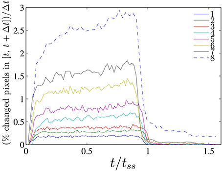
Figure 3. Time evolution of the dynamics in the invasion structures in the system. Eight independent experiments with the fractional flow rates fixed to Foil = 1/2. See Table 2 for total flow rates. The graphs show percentage change in the pattern configuration between two consecutive images taken during the experiment, per time. Here Δt represents the time interval between two consecutive images and this differ for experiments with different flow rates.
Figure 4 shows, on the top left, an image of the invasion pattern at a randomly chosen time during the initial transient state together with, on the top right, a plot showing the areas where changes have occurred in the structure since the previous image in the time series was captured. It is observed that virtually all of the minute changes that substantiate the dynamics of this system are located in the vicinity of the invasion front. The lower graph in Figure 4 shows the average position 〈y〉 of the changes observed in the structure as a function of time. The graph also includes the standard deviation σy in the position. From this, we see that during the initial invasion most of the dynamics or structural changes occur in a region close to the invasion front. After the onset of steady-state, where we have seen in Figure 4 that any dynamics has virtually vanished, the standard deviation σy shown in Figure 4 tends to increase. The few changes occuring are, i.e., not found in a localized area, but are rather scattered over more of the system.
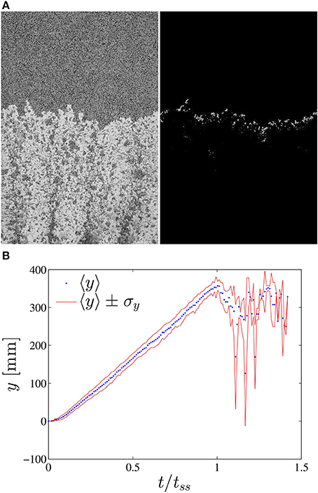
Figure 4. (A) For Qtot = 1.2 ml/min and Foil = 1/2, the invasion pattern at a chosen time during the initial transient state is shown on the left. Here, the flow direction is from the bottom to the top. On the right, the corresponding changes that have occured in the structure since the previous image in the time series, is shown. Here, the areas that are changed are marked as white, while the unchanged areas are black. (B) The mean position 〈y〉 of the changes, from the bottom end of the image (inlet side), is given as a function of the time relative to the steady-state time tss, accompanied by the standard deviation σy in the position of changed points.
3.2. Stationary State
As the system leaves the initial state of invasion and enters the perpetual stationary state of the system, the pressure difference across the model, which has been increasing steadily from the onset of invasion, levels off at a constant value (See Figure 5). In the same manner as described by Tallakstad et al. [32], the stationary state may globally be quantized by the pressure drop between the inlet and the outlet,
where tend is the end time of the experiment. In Figure 6 the average steady-state pressure differences are plotted as a function of the capillary number for the three different oil fractional flow rates investigated. We observe that ΔPss potentially exhibits the behavior of a power law in the total flow rate Qtot,
with exponents β1/2, 2/3 = 0.67 ± 0.05 for Foil = 1/2 and 2/3, and debatably a higher β1/3 = 0.74 ± 0.05 for Foil = 1/3. Here the errors are obtained from the estimated limits of power laws fitted to the data sets. The values for β found here are higher than the exponent value reported by Tallakstad et al. [32] in a system with a large viscosity difference between the two fluids. As described in the previous section the overall cluster configuration is left static after onset of the perpetual state. Only minute changes may be detected (See Figures 3, 4 for t/tss > 1). And as already stated in the beginning of this section, this indicates that both fluids flow in connected pathways from inlet to outlet. The fact that both fluids must to some extent be flowing side by side, is in agreement with the higher power law exponents observed above. In a pure Darcy type flow, the pressure difference across the model increases linearly with the applied flow rate. In our system this would correspond to a power exponent β = 1. The more the dynamics of the flow involves fluid interface dynamics, the more the flow behavior will deviate from a Darcy flow behavior. Tallakstad et al. [32] reported a more stable migration of independent air clusters through the system in the perpetual state. This corresponds to a larger degree of dynamics due to movement of fluid interfaces than what is observed in the stationary perpetual state of our system. This is in agreement with a larger divergence away from a pure Darcy type flow.
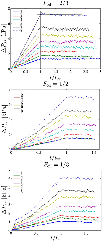
Figure 5. Time evolution of the pressure difference across the length of the model for all the experiments. Results for each given fractional oil flow rate, Foil, are here plotted together. See Table 2 for total flow rates for the individual experiments. (The undulations in the pressure plots are an unwanted signature of one of the syringe pumps used).
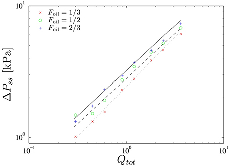
Figure 6. Average steady-state pressure difference ΔPss as a function of the total flow rate Qtot.
Figure 7 shows the steady-state two-phase-flow structure for a selection of separate experiments. With regards to the possible difference observed in the power law exponent between Foil = 1/3 and the other two oil fractional flow rates, there is from Figure 7 observably a higher degree of water-glycerol channel flow in the Foil = 1/3 experiments. This is especially prominent comparing the three rightmost images in Figure 7. There is also less interface dynamics in the experiments where Foil = 1/3. This is in agreement with a higher value for β, a value approaching 1.
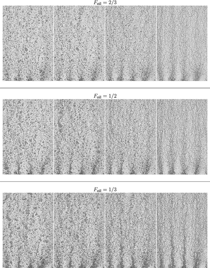
Figure 7. Steady-state fluid configurations for 12 separate experiments. Each row of images shows the fluid configurations for, from left to right, the total flow rates Qtot = 0.30, 0.60, 1.2, 3.6 ml/min. The top, middle, and bottom rows show the configurations when the fractional oil flow rate is Foil = 2/3, Foil = 1/2, and Foil = 1/3, respectively.
In a perfect two dimensional geometry, where the pore space is connected and therefore, by necessity, the solid structure is disconnected, having both phases flow in connected structures would only be possible if the two fluids flow in channels alongside each other, unsupported by film flow along the solids. From the 2D projection of our system, we observe that the water-glycerol phase appears as static disconnected clusters. This means that at least the water-glycerol phase must in some regions of the system be flowing as out-of-plane film flow. Thus, we have flow dynamics dominated by three-dimensional effects.
3.3. Water-Glycerol Cluster Size Distributions
After the systems have reached their stationary state, we have extracted the size distributions of the seemingly disconnected water-glycerol clusters stuck in the porous medium. It should be pointed out that these distributions cannot be directly compared to those found by Tallakstad et al. [32]. In their investigation, it was the distribution of clusters of air, and not water-glycerol, that was analyzed. To minimize boundary effects in the distributions extracted, all clusters connected to the boundaries of the images used, have been removed in the analysis process. The normalized probability density functions (PDF) P(s) for all total and fractional flow rates probed are presented in Figure 8. We have here, as in percolation theory [36], assumed that the normalized cluster size distribution behaves as a PDF
where s* is a statistical cutoff cluster size. Using a proportionality constant, τ, and s* as our three fit parameters, we have fitted this function to the data for each individual experiment. Due to the lack of statistics for the largest clusters of the systems, we have in the fitting procedure disregarded the data from these. For each fractional flow rate, by averaging the fitted τ exponents for the 8 individual total flow rates (given in Table 2), it is found that τ2/3 = 1.37 ± 0.09, τ1/2 = 1.43 ± 0.06, and τ1/3 = 1.48 ± 0.04, for Foil = 2/3, 1/2, and 1/3, respectively. Here, the uncertainties only reflect the differences in the exponents fitted to each individual distribution. Along with the fitted values of s*, these average values for τ were used to produce the data collapses shown in Figure 8. From this figure, we observe that the cluster size distributions exhibit a power law behavior over more than three decades.
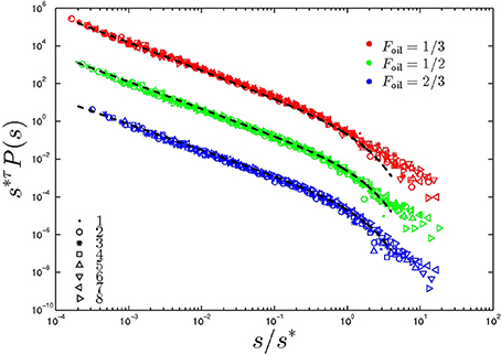
Figure 8. Data collapse of the water-glycrol cluster size distributions for all the experiments. The plots are grouped by fractional oil flow rate Foil. For each fractional flow rate, the distributions for the different Qtot are represented by differently shaped symbols. (See Table 2 for the corresponding total flow rates.) The data sets showing the cluster size distributions obtained for Foil = 1/2 have in this graph been shifted along the vertical axis by a factor of 10−2, while the distributions obtained for Foil = 1/2 have been shifted by a factor of 10−4. To produce the data collapses the fitted values of s* for each individual data set have been used, along with the average values for τ1/3 = 1.48, τ1/2 = 1.43, and τ1/3 = 1.37, for the respective fractional oil flow rates. The same values for τ were used to produce the black dotted lines which are proportional to (s/s*)−τ exp (s/s*).
With regards to the cutoff cluster size, the fitted values of s* are observed to potentially scale with the total flow rate Qtot as
Figure 9 shows s* for the three fractional flow rates as functions of the the total flow rate Qtot. By fitting the proposed function above to these sets of s*, having the proportionality constant and ζ as fit parameters, we find that ζ2/3 = 0.89 ± 0.08, ζ1/2 = 0.67 ± 0.05, and ζ1/3 = 0.51 ± 0.05, for Foil = 2/3, 1/2, and 1/3, respectively. Here, the errors correspond to the standard deviations from the fitting procedure. From this, we see a trend of possibly larger values of ζ at larger fractional oil flow rates. This would mean that the decrease in the cutoff cluster size s*, with a given increase in the total flow rate, depends on the fractional oil flow rate in the system. From Figure 9 we also observe that, for the flow rates probed, increasing the fractional oil flow rate while maintaining the total flow rate leads to a decrease in the cutoff cluster size. This might be attributed to the increased drag the water glycerol phase experiences when the oil flow rate is increased.
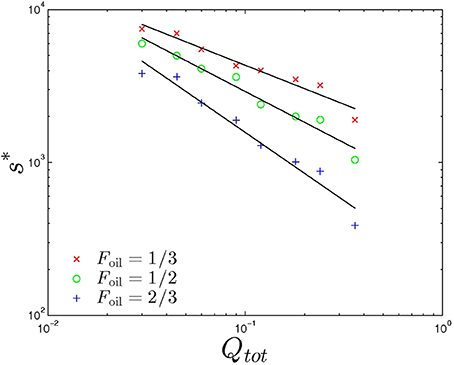
Figure 9. The fitted values of the cutoff cluster size s* for the three fractional oil flow Foil are plotted as functions of the total flow rate Qtot. The solid lines show the fitted functions proportional to Q−ζtot, where ζ2/3 = 0.89, ζ1/2 = 0.67, and ζ1/3 = 0.51 have been used for Foil = 2/3, 1/2, and 1/3, respectively.
4. Conclusion
In this paper we have experimentally studied a simultaneous incompressible two-phase fluid flow in a quasi-two-dimensional porous medium. The viscosity ratio between the two fluids was M ~ 1.3. During the experiments the flow rates of the two fluids were varied, while the other system parameters were kept constant. Both the transient and the final perpetual states observed in this system were investigated.
For most of the flow rates probed, the system behavior is observed to be dominated by the transient state dynamics. The transient state, characterized by the propagation of an invasion front, typically exhibits cluster dynamics strongly restricted to an area close to the moving invasion front. We observe that water-glycerol clusters, that are left behind by the invasion front, to a large degree stay static after they are visually disconnected from the front. This leaves the system in a perpetual stationary state. As the front propagates through the system, the pressure drop over the model, from the inlet to the outlet, is observed to increase until it levels off to a constant value in the perpetual state. It was observed that this pressure difference potentially increases as a power law with an increase in the flow rates applied. The power law exponents β extracted for the different fractional flow rates are found to be higher than what was observed by Tallakstad et al. [32, 33]. This may be put in connection with having less cluster and interface dynamics in our system.
In the stationary state, the cluster size distribution of the static water-glycerol clusters were extracted. These distributions followed a power law with a cutoff for large cluster sizes. By fitting a power law with an exponential tail to the data set there were indications that the power law exponent could be weakly dependent of the fractional oil flow rate. The data could indicate a trend where a larger fractional oil flow rate would give a slightly lower power law exponent τ than for smaller fractional oil flow rates. But these findings are not conclusive. The cutoff cluster sizes s* extracted from the cluster size distributions, however, were found to be more strongly dependent on the fractional oil flow rate.
Author Contributions
Ken T. Tallakstad, Knut J. Måløy, and Olav Aursjø designed the experiments. Ken T. Tallakstad, Marion Erpelding, and Olav Aursjø conducted the experiments. Marion Erpelding and Olav Aursjø performed the data analysis, while all the authors contributed in the discussion of the results. Olav Aursjø wrote the initial manuscript and Marion Erpelding, Ken T. Tallakstad, Eirik G. Flekkøy, Alex Hansen, and Knut J. Måløy all contributed and took part in the discussion toward finalizing the manuscript.
Conflict of Interest Statement
The Reviewer Dr. Renaud Toussaint declares that, despite having collaborated with authors Knut J. Måløy and Ken T. Tallakstad, the review process was handled objectively. The authors declare that the research was conducted in the absence of any commercial or financial relationships that could be construed as a potential conflict of interest.
Acknowledgments
The work was supported by The Norwegian Research Council, through the projects CLIMIT no. 200041, PETROMAKS no. 193298, and RENENERGI no. 217413. We thank Mihailo Jankov for assistance in the lab.
References
1. Bear J. Dynamics of Fluids in Porous Media. New York, NY: American Elsevier Publishing Company (1972).
2. Dullien FAL. Porous Media Fluid Transport and Pore Structure. 2nd Edn. San Diego, CA: Academic Press, Inc. (1992).
3. Sahimi M. Flow phenomena in rocks: from continuum models to fractals, percolation cellular automata, and simulated annealing. Rev Mod Phys. (1993) 65:1393–534. doi: 10.1103/RevModPhys.65.1393
4. Sahimi M. Flow and Transport in Porous Media and Fractured Rock. Weinheim: VCH Verlagsgesellschaft mbH (1995).
5. Lenormand R, Zarcone C, Sarr A. Mechanism of the displacement of one fluid by another in a network of capillary ducts. J Fluid Mech. (1983) 135:337–53. doi: 10.1017/S0022112083003110
6. Lenormand R, Touboul E, Zarcone C. Numerical models and experiments on immiscible displacements in porous media. J Fluid Mech. (1988) 189:165–87. doi: 10.1017/S0022112088000953
7. Lenormand R, Zarcone C. Capillary fingering: percolation and fractal dimension. Trans. in Porous Media (1989) 4:599–612. doi: 10.1007/BF00223630
8. Saffman PG, Taylor G. The penetration of a fluid into a porous medium or Hele-Shaw cell containing a more viscous liquid. Proc R Soc A (1958) 245:312–29.
9. Avraam DG, Payatakes, AC. Flow regimes and relative permeabilities during steady-state two-phase flow in porous media. J Fluid Mech. (1995) 293:207–36. doi: 10.1017/S0022112095001698
10. Måløy KJ, Feder J, Jøssang T. Viscous fingering fractals in porous media. Phys Rev Lett. (1985) 55:2688–91. doi: 10.1103/PhysRevLett.55.2688
Pubmed Abstract | Pubmed Full Text | CrossRef Full Text | Google Scholar
11. Birovljev A, Wagner G, Meakin P, Feder J, Jøssang T. Migration and fragmentation of invasion percolation clusters in two-dimensional porous media. Phys Rev E (1995) 51:5911–5. doi: 10.1103/PhysRevE.51.5911
Pubmed Abstract | Pubmed Full Text | CrossRef Full Text | Google Scholar
12. Lenormand R. Flow through porous media: limits of fractal patterns. Proc R Soc Lond A (1989) 423:159–68. doi: 10.1098/rspa.1989.0048
13. Lenormand R, Zarcone C. Invasion percolation in an etched network: measurement of a fractal dimension. Phys Rev Lett. (1985) 54:2226–9. doi: 10.1103/PhysRevLett.54.2226
Pubmed Abstract | Pubmed Full Text | CrossRef Full Text | Google Scholar
14. Paterson L. Diffusion-limited aggregation and two-fluid displacements in porous media. Phys Rev Lett. (1984) 52:1621–4. doi: 10.1103/PhysRevLett.52.1621
15. Stokes JP, Weitz DA, Gollub JP, Dougherty A, Robbins MO, Chaikin PM, et al. Interface stability of immiscible displacement in a porous medium. Phys Rev Lett. (1986) 57:1718–21. doi: 10.1103/PhysRevLett.57.1718
Pubmed Abstract | Pubmed Full Text | CrossRef Full Text | Google Scholar
16. Weitz DA, Stokes JP, Ball RC, Kushnick AP. Dynamic capillary-pressure in porous media - origin of the viscous fingering length scale. Phys Rev Lett. (1987) 59:2967–70. doi: 10.1103/PhysRevLett.59.2967
Pubmed Abstract | Pubmed Full Text | CrossRef Full Text | Google Scholar
17. Løvoll G, Meheust Y, Toussaint R, Schmittbuhl J, Måløy KJ. Growth activity during fingering in a porous Hele-Shaw cell. Phys Rev E (2004) 70:026301. doi: 10.1103/PhysRevE.70.026301
Pubmed Abstract | Pubmed Full Text | CrossRef Full Text | Google Scholar
18. Frette OI, Måløy KJ, Schmittbuhl J, Hansen A. Immiscible displacement of viscosity-matched fluids in two-dimensional porous media. Phys Rev E (1997) 55:2969–75. doi: 10.1103/PhysRevE.55.2969
19. Meheust Y, Løvoll G, Måløy KJ, Schmittbuhl J. Interface scaling in a 2d porous medium under combined viscous, gravity and capillary effects. Phys Rev E (2002) 66:051603. doi: 10.1103/PhysRevE.66.051603
Pubmed Abstract | Pubmed Full Text | CrossRef Full Text | Google Scholar
20. Wilkinson D, Willemsen JF. Invasion percolation: a new form of percolation theory. J Phys A (1983) 16:3365–76. doi: 10.1088/0305-4470/16/14/028
21. Løvoll G, Jankov M, Måløy KJ, Toussaint R, Schmittbuhl J, Schäfer G, et al. Influence of viscous fingering on dynamic saturationPressure curves in porous media. Trans. Porous Media (2011) 86:305–24. doi: 10.1007/s11242-010-9622-8
22. Avraam DG, Payatakes AC. Generalized relative permeability coefficients during steady-state two-phase flow in porous media, and correlation with the flow mechanisms. Trans. Porous Media (1995) 20:135–68. doi: 10.1007/BF00616928
23. Avraam DG, Payatakes AC. Flow mechanisms, relative permeabilities, and coupling effects in steady-state two-phase flow through porous media. The case of strong wettability. Ind Eng Chem Res. (1999) 38:778–86. doi: 10.1021/ie980404o
24. Constantinides GN, Payatakes AC. A theoretical model of collision and coalescence of ganglia in porous media. J Coll Inter. Sci. (1991) 141:486–504.
25. Constantinides GN, Payatakes AC. Network simulation of steady-state two-phase flow in consolidated porous media. AIChE J (1996) 42:369–82. doi: 10.1002/aic.690420207
26. Tsakiroglou CD, Avraam DG, Payatakes AC. Transient and steady-state relative permeabilities from two-phase flow experiments in planar pore networks. Adv. Water Resour. (2007) 30:1981–92. doi: 10.1016/j.advwatres.2007.04.002
27. Valavanides MS, Constantinides GN, Payatakes AC. Mechanistic model of steady-state two-phase flow in porous media based on ganglion dynamics. Trans Porous Media (1998) 30:267–99. doi: 10.1023/A:1006558121674
28. Knudsen HA, Aker E, Hansen A. Bulk flow regimes and fractional flow in 2D porous media by numerical simulations. Transport Porous Media (2002) 47:99–121. doi: 10.1023/A:1015039503551
29. Knudsen HA, Hansen A. Relation between pressure and fractional flow in two-phase flow in porous media. Phys Rev E (2002) 65:056310. doi: 10.1103/PhysRevE.65.056310
Pubmed Abstract | Pubmed Full Text | CrossRef Full Text | Google Scholar
30. Knudsen HA, Hansen A. Generic differential equation for fractional flow of steady two-phase flow in porous media. Europhys Lett. (2004) 65:200–6. doi: 10.1209/epl/i2003-10070-x
31. Ramstad T, Hansen A. Cluster evolution in steady-state two-phase flow in porous media. Phys Rev E (2006) 73:026306. doi: 10.1103/PhysRevE.73.026306
Pubmed Abstract | Pubmed Full Text | CrossRef Full Text | Google Scholar
32. Tallakstad KT, Knudsen HA, Ramstad T, Løvoll G, Måløy KJ, Toussaint R, et al. Steady-state two-phase flow in porous media: statistics and transport properties. Phys Rev Lett. (2009a) 102:074502. doi: 10.1103/PhysRevLett.102.074502
Pubmed Abstract | Pubmed Full Text | CrossRef Full Text | Google Scholar
33. Tallakstad KT, Løvoll G, Knudsen HA, Ramstad T, Flekkøy EG, Måløy KJ. Steady-state, simultaneous two-phase flow in porous media: an experimental study. Phys Rev E (2009b) 80:036308. doi: 10.1103/PhysRevE.80.036308
Pubmed Abstract | Pubmed Full Text | CrossRef Full Text | Google Scholar
34. Erpelding M, Sinha S, Tallakstad KT, Hansen A, Flekkøy EG, Måløy KJ. History independence of steady state in simultaneous two-phase flow through two-dimensional porous media. Phys Rev E (2013) 88:053004. doi: 10.1103/PhysRevE.88.053004
Pubmed Abstract | Pubmed Full Text | CrossRef Full Text | Google Scholar
35. Drelich J, Fang C, White CL. Measurement of interfacial tension in fluid-fluid systems. In: Encyclopedia of Surface and Colloid Science. New York, NY: Dekker (2002). p. 3152–66.
Keywords: experiment, multiphase flow, porous material, invasion process, structure formation
Citation: Aursjø O, Erpelding M, Tallakstad KT, Flekkøy EG, Hansen A and Måløy KJ (2014) Film flow dominated simultaneous flow of two viscous incompressible fluids through a porous medium. Front. Phys. 2:63. doi: 10.3389/fphy.2014.00063
Received: 06 August 2014; Accepted: 24 October 2014;
Published online: 19 November 2014.
Edited by:
Ferenc Kun, University of Debrecen, HungaryReviewed by:
Renaud Toussaint, University of Strasbourg, FrancePiotr Szymczak, University of Warsaw, Poland
Tapati Dutta, St. Xavier's College, India
Hansjoerg Seybold, ETH Zurich, Switzerland
Copyright © 2014 Aursjø, Erpelding, Tallakstad, Flekkøy, Hansen and Måløy. This is an open-access article distributed under the terms of the Creative Commons Attribution License (CC BY). The use, distribution or reproduction in other forums is permitted, provided the original author(s) or licensor are credited and that the original publication in this journal is cited, in accordance with accepted academic practice. No use, distribution or reproduction is permitted which does not comply with these terms.
*Correspondence: Olav Aursjø and Knut J. Måløy, Department of Physics, University of Oslo, PO Box 1048 Blindern, NO-0316 Oslo, Norway e-mail: olav.aursjo@fys.uio.no; k.j.maloy@fys.uio.no