Non-local electron energy probability function in a plasma expanding along a magnetic nozzle
 Rod W. Boswell
 Kazunori Takahashi
 Christine Charles
 Igor D. Kaganovich
- 1Space Plasma, Power and Propulsion Laboratory, Research School of Physics and Engineering, The Australian National University, Canberra, ACT, Australia
- 2Department of Electrical Engineering, Tohoku University, Sendai, Japan
- 3Princeton Plasma Physics Laboratory, Princeton University, Princeton, NJ, USA
Electron energy probability functions (eepfs) have been measured along the axis of a low pressure plasma expanding in a magnetic nozzle. The eepf at the maximum magnetic field of the nozzle shows a depleted tail commencing at an energy corresponding to the measured potential drop in the magnetic nozzle. The eepfs measured along the axis demonstrate that the sum of potential and kinetic energies of the electrons is conserved thus confirming the validity of non-local approach to kinetics of the electron dynamics of a low-pressure plasma expanding in a magnetic nozzle.
Introduction
In low pressure partially-ionized plasmas the electron energy probability function (eepf) is typically non-Maxwellian because electron-electron collisions are not frequent enough compared to other processes responsible for the eepf formation [1]. In low-pressure plasmas where the mean free path for electron-neutral collisions is typically longer than the typical dimension of the system the wall losses can become important for the bulk eepf, since the electrons visit the boundaries more often than they collide with other electrons and their distribution in energy will reflect this. Writing the velocity distribution P(v) of singly charged particles of mass m and velocity v resulting from random, non-correlated events:
where the particles are assumed to be in an electric field (ϕ is the electric potential, k is the Boltzmann constant, e is the electronic charge and Te is the electron temperature). This is the general form of the Maxwell distribution function. It can be imagined that the particles are collected at the bottom of a potential well and the more energetic the particle, the higher it can reach in the well, the most energetic particles being able to escape over the upper limit of the well, never to return. The ensemble behavior is determined by the plasma density and potential distributions. The density is given by the integral between plus and minus infinity with respect to velocity. As the electric potential φ does not depend on velocity, it can be taken outside the integral and simply serves to change the absolute value of the integral, while the shape of the distribution remains invariant. This is a property of Gaussian distributions and is encountered in many situations, such as an ensemble of balls in the bottom of a hole, or gravitational well.
Measuring the eepf (which can simply be obtained from the electron distribution function that is with respect to velocity rather than energy) poses its own problems involving noise arising from plasma instabilities, the impedance and dimensions of the probe relative to the plasma and the effect of a magnetic field. Very often, the plasma is created with radiofrequency (rf) fields, either capacitively or inductively, and these affect the measurement of probe current as the bias voltage is swept.
In this work Langmuir probes are used to obtain the eepf from the double derivative of the measured current with respect to the probe bias voltage. Measurements of the eepf are made along the axis of a magnetic nozzle which has the rf plasma source situated at throat with the plasma being allowed to expand freely into the expanding magnetic field. This approach has been used in a number of experiments over the past 20 years that reported eepfs and their relation to the local plasma potential [2, 3]. These experiments have commonly been at higher pressures where the plasma can be regarded as collisional and the effect of the walls is not evident in the form of the eepf. In earlier work we have used experiments [4, 5] and one Dimensional Particle-In-Cell (PIC) simulations [6, 7] to investigate the eepf at pressures of 1 milliTorr or less in systems with dimensions of some 10 s of centimeters. The most striking effect is that the eepf is no longer Maxwellian but comprises a curve with two distinct slopes when plotted on a log (number) linear (energy) graph. The break energy between the two curves appeared to be related the local plasma (space) potential relative to the grounded wall in the simulation. Electrons having energy less than the plasma potential are trapped in the plasma and show a higher temperature (smaller slope) than those electrons having an energy higher than the plasma potential which escape. The simple explanation for this is that the electrons trapped in the upstream plasma spend a much longer time in the heating fields of the rf antenna whereas the escaping electrons only have (at most) one pass through the rf heating region before they escape. A comprehensive set of PIC experiments demonstrated that the break energy in the eepf corresponded to the local plasma potential [6, 7], which was confirmed in laboratory experiments using Retarding Field Energy Analysers (RFEA) measuring the ions to determine the local plasma potential, emissive probes to determine the plasma potential and rf compensated Langmuir probes to measure the eepfs [4, 5, 8].
In an expanding magnetized plasma such as that shown in Figure 1, [4], the situation is complicated by a number of factors:
(1) Where and how are the electrons heated?
The PIC simulation [6] shows that even if the electrons are heated perpendicularly to the axis of the simulation, the trapped electrons isotropise so that Te, perp ~ Te, parallel (Te, perp and Te, parallel are the perpendicular and parallel electron temperatures respectively), whereas the free electrons are anisotropic, i.e., all electrons with parallel energy less than the break energy will eventually have scattering collisions off neutrals and thermalize and isotropise. In the present experiments, the electrons are heated in the evanescent fields of the rf antenna close to the source walls [8]. The electrons in the center arrive from cross field diffusion since the rf fields are very small on axis, about two skin depths distant from the rf antenna (Figure 1). Axially, the rf antenna extends over the length of the two maxima of the magnetic field so the system can be considered to naturally divide into two regions, the expanding plasma and the mirror plasma. Here only the expanding plasma is considered (z greater than 19 cm).
(2) What happens to the plasma density in the magnetic field gradient?
In an expanding magnetic field the plasma density decreases with the magnetic field; this approximation assumes that the density decrease is due only to the volume expansion of the plasma. However, the gradient in the density simultaneously creates a decreasing plasma potential along the axis which reflects the low energy electrons. In the present study the experimentally measured plasma density and potential decrease along z are shown on Figure 2.
(3) What is the effect of the magnetic field on the eepf?
The adiabatic motion of the electrons gyrating in the decreasing magnetic field will cause their pitch angle to decreases and the distribution would become elongated along the direction of the magnetic field. It is important to consider the reflections of the electrons having a parallel energy equal to the potential of the electric field created by the expanding plasma. This will not affect the perpendicular energy but will reverse the parallel energy and the electrons will move back up the magnetic gradient with their pitch angles now increasing. All electrons having an energy less than the break energy are trapped and may Maxwellianise by undergoing electron-electron Coulomb collisions and isotropise in collisions with neutrals.
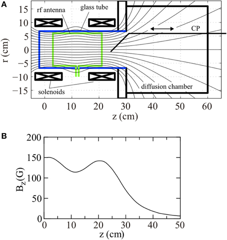
Figure 1. (A) Schematic of the “Chi Kung” expanding magnetic field plasma experiment showing main components (CP is the rf compensated Langmuir Probe) and (B) Bz component of magnetic field along the main axis.
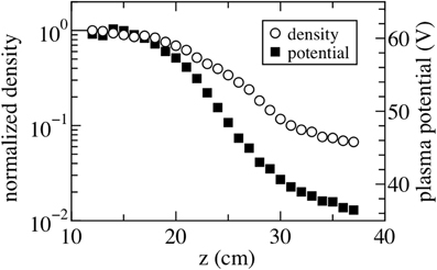
Figure 2. Normalized density (open circles) and potential (filled squares) along the main axis.
This situation has been investigated by Kaganovich et al. [9] where they showed that for an Electron Cyclotron Resonance plasma in a mirror for similar pressures as the present experiment, the trapped electrons will, to zeroth order, remain isotropic since they will eventually suffer random scattering collisions with neutrals before escaping to the walls. Extending this reasoning to the electrons trapped by the electric field in the expanding plasma it can be assumed that the electrostatically trapped electrons will also be isotropic. This is important for the experimental measurements using a Langmuir probe since the probe exposed area will collect electrons from all directions resulting in an eepf averaged over all pitch angles. For an isotropic eepf thus the Langmuir probe will yield correct eepf.
Experimental Setup
Experiments are performed in the “Chi-Kung” helicon reactor shown in Figure 1 and previously described in great detail elsewhere [4, 5, 8]. A 13.7 cm inner diameter and 31 cm long Pyrex glass tube (source tube) is contiguously connected to a 32 cm diameter and 30 cm long aluminum grounded diffusion chamber which is evacuated by a turbomolecular/rotary pumping system to a base pressure of ~10−6 Torr. Argon gas is introduced from a sideport on the diffusion chamber and the chamber pressure is maintained at 0.3 mTorr, measured by a baratron gage connected to another sideport. Two solenoids situated around the source tube are supplied with 6 A current; the calculated magnetic field strength on axis is plotted in Figure 1B. The field has a weak mirror configuration with maxima of ~140 Gauss at z ~ 3 and 20 cm, gradually decreasing to ~15 G at z = 40 cm. A double-saddle rf antenna surrounds the source tube shown in Figure 1A and is powered from a 13.56 MHz rf generator via an impedance matching circuit. Both the forward and reflected rf powers are monitored by directional couplers and the forward power is chosen as 250 W for these experiments so that the plasma is maintained in the “high density” mode. The matching circuit is tuned so as to minimize the reflected rf power (typically less than a few Watts). Under similar conditions, previous experiments have shown a plasma density of 3 × 1010 cm−3 in the source tube and the presence of a potential drop near the source exit [4].
Measurement of the eepfs are performed using an axially movable rf-compensated Langmuir probe (CP) inserted via a vacuum port on the downstream end vacuum flange [5]. The eepf can be obtained from the second derivative of the current-voltage (Ip/Vbias) characteristics of the Langmuir probe using the well-known Druyvesteyn method implemented here by an analog differentiation technique. The “as measured” axial eepfs are shown on Figure 3A: the local plasma potential Vp is given by the zero-crossing point of the second derivative and the energy of the electrons is given by εe = −Vbias + Vp where Vbias is the voltage applied to the Langmuir probe. The eepfs on Figure 3A are plotted by keeping the same X label range of Vbias = 0–60 V to show that Vp at z = 19 cm is 58 V decreasing to Vp = 32 V at z = 37 cm (see also Figure 2).
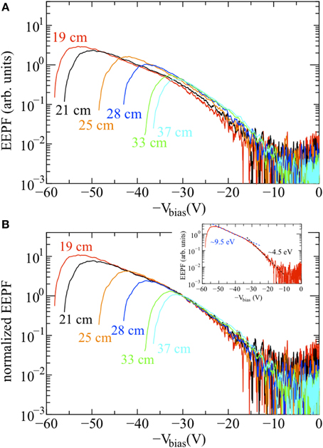
Figure 3. (A) As measured EEPFs and (B) EEPFs normalized at Vbias = 30 V for increasing axial positions (from z = 19–37 cm); the inset on (B) is the EEPF measured at z = 19 cm showing the two Maxwellian fits (dotted lines) for the trapped (9.5 eV) and escaping (4.5 eV) electrons; the break energy is defined as the intersection between the two fits.
Once the eepf gp(εe) is measured, the plasma density can be calculated as
The very low energy part (typically less than 0.5Te) of the eepf is often distorted by the surface condition of the probe and imperfect compensation of the rf oscillation. This can be exacerbated by a poor choice of probe impedance which has been discussed at length by Godyak and Piejak [3]. Fortunately, this is not particularly important for the present discussion which is mainly focusing on the energetic part of the eepf above εe = −Vbias + Vp ~ 10 eV. The eepfs presented here have been taken over about two orders of magnitude of plasma density and although the plasma impedance changes considerably, the curves appear well-behaved for energies above 4 eV, i.e., 1/2 of the Te ~ 9 eV obtained from the slope of the eepf below the break energy (at Vbias ~ 30 Volts which separates the low energy electrons with a Te ~ 9 eV and the high energy electrons with a Te ~ 4.5 eV).
The rightmost azimuthal band of the antenna is situated close to the maximum of the magnetic field at z ~ 20 cm (Figure 1) so upstream of this position it would be expected that electrons would be affected by a mirror type configuration while downstream the dynamics would be dominated by the expanding plasma. Another experimental constraint is non-uniformity of the magnetic field: as can be seen from Figure 1, the first magnetic field line that can enter the chamber without touching the exit of the source passes through a radius of 4 cm at the magnetic field maximum, about 3 cm from the source tube wall. This is also the skin depth for the measured average plasma density so for radii greater than ~4 cm the electron temperature would increase toward the radial wall whereas for smaller radii there would be a diffusive equilibrium dominated by the collisional behavior of the trapped electrons. The results of Takahashi et al. appear to confirm this [8].
Results and Discussion
In Figure 3A the eepfs, as-measured by the Langmuir probe for z = 19–37 cm, are presented. Referring to Figure 1B this is where the magnetic field decreases smoothly. The general similarity of form between the curves in Figure 3A can be seen but the amplitudes do not match very well, especially for the larger axial distances. The effect of forcing the curves to be equal to unity at a −Vbias of −30 Volts is shown in Figure 3B and is visually stunning; all the eepfs can be seen to lie on the same universal curve. There is some divergence for the high energy electrons (|Vbias| < 20 V) where the density is down by a factor of 1000 and the experimental error can be seen to be quite large. For the fitting, the variance was measured to be ±16% which is considered acceptable given the uncertainties involved with all Langmuir probe measurements. These results clearly show that as the plasma expands, the eepfs are only changed by the amplitude factor exp(e(Vp-Vp,max)/(kTe)).
The axial plasma density measured by the Langmuir probe and integrating the eepf was adjusted by the same fitting factor as that used to produce Figure 3B and along with the plasma potential Vp obtained from the zero crossing of the eepfs are plotted in Figure 4. In order to have some confidence in the axial measurement of the electron temperature, given that the Langmuir probe measures electrons with all pitch angles as discussed above, the Boltzmann equation was used to determine the electron temperature along the axis using:
where Vp is the plasma potential relative to ground, Vp, 19 the plasma potential at an axial distance of 19 cm.
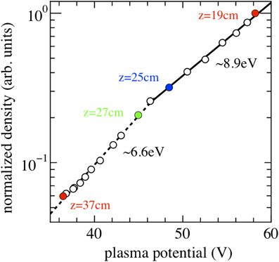
Figure 4. “Boltzmann” plot of normalized density vs. plasma potential showing trapped electrons (z = 19–25 cm, solid line) with a temperature of 8.9 eV and free electrons (z = 25–37 cm, dotted line) with a temperature of 6.6 eV.
In Figure 4 the logarithm of the plasma density (in arbitrary units) is plotted as a function of the plasma potential Vp for z = 19–37 cm. Fitted to these points are two straight lines which can be considered to represent electron temperatures. The slope of the high density line is about 8.9 eV and the lower density 6.6 eV, the two appearing to join at an axial distance between 25 and 27 cm. As mentioned in previous work [4, 8], the higher temperature electrons are those trapped in the source region by the electrostatic potential generated by the electron pressure of the gradient in plasma density along the axis. The cooler electrons are those that are free and can surmount the potential barrier and travel to the far end of the diffusion chamber. The upstream electron temperature agrees well with that deduced from the slope of the eepfs; the downstream is somewhat higher than that of the eepfs. A possible explanation could be related to downstream ionization which would increase the downstream density somewhat leading to the apparently higher temperature shown in Figure 4.
A very interesting theoretical investigation of the behavior of electrons in a magnetic nozzle has been carried out by Arefiev and Breizman [10, 11] where they find that the total energy of the “coupled electrons” is conserved, i.e., those that are reflected by the electric potential in the expanding plasma (our trapped electrons) in the nozzle back into the plasma source. They discuss the second group of electrons that escape over the potential barrier but encounter a rarefaction wave far downstream of the source. These they call uncoupled electrons and they appear similar to the electrons that we call free, since in the present experiment these electrons encounter the downstream plasma and the boundary sheath, some being reflected there and the more energetic ones escaping to the right hand boundary of the vacuum vessel. Our results appear to validate the theory of Arefiev and Breizman surprising well, given the shortcomings of the experiment and the difficulties in measurement described above. We now have experiments underway that will go some way in ameliorating this situation: the plasma will be expanding into a volume of some cubic meters and the boundary wall will be about 4 m distant. The pumping rate in the new experiment will be about 200 times greater allowing a much closer comparison with the theory.
Conclusion
The primary aim of this work was to show that for conditions where a magnetized plasma is in free expansion, i.e., the mean free path for electron neutral collisions is greater than the scale length of the plasma system, the eepf can be described by non-local parameters [12–14]. A rf compensated Langmuir probe was used to measure the eepfs which were then normalized by a small factor so that they coincided at one bias voltage (−30 V). The electron densities obtained from the integral of the normalized eepfs were plotted against the plasma potential obtained from the zero crossing of the eepfs and the electron temperatures thus obtained agreed well with the slopes of the eepfs.
The self consistency of the measurements suggest that the trapped electrons are indeed isotropic and the Langmuir probe is producing reliable measurements.
Conflict of Interest Statement
The Review Editor J. P. Sheehan declares that, despite having collaborated with author Igor Kaganovich in the past 2 years, the review process was handled objectively. The authors declare that the research was conducted in the absence of any commercial or financial relationships that could be construed as a potential conflict of interest.
Acknowledgment
Part of this research was funded by the Australian Research Council (Discovery Projects DP1096653 and DP140100571), and the Grant-in-Aid for scientific Research (B25287150) from the JSPS and by US. Deparment of Energy.
References
1. Tsendin LD. Electron kinetics in glows—from Langmuir to the present. Plasma Sources Sci Technol. (2009) 18:014020. doi: 10.1088/0963-0252/18/1/014020
2. Kortshagen U, Tsendin LD. Fast twodimensional selfconsistent kinetic modeling of lowpressure inductively coupled RF discharges. Appl Phys Lett. (1994) 65:1355–7. doi: 10.1063/1.112050
PubMed Abstract | Full Text | CrossRef Full Text | Google Scholar
3. Godyak VA, Piejak RB. Paradoxical spatial distribution of the electron temperature in a low pressure rf discharge. Appl Phys Lett. (1993) 63:3137–9. doi: 10.1063/1.110227
4. Charles C, Boswell RW. Current-free double-layer formation in a high-density helicon discharge. Appl Phys Lett. (2003) 82:1356–8. doi: 10.1063/1.1557319
5. Takahashi K, Charles C, Boswell RW, Kaneko T, Hatakeyama R. Measurement of the energy distribution of trapped and free electrons in a current-free double layer. Phys Plasmas (2007) 14:114503. doi: 10.1063/1.2803763
6. Meige A, Boswell RW, Charles C, Turner MM. One-dimensional particle-in-cell simulation of a current-free double layer in an expanding plasma. Phys Plasmas (2005) 12:052317. doi: 10.1063/1.1897390
7. Baalrud S, Lafleur T, Boswell RW, Charles C. Particle-in-cell simulations of a current-free double layer. Phys Plasmas (2011) 18:063502. doi: 10.1063/1.3594565
8. Takahashi K, Charles C, Boswell RW, Hatakeyama R. Radial characterization of the electron energy distribution in a helicon source terminated by a double layer. Phys Plasmas (2008) 15:074505. doi: 10.1063/1.2959137
9. Kaganovich I, Misina M, Berezhnoi SV, Gijbels R. Electron Boltzmann kinetic equation averaged over fast electron bouncing and pitch-angle scattering for fast modeling of electron cyclotron resonance discharge. Phys Rev E Stat Phys Plasmas Fluids Relat Interdiscip Topics (2000) 61:1875–89. doi: 10.1103/PhysRevE.61.1875
PubMed Abstract | Full Text | CrossRef Full Text | Google Scholar
10. Arefiev AV, Breizman BN. Ambipolar acceleration of ions in a magnetic nozzle. Phys Plasmas (2008) 15:042109. doi: 10.1063/1.2907786
11. Arefiev AV, Breizman BN. Collisionless plasma expansion into vacuum: two new twists on an old problem. Phys Plasmas (2009) 16:055707. doi: 10.1063/1.311862
12. Kolobov VI. Advances in electron kinetics and theory of gas discharges. Phys. Plasmas (2013) 20:101610. doi: 10.1063/1.4823472
13. Godyak VA. Electron energy distribution function control in gas discharge plasmas. Phys. Plasmas. (2013) 20:101611. doi: 10.1063/1.4823075
PubMed Abstract | Full Text | CrossRef Full Text | Google Scholar
Keywords: low-temperature plasmas, plasma expansion, electron energy probability function, non-local effect
Citation: Boswell RW, Takahashi K, Charles C and Kaganovich ID (2015) Non-local electron energy probability function in a plasma expanding along a magnetic nozzle. Front. Phys. 3:14. doi: 10.3389/fphy.2015.00014
Received: 29 September 2014; Accepted: 06 December 2014;
Published online: 09 March 2015.
Edited by:
Earl E. Scime, West Virginia University, USAReviewed by:
J. P. Sheehan, University of Michigan, USAEarl E. Scime, West Virginia University, USA
M. Umair Siddiqui, West Virginia University, USA
Copyright © 2015 Boswell, Takahashi, Charles and Kaganovich. This is an open-access article distributed under the terms of the Creative Commons Attribution License (CC BY). The use, distribution or reproduction in other forums is permitted, provided the original author(s) or licensor are credited and that the original publication in this journal is cited, in accordance with accepted academic practice. No use, distribution or reproduction is permitted which does not comply with these terms.
*Correspondence: Rod W. Boswell, Space Plasma, Power and Propulsion Laboratory, Research School of Physics and Engineering, The Australian National University, Bldg., 60, Mills Road, ACT 2601 Canberra, ACT, Australia e-mail: rod.boswell@anu.edu.au