Semi-analytical model for hollow-core anti-resonant fibers
 Wei Ding
 Yingying Wang
- 1Laboratory of Optical Physics, Institute of Physics, Chinese Academy of Sciences, Beijing, China
- 2Institute of Laser Engineering, Beijing University of Technology, Beijing, China
We detailedly describe a recently-developed semi-analytical method to quantitatively calculate light transmission properties of hollow-core anti-resonant fibers (HC-ARFs). Formation of equiphase interface at fiber's outermost boundary and outward light emission ruled by Helmholtz equation in fiber's transverse plane constitute the basis of this method. Our semi-analytical calculation results agree well with those of precise simulations and clarify the light leakage dependences on azimuthal angle, geometrical shape and polarization. Using this method, we show investigations on HC-ARFs having various core shapes (e.g., polygon, hypocycloid) with single- and multi-layered core-surrounds. The polarization properties of ARFs are also studied. Our semi-analytical method provides clear physical insights into the light guidance in ARF and can play as a fast and useful design aid for better ARFs.
Introduction
Hollow-core optical fibers can be used as hosts for light [1], matter [2], and their interactions [3, 4]. In a piece of hollow-core fiber (HCF), the large overlap of laser light and studied matter leads to significant advantages in applications known as lab-on-a-fiber. Such applications require a fiber with merits of broadband light confinement, low transmission attenuation, high damage threshold, and effective modal control. The first requirement enables light-matter interactions to occur at different spectral lines, the second one guarantees the efficiency of such interactions, the third one allows high power laser getting access to the fiber, and the fourth one allows atoms or molecules to act with controlled light modes. All these requirements help to duplicate an environment similar to or even better than optical bench inside a HCF.
Aiming at these attractive applications, several methods of guiding light in HCF have been explored. By opening an out-of-plane photonic bandgap (PBG) below the air-line, all the outwardly-propagating passageways are blocked in the periodical cladding region, which enables light confinement in the air core defect. This mechanism has been explicitly demonstrated in the density of optical states (DOS) plot [5, 6]. The PBG-induced light confinement becomes stronger as the number of cladding layer increases and thus, in principle, the confinement loss of hollow-core photonic bandgap fiber (HC-PBGF) can reach ultimate low value until the surface scattering loss dominates [7]. To our understanding, this unambiguous and quantitative interpretation on the guidance mechanism results in the fast development of HC-PBGF in the first decade of Twenty First century. The optical attenuation has reached a record of 1.2 dB/km [7]; entire fabrication procedure of a HC-PBGF can be completed within 1 day; the anti-crossing between the core mode and the surface mode has been clearly identified [8, 9] and can be deliberately engineered for specific purposes, e.g., polarization maintaining in HC-PBGF [10, 11]. However, the intrinsic ~70 Thz transmission bandwidth originating from the PBG guidance mechanism and the low damage threshold caused by large spatial overlap of the core mode with the glass cladding [7, 12] limit the lab-on-a-fiber applications in this kind of HCFs.
Another way to guide light in HCF is to utilize the anti-resonant reflecting effect of the glass wall [13]. Actually, the hollow-core anti-resonant fiber (HC-ARF) and its leaky core mode have been investigated for decades [14–16]. However, only in recent years, the introduction of hypocycloid [17] or negative curvature [18] core-surround structures revived the development of HC-ARF since it enables coexistence of broadband light confinement (200–800 THz) and low transmission attenuation (20–100 dB/km depending on the wavelength) [19, 20]. Furthermore, the spatial overlap of the core mode with the glass material is universally one order of magnitude smaller in HC-ARF than in HC-PBGF [21]. Having fulfilled the first three requirements proposed above [22], HC-ARF looks very promising for the lab-on-a-fiber applications. Meanwhile, unlike HC-PBGF, which has a typical honeycomb cladding structure [23], the HC-ARF catalog contains a great number of structure selections including Kagome lattice [17], square lattice [24], multi-fold circular arrangement of capillary tubes [18], nested capillary tubes [25, 26], etc… With continuous appearance of new ARF structures, more and more researchers realize that the degree of freedom of the cladding arrangement possesses great engineering potentials for attractive fiber properties, while, the basic anti-resonant reflecting optical waveguide (ARROW) principle [13] only cares about individual cladding elements and ignores their arrangement.
To better understand HC-ARF, many theoretical efforts have been implemented, such as low DOS interpretation [27], inhibited coupling between the core mode and the circulating resonances along the glass web [28], radial light confinement by concentric glass rings [29], and overall spatial overlap between the core mode and the glass [30]. However, only qualitative conclusions can be drawn from these models. Lack of an analytical or semi-analytical but quantitative model for HC-ARF has resulted in severe reliance on simulation and empirical guess in searching better-performance fiber. Therefore, a method, which can explicitly calculate the influences of different geometries on the properties of HC-ARFs and can act as a design aid in the context of comparative study, is highly demanded.
In this paper, we give a detailed description of our recently-developed semi-analytical method [31]. Its capability of quantitatively calculating light transmission properties of HC-ARFs is manifested in the search of better-performance ARF. Being aware that the discrete translational symmetry of the periodic cladding structures cannot be utilized here as in HC-PBGF, we abandon the conventional method of calculating DOS. We start from the simplest cladding structure, i.e., the single-wall ARF, and focus on the light leakage process in fiber's transverse plane. Formation of equiphase interface at fiber's outermost boundary and outward light emission in fiber's environment area ruled by a Helmholtz equation constitute the basis of our method. Many mathematical approximations are adopted to estimate the quantities needed in our calculations. Utilizing this mothod, we calculate the HC-ARFs having various shapes of single- and multi-layered core-surrounds. Good agreements are obtained between our model and numerical simulation. Our model is also used to calculate the hypocycloid-shape ARF and the polarization properties. As mentioned above, the hypocycloid-shape ARF has excellent properties of low attenuation and the polarization control in ARF, which is part of the modal control, is an important requirement for lab-on-a-fiber applications. For all these aspects, i.e., the geometry tunability (including hypocycloidal ARF shape), the layered core-surround structure, and the polarization properties, our semi-analytical model provides clear physical insights and could play as a fast and useful design aid.
This paper is organized as follows. In Section Leaky Mode in M-type Slab Waveguide, the leaky mode of a one-dimensional (1D) slab waveguide is solved. The relationship between the attenuation coefficient and the field amplitude at the outermost boundary is derived. In Section Geometry Transformation from Fiber to Slab, the mathematical problem of the 2D ARF is simplified to a 1D problem by using a hypothetical geometry transformation and many approximate relationships. The quantitative calculation capability of our model is demonstrated in varieties of single-wall ARFs. In Section Geometry Dependence of ARF Attenuation, our model is used to study the geometry tunability of the transmission properties in single-wall ARFs, including polygon and hypocycloid-shape ARFs. The multi-layered core-surrounds and the polarization properties of ARFs are investigated in Sections Multi-Layered Core-Surround and Polarization Properties of ARF respectively. The last section summarizes the fundamental principles and future developments of our model.
Leaky Mode in M-Type Slab Waveguide
To begin with, we consider the leaky mode in a 1D waveguide [14]. The core (with the thickness of 2r') and the environment of this slab waveguide are filled with air (n1 = 1), while the cladding consists of one layer of glass with the refractive index n2 = 1.45 and the thickness t = 0.67 μm (Figure 1A). The electric field distributions of the fundamental core mode, whose field profile is peaked at the central axis, can be written as,
where z (x) represents the direction along (transverse to) the propagation, the s and p polarizations are denoted in Figure 1A. The propagation constant β is equal to k0Re(neff) with k0 the propagation constant in vacuum and neff the effective modal index. The transverse wave-vector kxj is defined as . The field amplitudes, A's, the phases, φ's, and the complex effective index, neff, can be derived from boundary continuity conditions by using a simple root-finding algorithm [32].
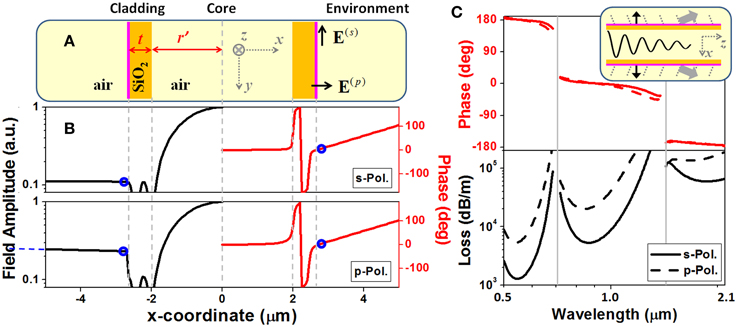
Figure 1. (A) Schematic of an M-type slab waveguide. (B) Distributions of the amplitudes (logarithmic scale) and the phases of the major electric field components in the s and p polarizations (Ey and Ex, respectively). r' = 2 μm, t = 0.67 μm, n2 = 1.45, and λ0 = 0.938 μm. (C) Phase of electric field at the outermost boundary (the pink lines in the insert) and attenuation of the fundamental core mode as a function of the wavelength. The gray lines in (C) stand for the resonant wavelengths.
With respect to the leaky mode characteristics, Equation (1) shows that the field in the environment only possesses the outward-propagating wave, whereas the fields in the core and in the cladding form standing waves. Moreover, the transverse wave-vector, kx1, has a positive imaginary part, leading to an exponential growth of field amplitude as x → ±∞ [14]. Strictly speaking, for a waveguide made from lossless dielectric, a finite number of guided modes and a continuum of radiation modes constitute the complete set of orthogonal basis. Leaky modes, which are mathematical solutions under the assumption that no inward-propagating wave exists in the outermost layer, are not members of this orthogonal basis. However, detailed analyses have verified equivalence between this mathematical simplification and realistic physical process of energy diffusion in a radiation mode continuum [14]. Figure 1B plots the amplitudes and the phases of the leaky modes of an M-type slab waveguide. The field amplitude in the environment grows exponentially as indicated by the blue dashed line. The attenuation coefficient of the leaky mode can be derived from, .
Field distribution of leaky mode can also be understood in the context of energy conservation [14]. The energy decrease in the longitudinal direction, owing to attenuation, should be equal to the energy leakage in the transverse directions. As illustrated in the insert of Figure 1C, many outward-inclined plane waves propagate in the environment region of the waveguide, and their oblique angles can be estimated from longitudinal phase-matching conditions. Actually, from Equation (1), we can derive an approximate relationship between the complex effective index and the field amplitude at the outermost boundary of the slab waveguide,
Here, only the transverse field components, i.e., the major field components, are employed, E(x+) is defined as △x→0+ E(x + △x), and the fundamental core mode requires Re(kx1)≈ π/2r′. To check the accuracy of Equation (2), we read out the field amplitudes at the outermost boundary from Figure 1B (marked by the blue circles), estimate , and deduce the imaginary parts of the effective indices for the s and p polarizations to be 1.08 × 10⁻⁴ and 4.77 × 10⁻⁴, respectively. These two numbers match well with the precisely calculated results based on standard root-finding algorithm [Im (neff) = 1.08× 10⁻⁴ and 4.73 × 10⁻⁴, respectively]. Moreover, Equation (2) hints that the complex effective index of the leaky mode can help us to estimate electric field amplitude at the outermost boundary in the circumstance of slab waveguide. Equation (2) bypasses the profile of the field distribution and straightly relates the field amplitude at one specific position with the effective modal index.
Figure 1B also plots the phase profile of the leaky modes. Reading out the phase values at the outermost boundary (marked by the blue circles), Figure 1C plots their variations with the wavelength. Surprisingly, these phases seem to be locked to some certain numbers determined by the anti-resonant order of the transmission band. Indeed, this phase-locking effect is irrelevant to the polarization and the geometrical dimension, and can be derived from the continuity conditions of the tangential field components at the outermost boundary under the condition of |kx2| ≫ |kx1|.
Figure 1C also plots the attenuation spectra. Apart from a set of identical resonant wavelengths λ0 ~ 0.7 and 1.4 μm, which are approximately determined by the ARROW formula of with m being an integral [13], different polarizations exhibit different attenuations. Inside every transmission band, the p polarization shows much worse light confinement than the s polarization, implying that, in the case of a hybrid polarization, the p-polarization component perhaps plays the primary role in light leakage.
Altogether, in 1D, the leaky mode of a hollow-core waveguide can be easily solved. All the information about the electric field, i.e., amplitude, phase, and polarization, at the outermost boundary can be approximately derived from either the complex effective index (Equation 2) or some basic properties, like the phase-locking effect exhibited in Figure 1C. To solve the effective index of the leaky mode, we need to use numerical approach, but only to the extent of finding roots of a differential equation with one variable.
Geometry Transformation from Fiber to Slab
Transverse cross section of generic HC-ARF is a 2D geometry. Increase of dimensionality causes decrease of geometrical symmetry, making analytical modeling more difficult. In order to simplify this problem, a proper geometry transformation from fiber to slab waveguide may be helpful. We start this attempt in the most symmetric 2D structure, i.e., single-wall circular ring fiber.
Figure 2A depicts a circular ring ARF with the inner radius r = a and the glass thickness t. We argue that the radial light leakage at one azimuthal angle ϕ (defined by the green arrow) is equivalent to that in a slab waveguide having the inner radius r′ and the same glass thickness t. Since the transverse light confinement is now relaxed from 2D (the x-y plane) to 1D (the x direction), we hypothesize . Meanwhile, the corresponding segment of the fiber needs to be rotated till it is parallel with the y axis. The electric field vector of the fiber mode also needs to be rotated by the same degree. After the geometry transformation, the electric field amplitude at the outermost boundary of the fiber can be approximately obtained from the complex effective indices neff(s,p)(ϕ) of the leaky modes in the corresponding slab waveguide,
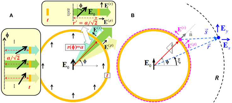
Figure 2. (A) Geometry transformation from a circular ring ARF to a series of slab waveguides. r and r' represent the inner radii's of the fiber and the slab respectively. (B) Evaluating and integrating the outward-propagating electromagnetic waves in the transverse plane by using Green's theorem.
Here, the superscripts represent the s and p polarizations. Equation (3) is the same as Equation (2) except the empirical adjustment from r′ to a/2. Meantime, the proportions of the s and p polarization components in each angular segment (cos2ϕ and sin2ϕ, respectively) can be directly obtained from the geometry transformation (Figure 2A). The phases of the electric fields at the outermost boundary are set to be a fixed number like what does in the slab waveguide.
Now, the overall modal index of the fiber, which is composed of different angular segments, is approximately calculated by arithmetically averaging the real parts of the effective indices of the leaky modes in all the generated slab waveguides over both polarizations,
This overall modal index leads to an estimate of the transverse k-vector, . The electric field in the environment of the fiber should obey a 2D scale Helmholtz equation in the x-y plane defined as ∇T2Ex,y(x,y) + kT2Ex, y(x, y) = 0. Note that both the x and y electric field components are the scale solutions of this Helmholtz equation. The transverse-wave nature of a propagating electromagnetic wave is maintained in three dimensions. However, in the case of glancing incidence, the transverse k-vector and the transverse electric field vector can be in the same direction. Now, we introduce a 2D Green's function, , which satisfies ∇T2G + kT2G = δ(r − r′) with δ(·) being the Dirac delta function. Here, the Hankel function of the first kind of order zero, H(1)0(kTs), has the asymptotic formula of as s goes to infinity. Utilizing Green's theorem, the electric field components in the environment area of the fiber can be expressed as an integral [33],
Here, the outermost boundary of the fiber forms a closed integral path, whose normal direction is defined by n. All the symbols used here are denoted in Figure 2B.
If we assume fiber's outermost boundary forms an equiphase interface for both s and p polarizations, this boundary also constitutes an equiphase interface for the x/y-components of the electric field, the normal derivatives of Ex,y can be approximated to be . Using the asymptotic expression of the Hankel function, as s goes to infinity. Substituting all these formulae into Equation (5) yields the electric field in the far-field region,
where is the Kirchhoff's inclination factor in the Huygens-Fresnel principle, and Ex,y at fiber's outermost boundary can be simply derived from the s/p-components,
Based on Equation (6), we further integrate all the outward-propagating energy flows in the transverse plane, which should be equal to the energy attenuation in the longitudinal direction.
Here, Δz is the differential distance in the propagation direction, the radiation angle in the transverse plane is represented by ξ, the integration is implemented in the far-field region (s → +∞), and the field distribution inside fiber's core is approximated to be a Gaussian function of |E(x, y)| = |E0| · exp(−r2/2A2) with .
Finally, the fundamental core mode requirement of kT · a ≈ π/2 and the Equation (3) yield,
It is noteworthy, in deriving Equation (9), we use many approximate relationships. The purpose is to simplify mathematical treatments and to highlight physics underneath the light leakage process. Detailed derivation can be found in our recent paper [31]. Below, this approximate method will be compared with precise calculation and simulation in several ARF structures.
The first example is the single-wall circular ring fiber, which can be precisely calculated by using transfer matrix technique and Bessel functions in cylindrical coordinates [34]. For the leaky core mode, the environment of the fiber only contains outward-propagating Hankel functions. Figure 3 shows the modeled and the precisely calculated propagation constants and attenuations for three fiber core sizes. A good agreement between two calculations is found in a broad wavelength range and implies that our semi-analytic method grasps the physical essence and may be useful in treating more complicated ARF structures.
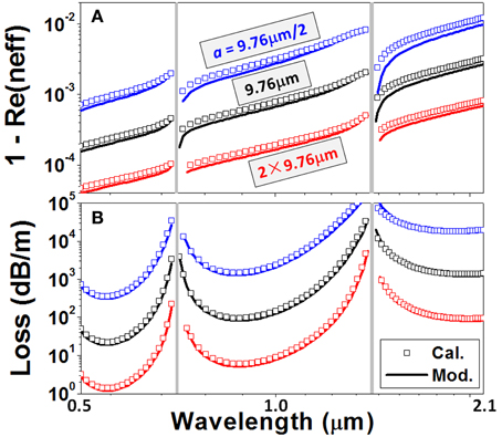
Figure 3. (A) Propagation constants (the real parts of the effective indices) and (B) attenuations of three circular ring ARFs as a function of the wavelength. The precisely calculated results (the hollow squares) are from a transfer matrix approach [34], and the modeled results (the solid lines) are from Equation (9). t = 0.67 μm.
The fact that our semi-analytical method can deal with more complicated structures promptly is demonstrated in the second example. In Figure 4A, a single-wall square ARF having 4 rounded corners is calculated by both the numerical simulation and semi-analytical modeling. Note that the latter is much faster than the former. For the numerical simulation, a full-vector finite-element method (FEM) solver (Comsol Multiphysics) and a proper mesh size and perfectly matched layer (PML) configuration [35] guarantee a less than 0.5% uncertainty. The rounded corners ensure the smoothness of the simulated spectra, because any knot structure on glass web, like corner apex or touching point, will deteriorate the transmission property [36]. On the other hand, in semi-analytical modeling, the fiber-to-slab geometry transformation is used and decreases the complexity of treatment by converting the mathematical problem from 2D to 1D (Figure 4A). Taking into account the varied inner radius with the azimuthal angle, r(ϕ), Equation (3) needs to be multiplied by an additional factor , and the differential length along the outermost boundary needs to be modified to dL = dl′ = dl/sin(θ − ϕ). All these symbols have been defined in Figure 4A. Figure 4B shows that our semi-analytical modeling agrees well with the numerical simulation in a broad wavelength range.
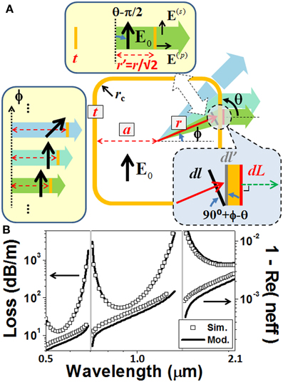
Figure 4. (A) Geometry transformation from a square ARF to a series of slab waveguides. (B) Semi-analytically modeled (the solid lines) and numerically simulated (the hollow squares) attenuations and propagation constants of the fundamental core mode as a function of the wavelength (logarithmic scale). a = 9.76 μm, t = 0.67 μm, and rc = 2.5 μm.
Our next example is a single-wall triangle ARF. In this structure (Figure 5A), we examine the distribution of the electric field amplitude and the phase at the outermost boundary (0.5 μm offset outwards). At the anti-resonant wavelength of 910 nm, Figure 5B compares the results of our semi-analytical model and numerical simulation. Two orthogonal polarizations are considered, and only the major electric field components are plotted. In Figure 5C, the intensities of the major electric field components are also plotted at a far-distance circle R. Both semi-analytical modeling and numerical simulation are employed, and Fraunhofer far-field criterion (R = 90 μm ≈ 2D2/λT [37], where D is the largest transverse dimension and λT is equal to with neff the effective index) is used to guarantee the validity of our model (i.e., the far-field requirement of Equation 6). Note that, in calculating Figure 5C, our semi-analytical model uses the accurate neff obtained from the simulation (rather than the estimated one from Equation 4). Other parameters in Equation (6) are obtained from our approximate approach.
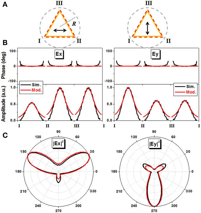
Figure 5. (A) Schematics of a single-wall triangle ARF and two orthogonal polarizations. (B) Semi-analytically modeled (the red lines) and numerically simulated (the black lines) electric field amplitudes and phases at the outermost boundary (0.5 μm offset outwards). (C) Modeled (the red lines) and simulated (the black lines) electric field intensities at a far-distance circle R. a = 9.76 μm, t = 0.67 μm, R = 90 μm, and λ0 = 0.91 μm.
It is seen that, with regard to both near field and far field, our semi-analytical model agrees well with the simulation. The azimuthal angle dependence of the light leakage is strongly influenced by the shape of the ARF. The phase-locking effect and the 2D Helmholtz equation play the primary roles in the light leakage process. In specific, the light radiations pointing at the corner apexes are suppressed, whereas those in the directions normal to the triangle sides are enhanced. Most energy is escaped from the sides nearly vertical to the polarization direction, where more p polarization components interact with the glass wall. With this understanding, in order to decrease attenuation, more light confinement structures should be deployed in these heavily leaking directions. With regard to the near field amplitude distributions, our modeling explicitly interprets the polarization dependence, like what exhibits in slab waveguide (Figure 1C), however, over-estimates the field amplitude around the corner apexes. This may be attributed to the fact that our model ignores the influences from adjacent angular segments.
Shortly speaking, in this section, we describe an approximate but semi-analytical model for solving the complex effective index of the leaky mode in a 2D single-wall ARF. Our method exhibits very good quantitative calculation characteristic, which may provide us a powerful tool to unveil the light confinement mechanism of ARF.
Geometry Dependence of ARF Attenuation
Transmission properties of ARF are very sensitive to its geometry. Indeed, recent intense study of this type of HCF should be partly attributed to the recognition that some geometries can effectively ameliorate transmission properties [17, 18]. To elucidate this geometry dependence, below, we will apply our semi-analytic method to more interesting single-wall ARF structures, i.e., regular polygon and hypocycloid shape. Numerical simulations will be accompanied with.
Figure 6 plots the attenuation spectra of several single-wall polygon ARFs. Square, hexagon, octagon, dodecagon, and circle stand for the typical core shapes that have been realized at present [17, 24, 28]. For all these fibers, the inscribed radius is fixed to be a = 9.67 μm. From Figure 6, it is seen that, apart from some spiky features, our semi-analytical model agrees well with the simulation, especially with regard to the variation tendency of different fiber shapes. As the number of the polygon edges increases, the ARF shape becomes more and more alike a circle and the light confinement becomes worse and worse. From the viewpoint of equiphase interface, a convex outer-most boundary is inclined to leak more light into the environment.
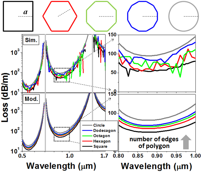
Figure 6. Simulated and modeled attenuations of single-wall square (black), hexagon (red), octagon (green), dodecagon (blue), and circular (gray) fiber. a = 9.76 μm, t = 0.67 μm.
We therefore study a concave ARF shape, i.e., the hypocycloid shape [17]. In Figure 7A, our semi-analytical model and numerical simulation both give evidences that a hypocycloid-shape square ARF has better light confinement than a square ARF if their inscribed radii's are the same. As discussed above, the phase-locking effect of fiber's outermost boundary should play some roles. Figures 7B,C plot the simulated phase distributions of these two fibers at the working wavelength of 0.91 μm. The phases at fiber's central axes (0, 0) are set to be zero, and the dark red lines in two plots represent the contours of 20°. It is clearly seen that the 20° equiphase interface of the square fiber has been converted to a circular one because of light diffraction. While the phase-locking effect causes the 20° equiphase interface of the hypocycloidal fiber to move toward the direction pointing at the corner (Note that the dashed dark red line in Figure 7C is a copy of the dark red line in Figure 7B). Additionally, the phase increase in the radial direction (Figures 7B,C) is a typical feature of leaky mode (see Figure 1B for the 1D slab case).
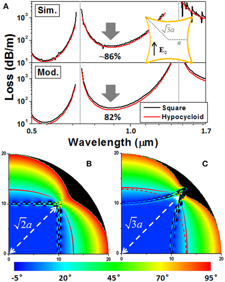
Figure 7. (A) Simulated and modeled attenuations of a single-wall square ARF (the black lines) and its hypocycloidal variant (the red lines). (B,C) Phase distributions of these two fibers. The phases at fiber's central axes (0, 0) are set to 0°, and the dark red lines represent the contours of 20°. The dashed dark red line in (C) is a copy of the dark red line in (B). a = 9.76 μm, t = 0.67 μm, and λ0 = 0.91 μm.
We notice that there exist fast phase oscillations along glass webs in Figures 7B,C. These represent some evanescent field components, which do not contribute to far-field light emissions. For an effective transverse wavelength of , these fast oscillatory field components cannot satisfy phase-matching condition with outward-propagating waves. A short offset in the outward direction, e.g., 0.5 μm, is sufficient to get rid of these oscillation components.
Multi-Layered Core-Surround
A realistic ARF possesses more complicated core-surround. Extending our semi-analytical model to multi-layered structures is therefore important. Here we consider an ARF having a high/low/high-index trilayer (H/L/H) outside its air core. For the structure shown in Figure 8A (also known as Bragg fiber [34]), our semi-analytical method regards the H/L/H trilayer as a whole core-surround. When implementing the fiber-to-slab geometry transformation, the core radius is converted to , while other geometrical parameters are preserved. The electric field distributions in the resulted slab waveguide can be written as [14, 16],
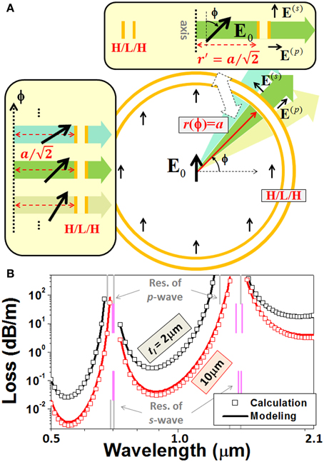
Figure 8. (A) Geometry transformations from a circular ARF having an H/L/H core-surround to a series of slab waveguides. The core-surround structures in the fiber and in the slab are identical. (B) Precisely calculated (the hollow squares) and semi-analytically modeled (the solid lines) attenuations of the fiber for the thickness of the low-index layer, tl, to be 2 μm or 10 μm. a = 15 μm, and th = 0.67 μm.
Here, th (tl) represents the thickness of the high (low) index layer, and the transverse wave-vectors are . Searching complex effective index and approximately estimating electric field amplitude at the outermost boundary can be done by using the standard eigenvalue-finding algorithm in this new slab structure [31, 32]. Section Leaky Mode in M-type Slab Waveguide has described this method.
For a circular ARF shown in Figures 8A,B compares our semi-analytically modeled results with the precisely calculated ones [34]. Very good agreement is obtained, albeit the thickness of the low-index layer varies largely. Figure 8B also shows the necessity of a more accurate prediction to the resonant wavelengths (marked by the vertical lines). The approximate formula of the resonant wavelength, , obviously cannot distinguish the discrepancy between tl = 2 μm and tl = 10 μm.
Complying with the ARROW picture, the whole H/L/H core-surround plays the role of a medium, which transfers light energy from inside to outside of the air core. We argue that this energy transfer effect is maximized when the field distribution inside the core-surround forms a standing wave with the antinodes appearing at both ends. Firstly, the field distributions inside the H/L/H trilayer should be written as,
where a H/L/H slab structure is considered, and the origin of the coordinate x' is defined at one end of this trilayer. Secondly, in order to determine the phases Φ1,2, the continuity conditions of the tangential field components and the antinode requirements of the standing wave at both ends are used,
and yield,
Finally, using the approximate relationship of and the definitions of kx1,2 (see the text below Equation 1), the new resonant wavelength formula can be expressed as,
This new formula has been used across this paper and exhibits good accuracy in determining the transmission bands. For a single-wall ARF (tl = 0, th2 = 0, th1 = t), the resonant wavelengths of the s and p polarizations are identical and converted to the expression in Ref. [15]. For H/L/H-layered ARF, different polarizations and parities give rise to four sets of resonant wavelengths as exhibited in Figure 8B.
Incorporating the H/L/H core-surround into the hypocycloid-shape ARF, we model and simulate the square ARF again (Figure 9B). The results in Figure 7A are re-plotted for comparison (Figure 9A). Many discrepancies in terms of shape and magnitude of the attenuation spectra emerge between the single-wall and multi-layered ARFs. Hypocycloidal core-surround seems helpful to lower attenuation. Our semi-analytical model correctly predicts the variation tendencies from the single-wall to the H/L/H-trilayer and from the square shape to the hypocycloid shape. It is noteworthy the H/L/H hypocycloid geometry is similar with a recently proposed nested ARF structure [25, 26] (see Figure 9C).
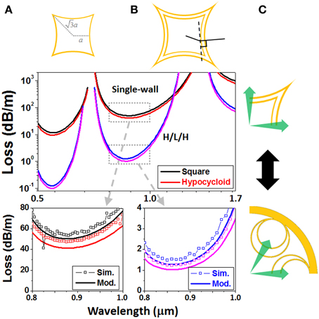
Figure 9. Semi-analytically modeled attenuations of (A) a single-wall square ARF (the black lines) against its hypocycloidal variant (the red lines) and (B) a H/L/H square fiber (the blue lines) against its hypocycloidal counterpart (the magenta lines). a = 9.76 μm, th = 0.67 μm, and tl = 1.5 μm. The agreement of modeling and simulation is manifested in the two zoom in plots. (C) Structural comparison between the ARF in (B) and the nested ARF in [25, 26].
Polarization Properties of ARF
Next, we discuss another important issue about ARF, i.e., the polarization properties. It is recently aware that polarization control in ARF is different from that in PBGF, where the anti-crossing between the core mode and the surface mode can be purposely utilized in a narrow wavelength range at the expense of fiber's transmission properties, e.g., attenuation and transmission bandwidth [11]. In ARF, the broadband transmission requirement restrains the utilization of the anti-crossing effect. Below, we present a study of the polarization properties of ARFs.
Two types of geometric asymmetries [38] are incorporated into an H/L/H-layered ARF. In Figure 10A, the air core radius (inner radius) is set to be r(ϕ) = a = 15 μm, the glass thicknesses vary from the vertical direction (tV = 0.67 μm) to the horizontal direction (tH = 0.6 μm), and ϕ stands for the azimuthal angle. On the other hand, in Figure 10B, an elliptical air core (aV = 15 μm, aH = 17 μm) is surrounded by a uniform H/L/H-trilayer. Figure 10 compares the modeled and simulated polarization properties, i.e., birefringence and polarization dependent loss (PDL). Both modeling and simulation reveal that different geometric asymmetries give rise to different polarization properties. Note that the formula of the resonant wavelengths (Equation 14) precisely determines the transmission bands. Varying glass thickness, t, results in remarkable shift of the resonant wavelengths, whereas varying air core radius, r, results in very few change of the resonant wavelengths.
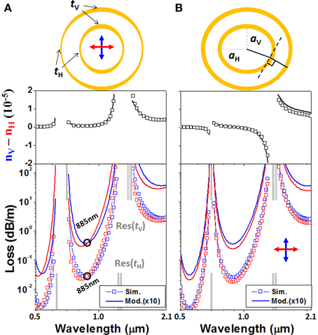
Figure 10. Modeled and simulated birefringence and PDL of ARFs having H/L/H core-surrounds. In (A), the glass thicknesses vary from 0.67 μm (in the vertical direction) to 0.6 μm (in the horizontal direction), whereas the inner radius (15 μm) and the outer radius (26.34 μm) keep unchanged. The modeled and simulated zero-PDL wavelengths both appear at 885 nm. In (B), an elliptical air core (15 μm × 17 μm) is surrounded by an H/L/H trilayer with th = 0.67 μm and tl = 10 μm. The black lines in schematic define the angular segment employed in the fiber-to-slab geometry transformation, i.e., the green arrow in Figure 8.
Replacing H/L/H-trilayer with twelve capillary tubes, we design two realistic ARFs (Figure 11). The similarity between Figures 10, 11 is manifest. Interestingly, in Figure 11, the numerical simulations also exhibit two kinds of polarization properties, just like what happens in Figure 10. Inside each transmission band, Figure 11A shows a larger propagation constant for the vertical polarization, whereas, only in the shorter wavelength half of the transmission band, the loss of the vertical polarization is higher than the horizontal polarization. On the other hand, in Figure 11B, the propagation constant of the vertical polarization is larger than the horizontal one in the shorter wavelength half of the transmission band, whereas the loss of the vertical polarization is always higher than the horizontal polarization. Additionally, the transmission bands in Figure 11A are narrower than those in Figure 11B because of the non-uniformity of glass thickness. In calculating these resonant wavelengths (the gray lines), we use Equation (14) and an equivalent H/L/H trilayer with the tl being either the inner diameter of the capillary or 2 μm (a typical chord length of the capillary).
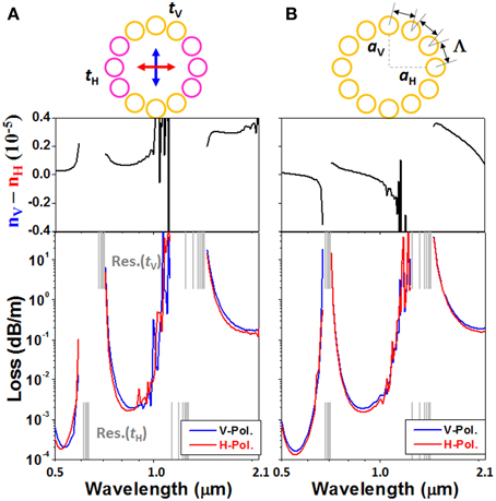
Figure 11. Simulated birefringence and PDL of ARFs composed of 12 capillary tubes. In (A), an air core with the radius of 15 μm is surrounded by two types of capillaries. The six yellow ones have an outer diameter of 10.2 μm and a glass thickness of 0.67 μm. The other six pink capillaries have the same outer diameter but a thinner glass thickness (0.6 μm). In (B), an elliptical air core (15 μm × 17 μm) is surrounded by identical capillaries (dout = 10.2 μm, t = 0.67 μm). All the capillaries are untouched with each other, and the distances between adjacent capillaries are the same. Note that the gray vertical lines obtained from Equation (14) define the transmission bands accurately.
Slightly modifying the geometries in Figure 11, we design another HC-ARF having a jacket tube and a more elliptical air core (Figure 12). Simulation reveals that most features about birefringence and PDL are retained. The attenuation of the vertical polarization is higher than that of the horizontal polarization by 2–3 times within a transmission band wider than 100 nm. In the same wavelength range, the sign of the birefringence keeps unchanged. The relatively lower birefringence comparing with a recently reported HC-PBGF (Δn ~ 2 × 10⁻⁴) [11] should be attributed to the fact that the transmission bands of our ARF stay far away from any mode anti-crossing. Larger birefringence in ARF may be possible, if mode anti-crossing is carefully introduced. However, the narrow bandwidth attribute of the anti-crossing effect perhaps deteriorate the property of broadband guidance of ARF.
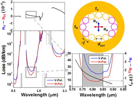
Figure 12. Simulated birefringence and PDL of a realistic HC-ARF. aV = 13 μm, aH = 19 μm, dout = 10.2 μm, tV = 0.67 μm (for the yellow capillaries), and tH = 0.6 μm (for the pink capillaries). All the center-to-center distances between adjacent capillaries are Λ = 10.96 μm > dout.
Discussions and Conclusions
In summary, a recently-developed approximate but semi-analytic method has exhibited quantitative calculation capability for a variety of HC-ARFs. Our calculation reproduces the attenuation and the polarization properties of ARF over broad wavelength range. Thanks to the following three newly-identified characteristics, our method points out some important effects occurring in the light leakage process of ARF, which provides deep physical insights and may play as an aid to both intuition and design.
• For single-wall or multi-layered ARFs, the phase of the electric field at the outermost boundary is determined by the order of the anti-resonant transmission band, irrespective of polarization, geometrical dimension and working wavelength. We tentatively introduce this attribute, derived in a slab waveguide, into 2D ARF structures. Fortunately, our conjecture is verified by the simulation results (Figure 5B) and leads to a very simple picture of equiphase interface. Using this a priori hypothesis, the evaluation of the complex electric field at fiber's outermost boundary is simplified to the estimation of its amplitude.
• The relationship between the longitudinal and the transverse k-vectors, k02neff2 + kT2 = k02n2, together with the leaky mode characteristics provide us additional means to deal with the light leakage problem. First, the real part of the longitudinal k-vector, k0Re(neff), stands for the propagation constant; and the real part of the transverse k-vector, Re(kT), defines a 2D Helmholtz wave equation in the cross section plane, ∇T2E + Re(kT)2E = 0. Second, the imaginary part of the longitudinal k-vector, k0Im(neff), is relevant to the attenuation, α, in the fiber waveguide and has relationship with the field amplitude at the outermost boundary in the slab waveguide. Third, once the electric fields at fiber's outermost boundary, rather than the entire field distribution in the whole cross section, is obtained, the light leakage energies in all the transverse directions can be integrated from Green's theorem. The shape of the fiber's outermost boundary influences the light leakage process via diffraction and will determine the overall attenuation.
• In order to simplify treatments, we proposed a fiber-to-slab geometry transformation, which converts the mathematical problem from 2D to 1D. By splitting fiber's cross section to different angular segments and converting them to a series of slab waveguides, the effective indices and the fields at slab's outermost boundary can be promptly and semi-analytically quantified. In this process, different polarization components should be separately dealt with. Additionally, based on the fundamental core mode property, the transverse field distribution inside fiber's air core is approximated to be a linearly polarized Gaussian beam. Every fiber's angular segment and the corresponding slab waveguide should contribute to the overall propagation constant and the light leakage equally.
However, we have to admit our model still contains some drawbacks. The first one is about the geometry transformation. As shown in Figure 4A, every fiber's angular segment is treated independently. The influences from adjacent segments are not taken into account, which may explain why the field amplitude in Figure 5B is over-estimated as the observation point approaches the corner apexes. The second drawback is that, at current stage, our model is only suitable for single- and multi-layered core-surrounds. Incorporating more complicated cladding structures into our model is demanded from the application viewpoint. We hope our current model can play as a platform for more powerful functionality in the future. The third drawback is that our method ignores the influences from corner apexes. Although the field amplitudes in these apexes are relatively weak according to simulation (Figure 5B), many spiky features in the attenuation spectra may be relevant to these components. The fourth problem of current model is the inaccuracy of the estimation to the overall propagation constant (Figures 3A, 4B). Altogether, if we can improve the evaluation accuracy of the electric field amplitude at the outermost boundary and the overall propagation constant, our model can be applied to more complicated and more realistic structures.
In principle, our method can be regarded as numerical, but only to the extent of root-finding of the differential equation with one variable. Utilizing a simple and clear picture of equiphase interface and outward light emission governed by a 2D Helmholtz wave equation, our model grasps the physical essences of the light leakage process in HC-ARF. Additionally, we simplify the mathematical treatments by having adopted many approximate relationships. Such a model has exhibited the capability of quantitatively calculating attenuation and polarization properties. More interesting applications are in prospect.
Conflict of Interest Statement
The authors declare that the research was conducted in the absence of any commercial or financial relationships that could be construed as a potential conflict of interest.
Acknowledgments
This work was supported by the National Natural Science Foundation of China (No. 61275044, 61377098, and 11204366), the Instrument Developing Project of the Chinese Academy of Sciences (No. YZ201346), the Beijing National Science Foundation (No. 4142006), and the State Key Laboratory of Advanced Optical Communication Systems Networks, China.
References
1. Poletti F, Wheeler NV, Petrovich MN, Baddela N, Numkam Fokoua E, Hayes JR, et al. Towards high-capacity fibre-optic communications at the speed of light in vacuum. Nat Photonics (2013) 7:279–84. doi: 10.1038/nphoton.2013.45
2. Okaba S, Takano T, Benabid F, Bradley T, Vincetti L, Maizelis Z, et al. Lamb-Dicke spectroscopy of atoms in a hollow-core photonic crystal fibre. Nat Commun. (2014) 5:4096. doi: 10.1038/ncomms5096
PubMed Abstract | Full Text | CrossRef Full Text | Google Scholar
3. Russell P St. J, Hölzer P, Chang W, Abdolvand A, Travers JC. Hollow-core photonic crystal fibres for gas-based nonlinear optics. Nat Photonics (2014) 8:278–86. doi: 10.1038/nphoton.2013.312
4. Benabid F, Roberts PJ. Linear and nonlinear optical properties of hollow core photonic crystal fiber. J Mod Opt. (2011) 58:87–124. doi: 10.1080/09500340.2010.543706
5. Birks TA, Roberts PJ, Russell PSJ, Atkin DM, Shepherd TJ. Full 2-D photonic bandgaps in silica/air structures. Electron Lett. (1995) 31:1941–3. doi: 10.1049/el:19951306
6. Birks TA, Pearce GJ, Bird DM. Approximate band structure calculation for photonic bandgap fibres. Opt Express (2006) 14:9483–90. doi: 10.1364/OE.14.009483
PubMed Abstract | Full Text | CrossRef Full Text | Google Scholar
7. Roberts PJ, Couny F, Sabert H, Mangan BJ, Williams DP, Farr L, et al. Ultimate low loss of hollow-core photonic crystal fibres. Opt Express (2004) 13:236–44. doi: 10.1364/OPEX.13.000236
PubMed Abstract | Full Text | CrossRef Full Text | Google Scholar
8. Amezcua-Correa R, Gèrôme F, Leon-Saval SG, Broderick NGR, Birks TA, Knight JC. Control of surface modes in low loss hollow-core photonic bandgap fibers. Opt Express (2008) 16:1142–9. doi: 10.1364/OE.16.001142
PubMed Abstract | Full Text | CrossRef Full Text | Google Scholar
9. Wang YY, Light PS, Benabid F. Core-surround shaping of hollow-core photonic crystal fiber via HF etching. IEEE Photon Technol Lett. (2008) 20:1018–20. doi: 10.1109/LPT.2008.923758
10. Roberts PJ, Williams DP, Sabert H, Mangan BJ, Bird DM, Birks TA, et al. Design of low-loss and highly birefringent hollow-core photonic crystal fiber. Opt. Express (2006) 14:7329–41. doi: 10.1364/OE.14.007329
PubMed Abstract | Full Text | CrossRef Full Text | Google Scholar
11. Fini JM, Nicholson JW, Mangan B, Meng L, Windeler RS, Monberg EM, et al. Polarization maintaining single-mode low-loss hollow-core fibres. Nat Commun. (2014) 5:5085. doi: 10.1038/ncomms6085
PubMed Abstract | Full Text | CrossRef Full Text | Google Scholar
12. Luan F, Knight JC, Russell P St. J, Campbell S, Xiao D, Reid DT, et al. Femtosecond soliton pulse delivery at 800nm wavelength in hollow-core photonic bandgap fibers. Opt Express (2004) 12:835–40. doi: 10.1364/OPEX.12.000835
PubMed Abstract | Full Text | CrossRef Full Text | Google Scholar
13. Litchinitser NM, Abeeluck AK, Headley C, Eggleton BJ. Antiresonant reflecting photonic crystal optical waveguides. Opt Lett. (2002) 27:1592–4. doi: 10.1364/OL.27.001592
PubMed Abstract | Full Text | CrossRef Full Text | Google Scholar
14. Hu J, Menyuk CR. Understanding leaky modes: slab waveguide revisited. Adv Opt Photonics (2009) 1:58–106. doi: 10.1364/AOP.1.000058
15. Duguay MA, Kokubun Y, Koch TL, Pfeiffer L. Antiresonant reflecting optical waveguides in SiO2-Si multilayer structures. Appl Phys Lett. (1986) 49:13–5. doi: 10.1063/1.97085
17. Wang YY, Wheeler NV, Couny F, Roberts PJ, Benabid F. Low loss broadband transmission in hypocycloid-core Kagome hollow-core photonic crystal fiber. Opt Lett. (2011) 36:669–71. doi: 10.1364/OL.36.000669
PubMed Abstract | Full Text | CrossRef Full Text | Google Scholar
18. Pryamikov AD, Biriukov AS, Kosolapov AF, Plotnichenko VG, Semjonov SL, Dianov EM. Demonstration of a waveguide regime for a silica hollow-core microstructured optical fiber with a negative curvature of the core boundary in the spectral region > 3.5 mm. Opt Express (2011) 19:1441–8. doi: 10.1364/OE.19.001441
PubMed Abstract | Full Text | CrossRef Full Text | Google Scholar
19. Yu F, Wadsworth WJ, Knight JC. Low loss silica hollow core fibers for 3-4 um spectral region. Opt Express (2012) 20:11153–8. doi: 10.1364/OE.20.011153
PubMed Abstract | Full Text | CrossRef Full Text | Google Scholar
20. Debord B, Alharbi M, Benoît A, Ghosh D, Dontabactouny M, Vincetti L, et al. Ultra low-loss hypocycloid-core Kagome hollow-core photonic crystal fiber for green spectral-range applications. Opt Lett. (2014) 39:6245–8. doi: 10.1364/OL.39.006245
PubMed Abstract | Full Text | CrossRef Full Text | Google Scholar
21. Beaudou B, Gerôme F, Wang YY, Alharbi M, Bradley TD, Humbert G, et al. Millijoule laser pulse delivery for spark ignition through kagome hollow-core fiber. Opt Lett. (2012) 37:1430–2. doi: 10.1364/OL.37.001430
PubMed Abstract | Full Text | CrossRef Full Text | Google Scholar
22. Wang YY, Peng X, Alharbi M, Dutin CF, Bradley TD, Gérôme F, et al. Design and fabrication of hollow-core photonic crystal fibers for high-power ultrashort pulse transportation and pulse compression. Opt Lett. (2012) 37:3111–3. doi: 10.1364/OL.37.003111
PubMed Abstract | Full Text | CrossRef Full Text | Google Scholar
23. Cregan RF, Mangan BF, Knight JC, Birks TA, Russell P St. J, Roberts PJ, et al. Single-mode photonic band gap guidance of light in air. Science (1999) 285:1537–9. doi: 10.1126/science.285.5433.1537
PubMed Abstract | Full Text | CrossRef Full Text | Google Scholar
24. Couny F, Roberts PJ, Birks TA, Benabid F. Square-lattice large-pitch hollow-core photonic crystal fiber. Opt Express (2008) 16:20626–36. doi: 10.1364/OE.16.020626
PubMed Abstract | Full Text | CrossRef Full Text | Google Scholar
25. Belardi W, Knight JC. Hollow antiresonant fibers with reduced attenuation. Opt Lett. (2014) 39:1853–6. doi: 10.1364/OL.39.001853
PubMed Abstract | Full Text | CrossRef Full Text | Google Scholar
26. Poletti F. Nested antiresonant nodeless hollow core fiber. Opt Express (2014) 22:23807–28. doi: 10.1364/OE.22.023807
PubMed Abstract | Full Text | CrossRef Full Text | Google Scholar
27. Hedley TD, Bird DM, Benabid F, Knight JC, Russell P St. J. Modelling of a novel hollow-core photonic crystal fibre. In: Conference on Lasers and Electro-Optics/Quantum Electronics and Laser Science Conference, Paper QTuL4 (2003). Baltimore, MD
28. Couny F, Benabid F, Robets PJ, Light PS, Raymer MG. Generation and photonic guidance of multi-octave optical-frequency combs. Science (2007) 318:1118–21. doi: 10.1126/science.1149091
PubMed Abstract | Full Text | CrossRef Full Text | Google Scholar
29. Pearce GJ, Wiederhecker GS, Poulton CG, Burger S, Russell P St. J. Models for guidance in kagome-structured hollow-core photonic crystal fibres. Opt Express (2007) 15:12680–5. doi: 10.1364/OE.15.012680
PubMed Abstract | Full Text | CrossRef Full Text | Google Scholar
30. Alharbi M, Bradley T, Debord B, Fourcade-Dutin C, Ghosh D, Vincetti L, et al. Hypocycloid-shaped hollow-core photonic crystal fiber Part II: cladding effect on confinement and bend loss. Opt Express (2013) 21:28609–16. doi: 10.1364/OE.21.028609
PubMed Abstract | Full Text | CrossRef Full Text | Google Scholar
31. Ding W, Wang Y. Analytic model for light guidance in single-wall hollow-core anti-resonant fibers. Opt Express (2014) 22:27242–56. doi: 10.1364/OE.22.027242
PubMed Abstract | Full Text | CrossRef Full Text | Google Scholar
33. Born M, Wolf E. Principles of Optics: Electromagnetic Theory of Propagation, Interference and Diffraction of Light. 6th Edn. Cambridge: Cambridge University Press (1999). doi: 10.1017/CBO9781139644181
34. Yeh P, Yariv A, Marom E. Theory of Bragg fiber. J. Opt. Soc. Am. (1978) 68:1196–201. doi: 10.1364/JOSA.68.001196
35. Selleri S, Vincetti L, Cucinotta A, Zoboli M. Complex FEM modal solver of optical waveguides with PML boundary conditions. Opt Quantum Electron. (2001) 33:359–71. doi: 10.1023/A:1010886632146
36. Kolyadin AN, Kosolapov AF, Pryamikov AD, Biriukov AS, Plotnichenko VG, Dianov EM. Light transmission in negative curvature hollow core fiber in extremely high material loss region. Opt Express (2013) 21:9514-9. doi: 10.1364/OE.21.00951410.1364/OE.21.009514
PubMed Abstract | Full Text | CrossRef Full Text | Google Scholar
38. Poletti F, Broderick NGR, Richardson DJ, Monro TM. The effect of core asymmetries on the polarization properties of hollow core photonic band gap fibers. Opt Express (2005) 13:9115–24. doi: 10.1364/OPEX.13.009115
PubMed Abstract | Full Text | CrossRef Full Text | Google Scholar
Keywords: fiber design and fabrication, microstructured fibers, fiber properties
Citation: Ding W and Wang Y (2015) Semi-analytical model for hollow-core anti-resonant fibers. Front. Phys. 3:16. doi: 10.3389/fphy.2015.00016
Received: 09 February 2015; Accepted: 06 March 2015;
Published: 27 March 2015.
Edited by:
Andrey D. Pryamikov, Fiber Optics Research Center of Russian Academy of Sciences, RussiaReviewed by:
Antonio Riveiro Rodriguez, University of Vigo, SpainLorenzo Rosa, Swinburne University of Technology, Australia
Copyright © 2015 Ding and Wang. This is an open-access article distributed under the terms of the Creative Commons Attribution License (CC BY). The use, distribution or reproduction in other forums is permitted, provided the original author(s) or licensor are credited and that the original publication in this journal is cited, in accordance with accepted academic practice. No use, distribution or reproduction is permitted which does not comply with these terms.
*Correspondence: Wei Ding, Laboratory of Optical Physics, Institute of Physics, Chinese Academy of Sciences, No.8, 3rd South Street, Zhongguancun, Haidian District, PO Box 603, Beijing 100190, China wding@iphy.ac.cn
Yingying Wang, Institute of Laser Engineering, Beijing University of Technology, Pingleyuan 100, Chaoyang Distinct, Beijing 100124, China wangyingying@bjut.edu.cn