Comparison of Loss in Silica and Chalcogenide Negative Curvature Fibers as the Wavelength Varies
 Chengli Wei
 Jonathan Hu
 Curtis R. Menyuk2
- 1Department of Electrical and Computer Engineering, Baylor University, Waco, TX, USA
- 2Department of Computer Science and Electrical Engineering, University of Maryland, Baltimore County, Baltimore, MD, USA
We computationally study fiber loss in negative curvature fibers made with silica, As2S3 chalcogenide, and As2Se3 chalcogenide glasses with a fixed core-diameter-to-wavelength ratio of 30. We consider both simple and nested geometries as the transmission wavelength varies. At wavelengths shorter than 4.5 μm, silica negative curvature fibers have a loss that is around or below 10−1 dB/m and are preferable to chalcogenide fibers. At wavelengths longer than 4.5 μm, it is preferable to use As2S3 chalcogenide or As2Se3 chalcogenide negative curvature fibers since their loss is one or more orders of magnitude lower than the loss of silica negative curvature fibers. With nested negative curvature fibers, chalcogenide fibers have losses that are lower than those of silica fibers at wavelengths larger than 2 μm. However, it is still preferable to use silica nested negative curvature fibers at wavelengths less than 4.5 μm and with a loss around or lower than 10−1 dB/m due to the fabrication advantages of silica fibers.
1. Introduction
Hollow-core photonic crystal fibers can confine light in the air core, leading to a low transmission loss, a low nonlinearity, and a high damage threshold [1–5]. Hollow-core photonic bandgap fibers use a periodic structure in the fiber cladding that creates a bandgap or a forbidden gap, which confines the light at the forbidden frequencies to the central air core [6]. Silica bandgap fibers have been demonstrated to transmit light up to 2.2 μm [6, 7]. Development of hollow-core fibers using non-silica glasses, such as chalcogenide, has been hampered by fabrication difficulties. Recently, low-loss transmission has been observed in a new kind of hollow-core fiber, called negative curvature fiber [8–17]. Negative curvature implies that the surface normal to the core boundary is oppositely directed from the core. Since no bandgap is used, there is no requirement for a periodic cladding structure. The relative simplicity of the negative curvature structure could enable the fabrication of fiber devices for mid-IR applications using non-silica glasses, such as chalcogenide [18, 19]. Using chalcogenide negative curvature fibers, the delivery of mid-infrared radiation has been successfully demonstrated for a CO2 laser at a wavelength of 10.6 μm [20].
An important reason for the low loss in negative curvature fibers relative to hollow-core bandgap fibers with positive curvature is the relatively low overlap between the mode field and the glass [9, 12]. In the bandgap fiber, light scattering in the bandgap region acts constructively to confine the light in the defect core. The nature of this guidance yields oscillatory light fields in the glass regions [21, 22]. In negative curvature fibers, the antiresonant glass membranes act as a mirror to reflect the light back to the central core region. The outgoing and reflected light cancel out around the glass regions and yield a very low power ratio in the glass regions of less than 0.01% [23, 24]. With a low overlap, the impact of the material loss is decreased. Silica has a high material loss at wavelengths above 2 μm [12, 25]. The low overlap between the mode field and glass will enable low loss transmission in silica negative curvature fibers for wavelengths longer than 2 μm. The low loss in negative curvature fibers makes silica a competitive choice of material for mid-IR applications. Transmission losses of 0.05 dB/m and 0.085 dB/m have been realized at 3.4 μm and 4.0 μm respectively in silica negative curvature fibers [12, 26]. To date, it has not been determined how far out in wavelength it is possible to use silica and still achieve losses that are competitive or better than what can be achieved using chalcogenide or other glasses, with low material losses in the mid-IR. This paper addresses this question for chalcogenide glasses. We focus on chalcogenide glasses because the material losses of other mid-IR glasses, such as ZBLAN and Tellurite, are higher than chalcognide glass beyond 4.5 μm [27–30]. Comparing the losses of silica glass and chalcogenide glass fibers as a function of wavelength in negative curvature fibers will guide the choice of which type of fiber to use for mid-IR applications. In this paper, we compare the performance of negative curvature fibers that are made with silica glass to those that are made with chalcogenide glass.
In hollow-core negative curvature fibers, the total fiber loss is influenced by both the mode confinement loss and material loss. In this paper, we calculate the total fiber loss in negative curvature fibers with both simple and nested geometries. We analyze the impact from the confinement and the material loss on the total fiber loss in negative curvature fibers, comparing fibers that are made with silica, As2S3 chalcogenide, and As2Se3 chalcogenide glasses. We find that, using a simple negative curvature fiber with a fixed core diameter to wavelength ratio of 30, a fiber made with silica glass has comparable loss to fibers made with As2S3 and As2Se3 chalcogenide glasses for wavelengths shorter than 4.5 μm. Hence, it is preferable to use silica glass because of the relatively simple fabrication process for fibers made from silica glass. It is preferable to use negative curvature fibers made with As2S3 and As2Se3 chalcogenide glasses when the wavelength is longer than 4.5 μm, since the losses are more than one order of magnitude lower than the loss in negative curvature fibers that are made with silica glass.
The rest of the paper is organized as follows: Section 2 describes the fiber geometry of simple and nested negative curvature fibers. Section 3 presents the antiresonance condition and the confinement loss as a function of wavelength and refractive index. We analyze the fiber loss for silica glass fibers in Section 4 and for As2S3 and As2Se3 chalcogenide glass fibers in Section 5. Section 6 shows a direct comparison among fibers made with different glasses. Conclusions are given in Section 7.
2. Geometry
Figure 1A shows a schematic illustration of a simple negative curvature fiber. The gray regions represent glass, and the white regions represent air. The outer tube diameter, dtube, the core diameter, Dcore, the tube wall thickness, t, and the minimum gap between the cladding tubes, g, are related by the expression: Dcore = (dtube+2t+g)/sin(π/6)−(dtube+2t). Figure 1B shows a schematic illustration of a nested negative curvature fiber, which has an additional nested tube with a tube diameter, dnest, and a wall thickness, tnest, inside each of the major tube. We calculate the fiber modes and their propagation constants using Comsol Multiphysics, a commercial full-vector mode solver based on the finite-element method. Anisotropic, perfectly matched layers (PMLs) are positioned outside the cladding in order to reduce the size of the simulation window [31]. The total fiber loss is obtained from the imaginary part of the propagation constant,
where λ is wavelength [22, 32]. In this paper, we use total fiber loss to describe the mode leakage, which includes the mode confinement loss and the material loss due to glass light absorption.
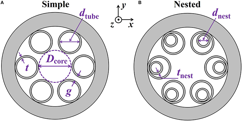
Figure 1. Cross sections of (A) a simple and (B) a nested negative curvature fiber.
3. Antiresonance Condition and Confinement Loss
In order to minimize the loss in negative curvature fibers, the wall thickness of the tubes should approximately satisfy an antiresonance condition [33, 34]. As shown schematically in Figure 2, this condition accounts to ensuring that the round trip of the wave in the transverse direction in the glass layer is close to an odd multiple of λ/2, so that destructive interference of the light transmission occurs in the tube walls. As a consequence, light is repelled from tube walls, which reduces both the confinement loss and the impact of the material loss. While the argument that we have given only strictly applies to a planar geometry and not the geometries in Figure 1, computational studies [13, 35, 36] have shown that this condition holds to good approximation in the geometries in Figure 1, and it is not stringent.
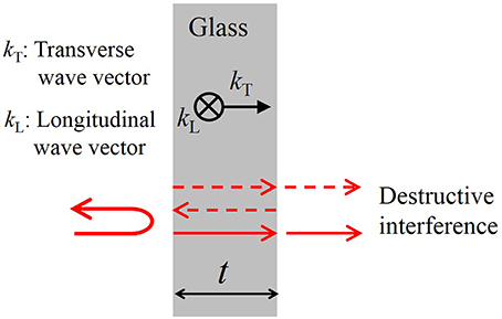
Figure 2. Schematic illustration of the antiresonance condition.
The tube thickness t for both the outer tubes and nested tubes that is required by the antiresonance condition is given by
where n1 and n0 are the real part of refractive indices of the glass and air, λ is the light wavelength, and m is the antiresonance order [33, 34]. We use the second antiresonance transmission band for which m = 2. We ran additional simulations on the first and third transmission bands, and we obtained similar losses to the loss that we obtained using the second antiresonance transmission band [37]. A higher-order antiresonance implies thicker tube wall thickness, especially for shorter wavelengths, which makes fabrication easier; however, the analysis and conclusions in this paper still hold if we use the first or third transmission band. In Figure 3, we use Equation (2) to plot the antiresonant tube thickness as a function of wavelength, λ, and the refractive index, n1. Figure 4 shows the confinement loss of simple and nested negative curvature fibers that are calculated using the antiresonant tube thickness as a function of the wavelength and the refractive index. We assume no material loss in this section, in order to focus on the confinement loss. The core diameter, Dcore, and the minimum gap between tubes, g, are fixed at 60 μm and 10 μm, respectively. The ratio of the diameter of the nested tube to the diameter of the outer tube is fixed at, dnest / dtube = 0.5. We see that the confinement loss increases as the wavelength increases in both simple and nested fibers, which implies that the loss is mainly determined by the wavelength, and the index of refraction has a relatively low impact on the fiber loss.
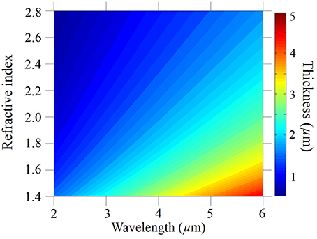
Figure 3. Contour plot of the tube thicknesses that satisfy the antiresonance condition, , where m = 2.
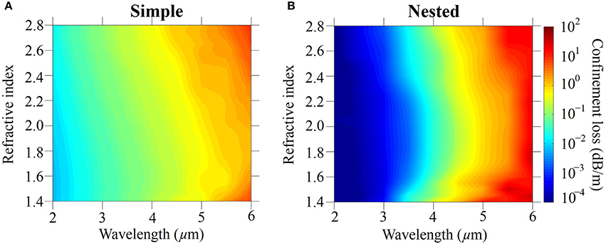
Figure 4. Contour plot of fiber loss in (A) simple and (B) nested negative curvature fibers. No material loss is included.
The normalized mode intensity in both simple and nested negative curvature fibers is shown in Figure 5. Only a quarter of the geometry is used in modeling the fiber because of the symmetry of the fundamental modes [32]. The refractive index and wavelength are 1.45 and 2.00 μm, respectively. We use antiresonant tube wall thicknesses that are given by Equation (2). In both simple and nested negative curvature fibers, the mode field is well-confined in the core.
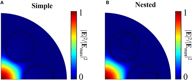
Figure 5. Normalized mode intensity at a wavelength of 2.00 μm in both (A) simple and (B) nested negative curvature fibers.
4. Silica Glass
In this section, we study fiber loss in negative curvature fibers made with silica. Keeping the geometry of the fiber fixed, as shown in Figure 1, we calculate the total fiber loss as a function of both the material loss and the wavelength. The material loss increases from 10−1 dB/m to 105 dB/m and the wavelength increases from 2 μm to 6 μm. The fundamental mode will change as a function of these two parameters, which will in turn change the confinement loss. The total fiber loss is a combination of the material loss and the confinement loss. Since the material loss is not an arbitrary parameter, the value of this plot requires some explanation. As the material loss increases at a fixed wavelength, the total fiber loss will initially be dominated by the confinement loss and will be almost constant and then later will be dominated by the material loss and change proportional to the material loss. By plotting the actually material loss on a contour plot of the total fiber loss as a function of both the material loss and the wavelength, it is possible to immediately determine by visual inspection whether material loss or confinement loss dominates the total fiber loss.
We show the results of this procedure for silica fiber in Figure 6. We denote the region in the parameter space in which confinement loss dominates as region I and the region in which material loss dominates as region II. The two regions are separated by a black dashed curve that is drawn through the points of maximum curvature in the contour plot [38]. We have set the refractive index n1 = 1.45, and we do not include the small effect of dispersion. As noted previously, we use the second transmission band, m = 2, as shown in Equation (2). We set the core diameter Dcore = 60 μm and we set the minimum gap between tubes g = 10 μm. Comparing Figures 6A,B, we first observe that the total fiber loss is smaller below 3.5 μm for the nested fiber than it is for the simple fiber. The reason is that the nested tubes provide a second antiresonant layer and enhance the confinement. However, above 4.5 μm, the loss in the nested fiber is larger than in the simple fiber. The reason is that the diameters of the nested tubes are too small for them to function as antiresonant layers, and they add to the material loss and the total fiber loss. For example, when λ = 5 μm, the inner and outer diameter (din and dout) of the nested tubes, 16.4 μm and 23.6 μm, are only a few times the wavelength. To confirm this point, we show the fiber loss as a function of the diameter of the nested tube, as shown in Figure 7. We fixed Dcore = 60 μm, g = 10 μm, λ = 2 μm, and n1 = 1.45. We also set the material loss equal to zero. We can see that, when the diameter of the nested tube is less than four to five times the wavelength, the fiber confinement loss increases significantly.
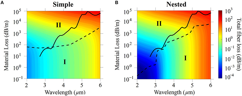
Figure 6. Contour plot of fiber loss in (A) simple and (B) nested negative curvature fibers made with silica glass. The black solid curves show the material loss of silica glass. The black dashed curves separate regions I and II.
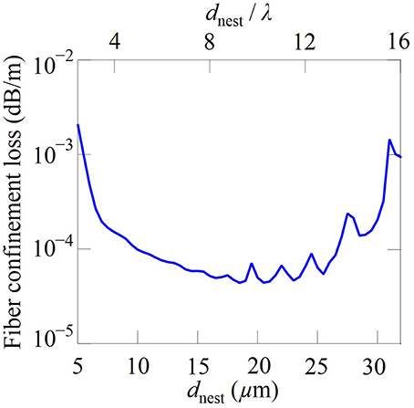
Figure 7. Fiber confinement loss as a function of diameter of the nested tube. No material loss is included. We set λ = 2 μm.
We also plot the material loss of silica [12, 25] using the black solid curve in Figures 6A,B. The high loss bumps in the black solid curve are due to overtones and combination vibrations from the absorption bands at longer wavelengths of 8.9 μm, 12.5 μm, and 21.5 μm [25]. The corresponding simple and nested fiber losses located at the material loss curves are extracted from Figures 6A,B and plotted in Figure 8 using red solid and red dashed curves, respectively. Since most of the mode propagates in air, the bulk material loss is several orders of magnitude higher than the total fiber loss. We also observe that the total fiber loss increases with wavelength. It is lower in the nested fiber than in the simple fiber when the wavelength is less than 3.5 μm. However, when the wavelength is larger than 3.5 μm, nested tubes do not lower the total fiber loss, and the losses indicated by the red solid curve and red dashed curve are almost the same.
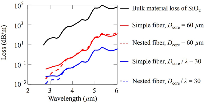
Figure 8. Fiber loss of simple and nested negative curvature fibers made with silica glass.
The core diameter is fixed at 60 μm in Figures 6A,B. At longer wavelengths, it is better to use a larger core in order to lower the fiber loss. Negative curvature fibers have been fabricated using a ratio of the core diameter to the wavelength that varies from 31 to 36 [10–12, 39]. We then study negative curvature fibers with a fixed ratio of the core diameter to the wavelength, Dcore / λ = 30. We can directly extract the total loss from the data in Figures 6A,B by using the constraint Dcore / λ = 30 and the scale invariance of Maxwell's equations [40]. As the wavelength and fiber geometry increase proportionally, the total fiber loss is determined by the material loss of the glass. The corresponding total fiber loss of simple and nested fibers are shown as blue solid and dashed curves in Figure 8, respectively. When the wavelength is larger than 3.5 μm, the bulk material loss is higher than 102 dB/m in region II, and the total fiber losses of the simple and nested fibers are similar and dominated by the material loss. When the wavelength is less than 3.5 μm, the nested fiber has a low confinement loss with an additional antiresonant layer. Hence, the blue dashed curve for the total fiber loss in the nested fiber has a similar shape as the curve for the bulk material loss, as shown in Figure 8.
Overall, with a fixed ratio of Dcore / λ = 30, the simple and nested negative curvature fibers can be used for transmission with a loss around or less than 10−1 dB/m up to a wavelength of around 4.5 μm.
5. Chalcogenide Glasses
In this section, we carry out the same loss analysis on negative curvature fibers made with As2S3 and As2Se3 chalcogenide glasses as what we carried out in Section 4 for silica glass. For As2S3, we have n1 = 2.4 and for As2Se3, n1 = 2.8. The small dispersive contribution is again ignored. The tube wall thickness using Equation (2) in the second antiresonance transmission band m = 2 is again used. Figures 9A,C show the total fiber loss in simple and nested negative curvature fibers, respectively, for As2S3, and Figures 9B,D show the total fiber loss in simple and nested negative curvature fibers for As2Se3. We use a wavelength range of 2 μm to 6 μm in Figure 9. We note however that As2Se3 has a broader transmission window that goes out approximately to 10 μm [41].
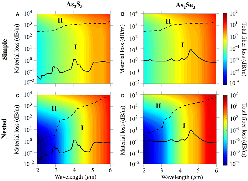
Figure 9. Contour plot of fiber loss in (A) simple and (C) nested negative curvature fibers made with As2S3 chalcogenide glass. Contour plot of fiber loss in (B) simple and (D) nested negative curvature fibers made with As2Se3 chalcogenide glass. The black solid curves show the material loss of chalcogenide glass. The black dashed curves separate regions I and II.
The bulk material loss is shown using black solid curves [41, 42]. In Figures 9A,C, the peaks in the material loss curve of As2S3 at wavelengths of 2.8 μm, 2.92 μm, and 4.05 μm are due to the absorption bands of impurities of H2O, OH, and SH, respectively [43]. In Figures 9B,D, the peak in the material loss curve of As2Se3 at a wavelength of 4.57 μm is due to the H-Se stretching vibration [41, 44]. The three minor peaks at wavelengths of 2.32 μm, 3.55 μm, and 4.15 μm are attributed to the combination and first overtone of the H-Se stretching vibration at 4.57 μm [41, 44]. In Figure 9, just as in the case of silica fibers, two regions, denoted I and II, are separated by a black dashed curve in which confinement loss and material loss dominate, respectively. In contrast to silica fibers, we see that confinement loss dominates the total fiber loss at all wavelengths.
With a fixed Dcore = 60 μm, the corresponding simple and nested fiber loss located at the material loss curves are extracted from Figures 9A,C and plotted in Figure 10A using red solid and red dashed curves, respectively. The total fiber loss increases almost linearly and has no similarity with the shape of the material loss curve of As2S3, which is consistent with the observation that the total fiber loss is dominated by the confinement loss. The total fiber loss is lower in the nested fiber than in the simple fiber when the wavelength is less than 4.5 μm. The total fiber loss is a little higher in the nested fiber than in the simple fiber when the wavelength is larger than 4.5 μm, because, just as the case in silica fibers, the diameter of the nested tube is too small for it to act effectively as an antiresonant layer.
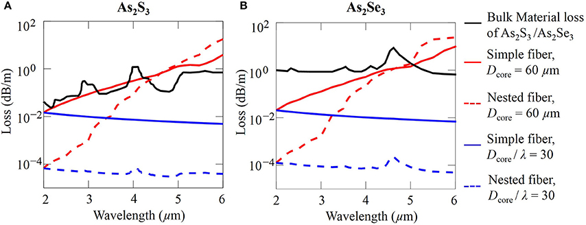
Figure 10. Fiber loss of simple and nested negative curvature fibers made with (A) As2S3 chalcogenide, and (B) As2Se3 chalcogenide glasses.
When the ratio of the core diameter to the wavelength, Dcore / λ = 30, the blue solid and dashed curves show respectively the corresponding total fiber loss of simple and nested As2S3 fibers in Figure 10A. When the wavelength increases from 2 to 6 μm, the total fiber loss decreases slightly in the simple fiber, as shown by the blue solid curve. In this case, the material loss of As2S3 chalcogenide glass is in the region I and does not contribute much to the total fiber loss. The imaginary part of the effective index remains almost the same at different wavelengths due to the scale invariance of Maxwell's equations [40]. The total fiber loss is then slightly lower for a longer wavelength according to Equation (1). On the other hand, the blue dashed curve is two orders of magnitude lower than the blue solid curve, which shows that the nested fiber has a much lower confinement loss due to the additional antiresonant layers. In Figure 10B, we show the figure for As2Se3 that corresponds to Figure 10A. The results are similar to what we observe for As2S3 fibers. With Dcore = 60 μm, the total loss is dominated by confinement loss, and nested fibers have a slightly higher loss than simple fibers beyond 5 μm. When Dcore / λ = 30, total fiber loss decreases slightly as wavelength increases, and the material loss does not contribute much to the total fiber loss.
6. Comparison and Analysis
In this section, we will compare the performance of negative curvature fibers made with silica and chalcogenide glasses. Figures 11A,B show a comparison of simple and nested negative curvature fibers made with silica, As2S3 chalcogenide, and As2Se3 chalcogenide glasses between a wavelength range of 2 μm and 6 μm. The ratio of the core diameter to the wavelength is fixed at Dcore / λ = 30. In simple negative curvature fibers made with silica, the fiber loss increases after 3.5 μm due to the material loss. For wavelengths shorter than 4.5 μm, the loss of silica negative curvature fiber is around or less than 10−1 dB/m. These fibers are easier to fabricate than chalcogenide fibers and should be used at wavelengths below 4.5 μm. At wavelengths that are longer than 4.5 μm, As2S3 chalcogenide or As2Se3 chalcogenide fibers are preferred because their loss is at least one order of magnitude less than that of silica fibers. In nested negative curvature fibers, fibers made with chalcogenide glasses have a loss much lower than that of fibers made with silica. However, due to the fabrication advantages, it is still preferable to use silica fibers at wavelengths below 4.5 μm.
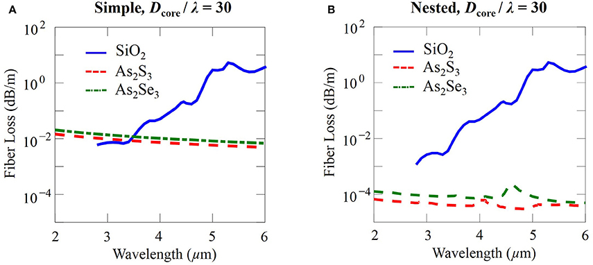
Figure 11. Fiber loss of (A) simple and (B) nested negative curvature fibers made with silica, As2S3 chalcogenide, and As2Se3 chalcogenide glasses with Dcore / λ = 30.
Figures 12A,B show a comparison of simple and nested negative curvature fibers made with silica, and chalcogenide glasses with a fixed core diameter of 60 μm between a wavelength range of 2 μm and 6 μm. We arrive again at the same conclusion as when we fixed Dcore / λ = 30. It is preferable to use silica glass below 4.5 μm, and it is preferable to use chalcogenide glasses above this wavelength.
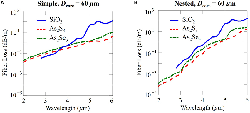
Figure 12. Fiber loss of (A) simple and (B) nested negative curvature fibers made with silica, As2S3 chalcogenide, and As2Se3 chalcogenide glasses with a fixed core diameter of Dcore = 60 μm.
7. Conclusion
We computationally study the fiber loss in simple and nested negative curvature fibers made with silica, As2S3 chalcogenide, and As2Se3 chalcogenide glasses. There is no significant difference in loss for fibers using materials with different refractive indices if no material loss is considered. With a fixed core diameter to wavelength ratio of Dcore / λ = 30 or a fixed core diameter Dcore = 60 μm, silica negative curvature fibers should be used for either simple or nested negative curvature fibers at wavelengths that are shorter than 4.5 μm. The achievable total fiber loss is around 10−1 dB/m or less in this wavelength range, and silica fibers are easier to fabricate. For wavelengths that are longer than 4.5 μm, As2S3 or As2Se3 chalcogenide negative curvature fibers should be used because their total fiber loss is one or more orders of magnitude lower than the total fiber loss in silica fibers. In nested negative curvature fibers, fibers made with chalcogenide glasses have losses that are lower than the losses in fibers made with silica at wavelengths that are longer than 2 μm. However, silica fibers should still be used at wavelengths less than 4.5 μm since their total fiber loss is still around or less than 10−1 dB/m, and they are easier to fabricate. Nested tubes do not decrease the total fiber loss when the diameters of the nested tubes are less than 4–5 times the wavelength because the nested tubes no longer act as an antiresonant layer. This comparative study for negative curvature fibers shows that it is advantageous to use silica glass in negative curvature fibers below 4.5 μm, and it is advantageous to use chalcogenide glasses at longer wavelengths.
Author Contributions
All authors listed, have made substantial, direct and intellectual contribution to the work, and approved it for publication.
Conflict of Interest Statement
The authors declare that the research was conducted in the absence of any commercial or financial relationships that could be construed as a potential conflict of interest.
Acknowledgments
This research was supported in part by funds from the Vice Provost for Research at Baylor University. Work at UMBC was supported by the Naval Research Laboratory. A portion of this work was carried out while one of the authors (CRM) was a guest at the Max Planck Institute for the Science of Light with support from the Alexander von Humboldt Foundation.
References
1. Knight JC, Broeng J, Birks TA, Russell PSJ. Hollow-core PCF for guidance in the mid to far infra-red. Science (1998) 282:1476–8. doi: 10.1126/science.282.5393.1476
2. Broeng J, Barkou SE, Søndergaard T, Bjarklev A. Analysis of air-guiding photonic bandgap fibers. Opt Lett. (2000) 25:96–8. doi: 10.1364/OL.25.000096
3. Pearce G, Pottage J, Bird D, Roberts P, Knight JC, Russell PSJ. Hollow-core PCF for guidance in the mid to far infra-red. Opt. Express (2005) 13:6937–46. doi: 10.1364/OPEX.13.006937
4. Russell PSJ. Photonic-crystal fibers. J Lightwave Technol. (2006) 24:4729–49. doi: 10.1109/JLT.2006.885258
5. Hu J, Menyuk CR. Leakage loss and bandgap analysis in air-core photonic bandgap fiber for nonsilica glasses. Opt Express (2007) 15:339–49. doi: 10.1364/OE.15.000339
6. Poletti F, Petrovich MN, Richardson DJ. Hollow-core photonic bandgap fibers: technology and applications. Nanophotonics (2013) 2:315–40. doi: 10.1515/nanoph-2013-0042
7. Petrovich MN, Amezcua-Correa R, Broderick NG, Richardson DJ, Delmonte T, Watson MA, et al. “Photonic bandgap fibres for broadband transmission of SWIR wavelengths,” In: Electro Magnetic Remote Sensing (EMRS) Defense Technology Centre (DTC) Conference, paper B19, (Edinburgh) (2006).
8. Wang Y, Couny F, Roberts PJ, Benabid F. “Low loss broadband transmission in optimized core shape Kagome hollow core PCF,” In: Conference on Lasers and Electro-Optics/Quantum Electronics and Laser, Postdeadline Papers, paper CPDB4 (San Jose, CA: Optical Society of America) (2010).
9. Wang Y, Wheeler NV, Couny F, Roberts PJ, Benabid F. Low loss broadband transmission in hypocycloid-core Kagome hollow-core photonic crystal fiber. Opt Lett. (2011) 36:669–71. doi: 10.1364/OL.36.000669
10. Pryamikov AD, Biriukov AS, Kosolapov AF, Plotnichenko VG, Semjonov SL, Dianov EM. Demonstration of a waveguide regime for a silica hollow-core microstructured optical fiber with a negative curvature of the core boundary in the spectral region > 3.5 μm. Opt Express (2011) 19:1441–8. doi: 10.1364/OE.19.001441
11. Yu F, Wadsworth WJ, Knight JC. Low loss silica hollow core fibers for 3–4 μm spectral region. Opt Express (2012) 20:11153–8. doi: 10.1364/OE.20.011153
12. Kolyadin AN, Kosolapov AF, Pryamikov AD, Biriukov AS, Plotnichenko VG, Dianov EM. Light transmission in negative curvature hollow core fiber in extremely high material loss region. Opt Express (2013) 21:9514–9. doi: 10.1364/OE.21.009514
13. Poletti F. Nested antiresonant nodeless hollow core fiber. Opt Express (2014) 22:23807–28. doi: 10.1364/OE.22.023807
14. Kosolapov AF, Pryamikov A, Alagashev G, Kolyadin A, Biriukov A, Dianov E. “Negative curvature hollow-core fibers (NCHCFs) for mid-IR applications,” In: Advanced Photonics 2014, OSA Technical Digest (Online), Paper SoTu2B.3. (Barcelona: Optical Society of America) (2014).
15. Wei C, Kuis RA, Chenard F, Menyuk CR, Hu J. Higher-order mode suppression in chalcogenide negative curvature fibers. Opt Express (2015) 23:15824–32. doi: 10.1364/OE.23.015824
16. Hassan MRA, Yu F, Wadsworth WJ, Knight JC. Cavity-based mid-IR fiber gas laser pumped by a diode laser. Optica (2016) 3:218–21. doi: 10.1364/OPTICA.3.000218
17. Wei C, Menyuk CR, Hu J. Bending-induced mode non-degeneracy and coupling in chalcogenide negative curvature fibers. Opt Express (2016) 24:12228–39. doi: 10.1364/OE.24.012228
18. Shiryaev VS, Kosolapov AF, Pryamikov AD, Snopatin GE, Churbanov MF, Biriukov AS, et al. Development of technique for preparation of As2S3 glass preforms for hollow core microstructured optical fibers. J Optoelectron Adv Mater. (2014) 16:1020–5.
19. Shiryaev VS. Chalcogenide glass hollow core microstructured optical fibers. Front Mater. (2015) 2:24. doi: 10.3389/fmats.2015.00024
20. Kosolapov AF, Pryamikov AD, Biriukov AS, Shiryaev VS, Astapovich MS, Snopatin GE, et al. Demonstration of CO2-laser power delivery through chalcogenide-glass fiber with negative-curvature hollow core. Opt Express (2011) 19:25723–8. doi: 10.1364/OE.19.025723
21. Yeh P, Yariv A, Hong CS. Electromagnetic propagation in periodic stratified media. I. General theory. J Opt Soc Am. (1977) 67:423–38. doi: 10.1364/JOSA.67.000423
22. Hu J, Menyuk CR. Understanding leaky modes: slab waveguide revisited. Adv Opt Photonics (2009) 1:58–106. doi: 10.1364/AOP.1.000058
23. Belardi W, Kinght JC. “Negative curvature fibers with reduced leakage loss,” In: Proceedings of Optical Fiber Communication Conference (Optical Society of America, 2014), Paper Th2A.45 (San Francisco, CA) (2014).
24. Michieletto M, Lyngsø JK, Jakobsen C, Lægsgaard J, Bang O, Alkeskjold TT. Hollow-core fibers for high power pulse delivery. Opt Express (2016) 24:7103–19. doi: 10.1364/OE.24.007103
25. Kryukova EB, Plotnichenko VG, Dianov EM. IR absorption spectra in high-purity silica glasses fabricated by different technologies. Proc SPIE (2000) 4083:71–88. doi: 10.1117/12.385657
26. Yu F, Knight JC Spectral attenuation limits of silica hollow core negative curvature fiber. Opt Express (2013) 21:21466–71. doi: 10.1364/OE.21.021466
28. Xia C, Kumar M, Kulkarni OP, Islam MN, Terry FJ. Mid-infrared supercontinuum generation to 4.5 μm in ZBLAN fluoride fibers by nanosecond diode pumping. Opt Lett. (2006) 31:2553–5. doi: 10.1364/OL.31.002553
29. Ebendorff-Heidepriem H, Kuan K, Oermann MR, Knight K, Monro TM. Extruded tellurite glass and fibers with low OH content for mid-infrared applications. Opt Mater Express (2012) 2:432–42. doi: 10.3389/10.1364/OME.2.000432
30. Tao G, Ebendorff-Heidepriem H, Stolyarov AM, Danto S, Badding JV, Fink Y, et al. Infrared fibers. Adv Opt Photon. (2015) 7:379–458. doi: 10.1364/AOP.7.000379
31. Saitoh K, Koshiba M. Leakage loss and group velocity dispersion in air-core photonic bandgap fibers. Opt Express (2003) 11:3100–9. doi: 10.1364/OE.11.003100
32. White TP, Kuhlmey BT, McPhedran RC, Maystre D, Renversez G, Martijn de Sterke C, et al. Multipole method for microstructured optical fibers. I. Formulation. J Opt Soc Am B (2002) 19:2322–30. doi: 10.1364/JOSAB.19.002322
33. Duguay MA, Kokubun Y, Koch TL, Pfeiffer L. Antiresonant reflecting optical waveguides in SiO2-Si multilayer structures. Appl Phys Lett. (1986) 49:13–5. doi: 10.1063/1.97085
34. Litchinitser NM, Abeeluck AK, Headley C, Eggleton BJ. Antiresonant reflecting photonic crystal optical waveguides. Opt Lett. (2002) 27:1592–4. doi: 10.1364/OL.27.001592
35. Vincetti L, Setti V. Waveguiding mechanism in tube lattice fibers. Opt Express (2010) 18:23133–46. doi: 10.1364/OE.18.023133
36. Yu F, Knight JC. Negative curvature hollow-core optical fiber. IEEE J Sel Top Quantum Electron. (2016) 22:4400610. doi: 10.1109/JSTQE.2015.2473140
37. Wei C, Menyuk CR, Hu J. Impact of cladding tubes in chalcogenide negative curvature fibers. IEEE Photon J. (2016) 8:2200509. doi: 10.1109/JPHOT.2016.2577711
38. Thomas GB, Finney RL. Calculus and Analytic Geometry, 9th Edn. Boston, MA: Addison-Wesley (1995).
39. Belardi W, Knight JC. Hollow antiresonant fibers with low bending loss. Opt Express (2014) 22:10091–6. doi: 10.1364/OE.22.010091
40. Joannopoulos JD, Johnson SG, Winn JN, Meade RD. Photonic Crystals: Molding the Flow of Light. Princeton, NJ: Princeton University Press (2011).
41. Nguyen VQ, Sanghera JS, Pureza PC, Kung FH, Aggarwal ID. Fabrication of arsenic selenide optical fiber with low hydrogen impurities. J Am Ceram Soc. (2002) 85:2849–51. doi: 10.1111/j.1151-2916.2002.tb00541.x
42. Sanghera JS, Shaw LB, Pureza P, Nguyen VQ, Gibson D, Busse L, et al. Nonlinear properties of chalcogenide glass fibers. Int J Appl Glass Sci. (2010) 1:296–308. doi: 10.1111/j.2041-1294.2010.00021.x
43. Churbanov MF. Recent advances in preparation of high-purity chalcogenide glasses in the USSR. J Non-Cryst Solids (1992) 140:324–30. doi: 10.1016/S0022-3093(05)80790-2
Keywords: negative curvature fibers, refractive index, fiber loss, material loss, confinement loss, mid-IR
Citation: Wei C, Hu J and Menyuk CR (2016) Comparison of Loss in Silica and Chalcogenide Negative Curvature Fibers as the Wavelength Varies. Front. Phys. 4:30. doi: 10.3389/fphy.2016.00030
Received: 13 May 2016; Accepted: 04 July 2016;
Published: 22 July 2016.
Edited by:
Andrey D. Pryamikov, Fiber Optics Research Center of Russian Academy of Sciences, RussiaReviewed by:
Raul J. Martin-Palma, Universidad Autonoma de Madrid, SpainJunichi Fujikata, Photonics Electronics Technology Research Association, Japan
Copyright © 2016 Wei, Hu and Menyuk. This is an open-access article distributed under the terms of the Creative Commons Attribution License (CC BY). The use, distribution or reproduction in other forums is permitted, provided the original author(s) or licensor are credited and that the original publication in this journal is cited, in accordance with accepted academic practice. No use, distribution or reproduction is permitted which does not comply with these terms.
*Correspondence: Jonathan Hu, jonathan_hu@baylor.edu