Herbert: design and realization of a full-sized anthropometrically correct humanoid robot
 Brennand Pierce
 Gordon Cheng
- Institute for Cognitive Systems, Technische Universität München, Munich, Germany
In this paper, we present the development of a new full-sized anthropometrically correct humanoid robot Herbert. Herbert has 33 DOFs: (1) 29 active DOFs (2 × 4 in the legs, 2 × 7 in the arms, 4 in the waist and 3 in the head) and (2) 4 passive DOFs (2 × 2 in the ankles). We present the objectives of the design and the development of our system, the hardware (mechanical, electronics) as well as the supporting software architecture that encompasses the realization of the complete humanoid system. Several key elements, that have to be taken into account in our approach to keep the costs low while ensuring high performance, will be presented. In realizing Herbert we applied a modular design for the overall mechanical structure. Two core mechanical module types make up the main structural elements of Herbert: (1) small compact mechanical drive modules and (2) compliant mechanical drive modules. The electronic system of Herbert, which is based on two different types of motor control boards and an FPGA module with a central controller, is discussed. The software architecture is based on ROS with a number of sub-nodes used for the controller. All these supporting components have been important in the development of the complete system. Finally, we present results showing our robot’s performances: demonstrating the behavior of the compliant modules, the ability of tracking a desired position/velocity as well as a simple torque controller. We also evaluate our custom communication system. Additionally, we demonstrate Herbert balancing and squatting to show its performance. Moreover, we also show the simplicity of the higher level supporting software framework in realizing new behaviors. All in all, we show that our system is compact and able to achieve comparable human performances and has human proportions while being low cost.
Introduction
Over the past two decades, a number of full-sized humanoid robots have been designed and realized: Hubo (Park et al., 2005), Honda P2/P3 (Hirai et al., 1998), HRP-series (Kaneko et al., 2008), CB (Cheng et al., 2007), LOLA (Lohmeier et al., 2009), TORO iteOtt2010 and ARMAR-4 (Asfour et al., 2013), just to name a few. All these humanoid robots are commonly human in size and achieve similar or greater human performance. However, all of these humanoid robots suffer from one common drawback: their high costs, which are all in the hundreds of thousands of Euros (ranging from €200 K to €1 M). This being one of the main reasons holding back humanoid robots from leaving the high-end laboratories and becoming more widely used, and even 1 day being part of everyday life. The popularity of the humanoid robot NAO (Gouaillier et al., 2009), which is small at 0.57 m, weighs 4.5 kg, and is low cost, has shown that an inexpensive platform can help to make humanoid research more widely accessible to a larger audience from universities to high schools. Thus, we have been designing a full-sized humanoid robot that has similar physical specifications as current full-sized humanoid robots, but with the main objective of making it affordable.
The cost of the actuation mechanism is one of the most costly components on any humanoid robot. For instance, in hydraulic humanoid robots (Cheng et al., 2007; Alfayad et al., 2011), the high costs are created by the servo valves and the high machining tolerances associated with the pistons; whereas in electric humanoid robots, the main costs are in the motors, gearboxes, and motor controllers. In our current approach, we have elected to focus on electric actuated humanoid robots, as we believe that this approach provides us with the best opportunity of making a full-sized humanoid robot at the lowest price while at the same time keeping the same physical performance that other robots possess. Looking over the classic design practice of some of the current generation of humanoid robots, we can identify key aspects that can be improved. Firstly, we set out to replace the Harmonic drives that are used in most high-performance electric humanoid robots, such as HUBO (Oh et al., 2006), HRP-series (Kaneko et al., 2008), TORO (Ott et al., 2010), iCub (Parmiggiani et al., 2012), and ARMAR-4 (Asfour et al., 2013). Secondly, we need to examine the power and control electronics followed by the mechanical design with the aim to reduce the costs and simplify the design of the overall system.
Compliant joints have shown to be beneficial in humanoid robots (Tsagarakis et al., 2011; Enoch et al., 2012b), therefore we set out to examine the use of compliant joints in a selected number of joints, primarily for the legs. The reason we believe mechanical compliance is important for the humanoid’s legs is the foot placement, which is essential for absorbing the impact forces for actions like walking and jumping (Hurst, 2011). Controlled compliance was also considered but that would not provide us with the performance we needed as the latency from the sensors detecting the impact force to the time of the joint moving would be too long (Pratt and Williamson, 1995). Typically, compliance is added to the joint using “Series Elastic Actuators” (SEA), as introduced by (Pratt and Williamson, 1995) where a spring is placed in-between the motor and the output. This has two advantages: (1) first, it makes measuring forces easier as the measured spring displacement corresponds to the force (2) second, it allows absorption of impact forces and could also be used to store energy. SEA has been successfully implemented in a number of robots (Pratt et al., 2001; Veneman et al., 2006; Hobbelen et al., 2008). Therefore, we wanted to investigate incorporating SEA into the design of our robot.
An extension of compliant actuator research is to add additional hardware to make the compliance adjustable. This means that the controller can select from a very soft to a very hard compliance. This gives the robot the advantage of setting the stiffness to very hard for accurate position tracking or very soft for dealing with impact or safety. Some examples of these humanoid robots are MACCEPA (Vanderborght et al., 2009), Blue (Enoch et al., 2012a), and MABEL (Grizzle et al., 2009). The problem with adjustable compliances is that the mechanical complexity still needs to be solved. Furthermore, two coupled motors, which are used to control the joint position and the stiffness of a single joint, add extra weight, space, and costs. This means that the humanoid robot will require at least twice as many motors and controllers than normal. Currently no full-sized adjustable compliant humanoid robot has been realized with similar capability than the more classical approach. As the extra cost of the motors and mechanical structures goes against our primary goal of a low-cost humanoid robot we discounted variable compliance actuation in our design.
Most traditional humanoid robots control strategies rely on very accurate knowledge about the robot’s dynamics (i.e., kinematics and inertia properties) and its environment, and work with high-gain joint position control. Since the major breakthrough in walking control being the introduction of the “zero moment point” (ZMP) (Vukobratović and Borovac, 2004), ZMP was used in the design and control of a number of high performance biped robots (Hirai et al., 1998; Park et al., 2005; Kaneko et al., 2008). The main principle of ZMP is that its moment of inertia should be kept in its support polygon, which is normally the supporting foot. Robots like the HRP-series, Hubo, or LOLA are classed as stiffed fully actuated robots, where the structure and actuation system are rigid with the only compliant element in the sole of the foot. These robots all require very accurate control of the joint angles and velocities. Hence, torque-controlled robots have become more attractive in recent years because of the key features of safe interaction with the environment and humans (Haddadin et al., 2013), compliant behavior, and the ability to directly control the forces within the controller. CB (Cheng et al., 2007) and TORO (Ott et al., 2010) are two examples of full-sized humanoids robots, which are both fully force-controllable.
There has been three humanoid robots that have the primarily design goal of being anthropometrically correct. The first humanoid is HRP-4C (Kaneko et al., 2009) which is based on an average young Japanese female. This humanoid was designed for the entertainment industry such as a fashion model or the master of ceremony. So the hands and head of the robot were designed to be as life like as possible with realistic skin. The second humanoid is WABIAN-2 (Aikawa et al., 2006). This humanoid was designed to help researchers study rehabilitation and welfare instruments. The WABIAN-2 researchers had three reasons that they felt an anthropometrically correct humanoid is beneficiary. First, they hypothesized that measuring the angle and torques at the joints, when the robot used a device, could be measured more easily compared to the corresponding values from a human subject. Second, experiments used by humanoids could help identify defects in humans from an engineering point of view. Third, humanoids could replace people in dangerous situations. Last but not least, the third humanoid PETMAN (Nelson et al., 2012) by Boston Dynamics. This humanoid was designed to test chemical protective clothing. This means that PETMAN had to have human-like strength, speed, and motion while wearing human clothing, including footwear.
Here we outline the key design requirements of Herbert Figure 1A. It has been designed to perform a wide range of human tasks, therefore, it has been designed to be anthropometrically correct. To achieve this goal, the robot has to have the same proportions and weight as a real human (Tilley, 2002), as this simplifies direct mapping of human tasks onto the robot. It can then be used for different tasks like in teaching scenarios, testing prosthesis and devices for disabled people or how to be better able to interact within human environments. This leads to a list of requirements for our new humanoid robot:
• Human weight;
• Affordability;
• Compliant and back-drivable joints;
• Anthropometrically correct;
• Torque controllability;
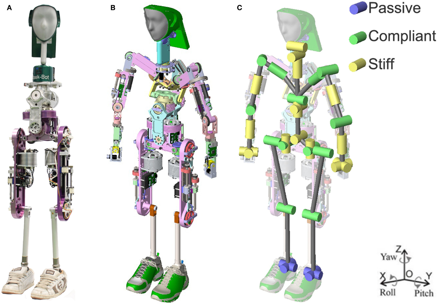
Figure 1. (A) Photo of the current state of Herbert, as used in the physical interaction results section. (B) CAD model of Herbert. (C) The 33 DOFs of the humanoid robot: active (29 DOFs): 2 × 1 DOFs knees, 2 × 3 DOFs hips, 3 DOFs neck, 4 DOFs waist, 7 DOFs arms; passive (4 DOFs): 2× ankles. The purple DOFs are the passive prosthesis. The green DOFs are the compliant leg joints and the yellow are the low cost stiff joints.
General Overview of Herbert’s Design
One of our main goals for Herbert was to design a full-sized humanoid robot that is anthropometrically correct with the size and weight of a 1 percentile adult male (Tilley, 2002). This means that the limbs of the robot should be similar in length and the joint position to be as close as possible to a real human. Using data from Tilley (2002), we were able to define the measurements for the length and joint position. Figure 1B shows the final completed computer-aided design (CAD) of Herbert and the kinematic structure in Figure 1C. To validate Herbert’s proportions with respect to 1 percentile adult male, we super-imposed and scaled the CAD model over the measurement diagram from (Tilley, 2002), as shown in Figure 2. From this, it is clear to see that Herbert is matching very closely to human proportions. The only exception from our anthropometrically correct approach is the shoulders which we required slightly wider and higher. After simulating the model we found that the wider shoulders helped to prevent kinematic singularity and self-collisions with its chest. We needed to raise the shoulders so that we could accommodate the compliant joint modules due to space constraints. As mentioned, all major limbs have the same length as the real human. We have also made sure that all the joints are inline on the sagittal plane. Again, our analyses show that inline shoulders would resulted in a larger working volume, and in order to prevent kinematic singularities they are angled at 20° forward. Hence, Herbert’s shoulders are not inline on the sagittal plane.
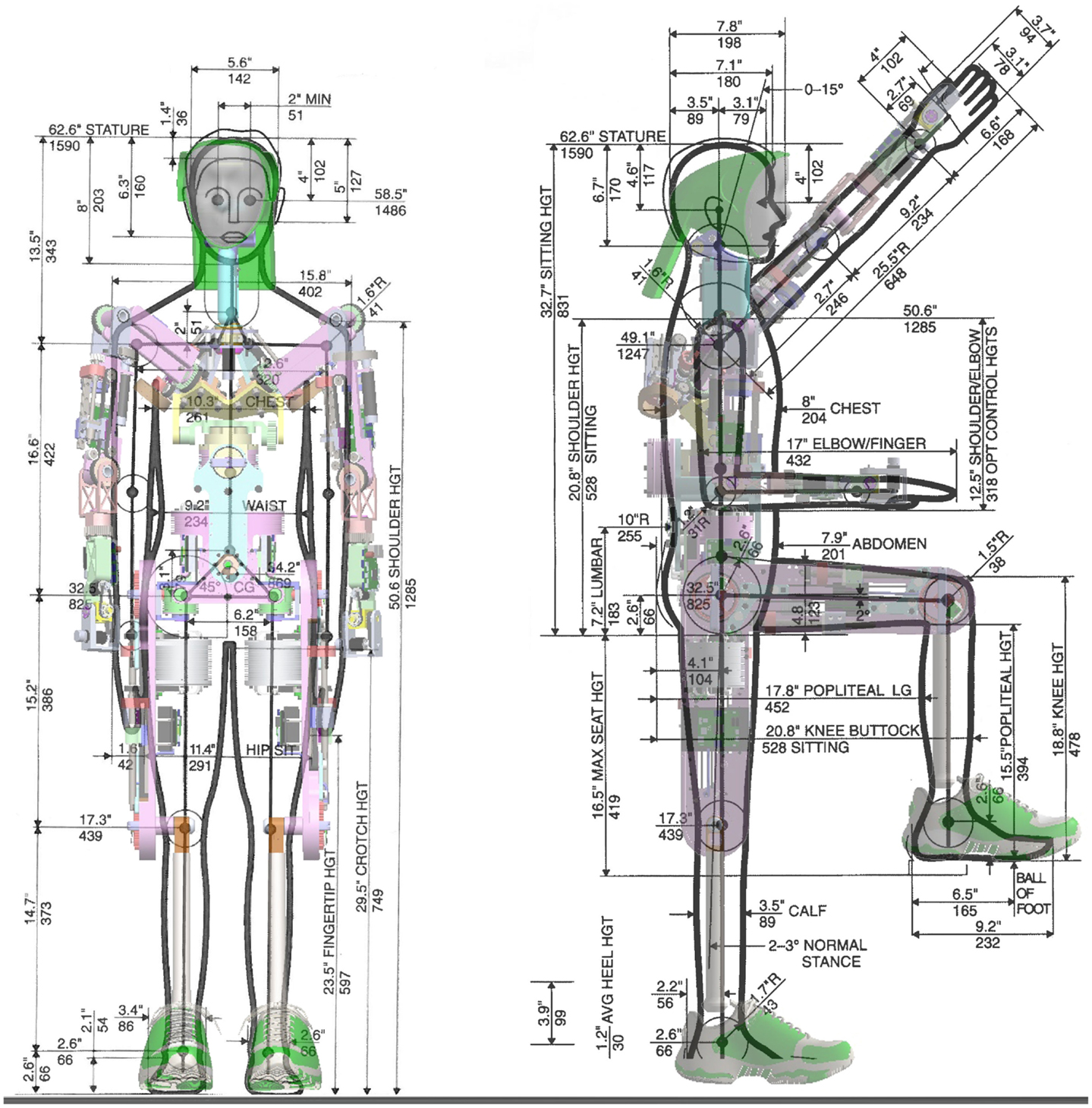
Figure 2. The human proportion of Herbert: all the major joints are in their anthropometrically correct position, we used a 1 percentile full size human man.
One of the most important physical properties of a humanoid are its weight and mass distribution, where it is desirable that the CoM of each limb is as close to the axis of motion. To achieve this, we aimed to place the heaviest components of each limb, which in this case are the motors, as high as we could within the limb. The resulting CoM of each limb are shown in Figure 3A where the gray spheres are volumetrically proportional to the mass of the limb segment and the CoM of the complete humanoid is shown at the waist. For comparison to a real human, we used data from (Drillis et al., 1964) and (Armstrong et al., 1988) to calculate the CoM of each limb of a real 1 percentile adult male. As displayed in Figure 3B, the CoM of the human is also shown at the waist. As it can be seen, the mass distributions are very similar between our robot and the human. Herbert’s mass is very evenly distributed symmetrically apart for his chest where the CoM is to the right by 12 mm due to the chest pitch joint drive mechanism not being centered due to mechanical constraints. Table 1 shows that apart from the lower leg, which is a light weight prosthetics ankle that will be discussed below, the mass of each limb segments in kilograms is very similar in comparison to a 1 percentile adult male. As Herbert does not have onboard batteries presently the chest is also 6.9 kg lighter. From the same table, we present also the location of the limb segments CoM from the sole. This shows that the CoM of each segment is comparable to that of a human. The only major variation is the head as the human head CoM is much higher. As a human head contains our brain, Herbert’s head is hollow which means that its neck is the predominated mass. Herbert’s and a real human’s complete CoM are in a very similar position at the waist: Herbert’s CoM is 907 mm from the ground compared to 869 mm for a real human person. The complete CoM is also very close to the inline joint axis in the sagittal plane and only 0.8 mm to the rear of Herbert. In the frontal plane it is 3.5 mm to the right due to the chest as discussed earlier.
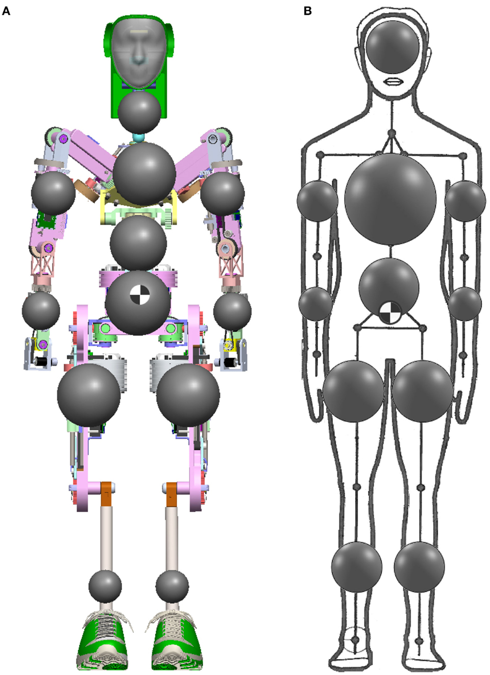
Figure 3. (A) The mass distribution of Herbert where the volume of the dark spheres are proportional to the mass. (B) The mass distribution of a human.
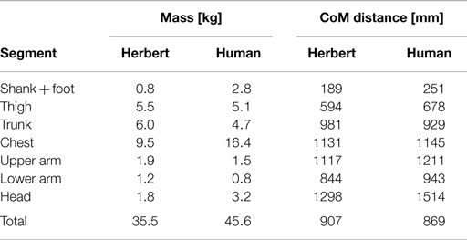
Table 1. The mass of each segment of Herbert compared to a human and the distance from the sole to the center of mass of each segment.
For the mechanical structure, we designed two types of joint actuation mechanisms. The main joint mechanism is compact and cheap while at the same time being functionally similar to the classical harmonic drive or planetary gearbox design. The second type of joint mechanism in our design is a joint with mechanical compliance. We used the compliant mechanism in the legs and arms, so that it can absorb impacts. For the rest of our humanoid robot, we have used the compact design as we believe that the mechanical compliance is not required and therefore software compliance control can be used to save on the overall design complexity and on cost. In Figure 1C, the different mechanisms are presented, as the green DoF is the compliant joint and the yellow DoF is the compact joint mechanisms and the purple is the prosthetic foot. In Table 2, the used types of mechanical mechanisms are shown, all the joints as well as the used reduction ratio, maximum torque, joint range, and the maximum angularly velocity are all presented.
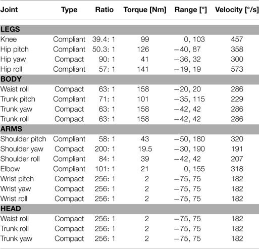
Table 2. Gear ratio, torque, range, and velocity of Herbert’s joints.
Compliant Module
The hip and knees have been designed with a compliant, back drivable mechanism with a replaceable compliant element. The compliant element can be easily replaced in order to allow experiments into how different complaints behave in such tasks as walking and balancing. As we have pointed out earlier, that compliant actuation is very important for walking, especially when it comes to heal strike and the inability of precisely predicting the magnitude and time of the impact forces (Hurst, 2011).
In Figure 4A, the overview of the compliant joint can be seen. (1) are the digital torque sensor electronics; (2) is the pulley, which is also the “compliant element”; (3) is the digital joint encoder; (4) are the strain gages; (5) is the ball screw; (6) is the PMSM motor by Robodrive; and (7) is the motor position encoder. The design is based around the ball screw that drives the pulley belt. We decided to use a ball screw because it is mechanically back drivable, efficient ≥96%, has no-backlash or starting torque, and is also low in cost. We utilized over-sized motors to avoid the need for large gear reductions. With the back drivability and low gear ratio, we believe this will give us much better natural dynamics.
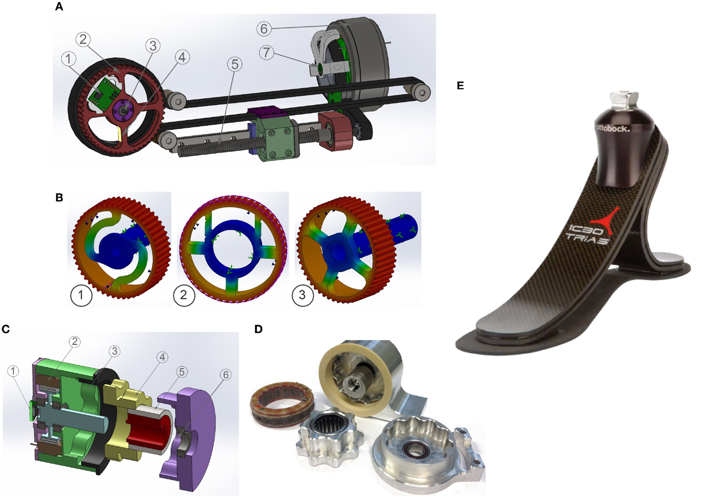
Figure 4. (A) The compliant joint design: 1) are the digital torque sensor electronics; 2) is the pulley, which is also the “compliant element”; 3) is the digital joint encoder; 4) are the strain gages; 5) is the ball screw; 6) is the PMSM motor by Robodrive; and 7) is the motor position encoder. (B) Example of the FEM analysis for the displacement of the pulley. Herbert is currently using example 3. (C) The CAD model of the cycloidal reducer 1) is the motor encoder; 2) is the PMSM motor by Robodrive; 3) is the first-stage ring gear; 4) is the center cycloidal disk; 5) is the eccentric input shaft; and 6) is the output ring gear. (D) An early prototype of the hip jaw joint. (E) The prosthetic foot by Otto Bock used in the foot of Herbert.
The compliant element is directly coupled to the output shaft which has been designed to be easily replaceable. Figure 4B shows different designs that have been tested in CAD using the finite element method (FEM) to compute the theoretical compliance as well as the strength of the component. By using the FEM analysis, we are able to compute the deflection when different torques are applied and also use this data to design the optimum placement for the strain gages to measure the torque on the real robot. In Figure 4B, we experimented with a non-symmetrical design, where one of the spokes was split to increase its length for better placement of strain gages. We are currently using Figure 4B for Herbert.
This mechanism also has a simple safety feature inherited from the design. This is the ability to measure the joint position and velocity as well as the joint torque with two separate sensors, thus being able to detect sensor failures. This error detection is demonstrated in the Results section. To measure the joint position and velocity, we primarily use the joint encoder. But we can also use the motor encoder to work out these values, as we know the overall gear reduction. In order to work out the joint torque, we primarily use the strain gages directly mounted at the joint, and also estimate the torque by looking at the difference between the joint position and the motor encoder position. This difference is due to the compliant element as there is a direct correlation between the joint torque and the difference between these two encoders.
Compact Module
Most full-sized humanoid robots use harmonic drivers for their reduction gearbox as they are small and compact with a high gear ratio like HUBO (Oh et al., 2006), HRP-series (Kaneko et al., 2008), TORO (Ott et al., 2010), iCub (Parmiggiani et al., 2012), and ARMAR-4 (Asfour et al., 2013). Unfortunately, they are very expensive. Planetary gearboxes, on the other hand, have the advantage of low costs but with the drawback of becoming larger and heavier as higher the gear ratio is needed. For our compact design, we elected to use acycloidal reducer instead of the standard method of using harmonic drives. Three advantages are associated with this solution: (1) the first advantage is the cost, as these reducers can be machined at a fraction of the price of a harmonic drive; (2) secondly, it is compact; and (3) finally, the gear housing and teeth can be machined directly into the main joint structure, which leads into an easier incorporation into the overall design.
The input shaft drives an eccentric bearing that in turn drives the cycloidal disk in an eccentric, cycloidal motion. The perimeter of this disk is geared to a stationary ring gear and this connection makes the cycloidal disk rotate at a reduced speed. As we are using a two-stage cycloidal reducer, this central cycloidal disk then mates to the output shaft. The eccentric motion of the disk is not translated to the output shaft so it is spinning centrically. By varying the number of “teeth” in this design, we can obtain a large range of gear ratios for each joint, so that we can find the optimal tradeoff between maximum torque and velocity. This works in a similar way to a harmonic drive but with the main difference that the harmonic drive has a flexible toothed spline that rotates and the cycloidal reducer has a solid gear center. The CAD design can be seen in Figure 4C where (1) is the motor encoder; (2) is the PMSM motor by Robodrive; (3) is the first stage ring gear; (4) is the center cycloidal disk; (5) is the eccentric input shaft; and (6) is the output ring gear. The real version is shown in Figure 4D.
Passive Ankles
To reduce the weight and to simplify the design, we have chosen to use human prosthetics for the feet instead of active ankles. This means that the mass of the overall leg is reduced to 5 kg and that the center of mass is very high, which has added advantage when it comes to dynamic walking. This also means that Herbert can be used in the future to help design and verify prosthetic foot designs. With the reduced need for motors, gearboxes, and electronics, thus, we are able to reduce the overall cost of the legs. Herbert currently uses “1C30 Trias” from Otto Bock, which can be seen in Figure 4E.
Humanoid Head
Robotic heads are normally designed with one primary goal. For example, the “iCub” head (Beira et al., 2006) or the Karlsruhe humanoid head (Asfour et al., 2008) was primarily designed to provide a stable platform for active cameras. Whereas other robotic heads have been designed with the main aim of looking as lifelike as possible, so that the texture of the skin and the mimicking of the muscles are the most important aspect of their design. An example of a head designed primarily to look lifelike is by Hanson Robotics who developed a very realistic head used in the “Albert” version of HUBO humanoid robot (Oh et al., 2006), which utilizes a high number of servo motors used to mimic human muscles and deform its rubbery skin so the head is able to display emotions as well as to articulate the mouth when it speaks. Furthermore, there are examples where the head is used to help in HRI and the primary goal of displaying emotions (Lee et al., 2008). An early example of this type of head is MIT’s KISMET robot (Breazeal and Scassellati, 1999). KISMET had a simple mouth, ears, and eyebrows that were used to display emotions such as happy, sad, or angry. Both “Albert” and KISMET rely heavily on complex mechanical structures, to display these emotions and mouth movements, due to the high number of motors that is needed to modify their facial expressions.
To overcome the need for complex mechanical structures to display emotions and mouth movements, there is an emerging type of robotic head which uses the concept of displaying an avatar instead of relying on a complicated mechanical mechanism. Examples are the “Light Head” by Delaunay et al. (2009, 2011) and the “Curved Screen Face” from Hashimoto and colleagues (Hashimoto and Morooka, 2006), as well as our own robotic head “Mask-Bot” (Kuratate et al., 2011; Pierce et al., 2012). This type of robotic heads has the advantage that the face can be changed and animated fairly easily in software. Also the articulation of the face does not rely on complex mechanical components. Because of the computer-animated face the mouth can be synchronized with the vocal system as well as display emotions.
The head of Herbert was thus primarily developed for HRI and with the secondary goal of being anthropometrically correct. A photo of the resulting head, “Mask-bot 2i”, is illustrated in Figure 5B (Pierce et al., 2012). The main feature of Herbert’s head is the avatar animated onto a mask using a rear projection system. It can be configured with different avatar appearances where eyes and mouth are animated to give a more lifelike appearance. There are four main hardware components used to achieve this: (1) the projector; (2) the optics used to modify the light beam; and (3) the mask (4) the 3 DOF neck.
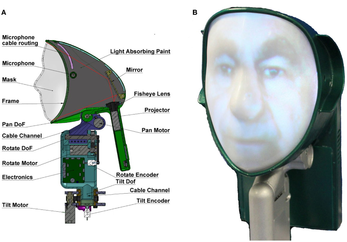
Figure 5. The head of Herbert (A) Cut through of the CAD model of the head. (B) The final head with the avatar projected onto the mask.
As we have stated, one of the main components of the head is the LED projector C112 (Acer Inc.), which is 70 ANSI lumens, has a contrast ratio of 1000:1 and weighs 138 g. For the avatar to be displayed properly, the image needs to go through an optic system to be correctly scaled and angled. Therefore, we decided to use a fisheye lens by “pixeet,” designed for a mobile phone camera with a viewing angle of 180°, the size 30 mm × 17 mm and weight of 18 g. After the lens, the image is angled by a mirror so that we can place the projector in the optimum location with regard to CoM and so the image covers the complete mask without interfering with the neck. The layout of the projection system and the other key components of Herbert’s head can be seen in Figure 5A.
Once we had the projection system for Herbert’s head, we then investigated the possible shape of the mask which the avatar would be projected onto. For easier research, we decided that an interchangeable mask is the best solution for experiments with different contoured surfaces. We tested from very generic versions, where we could project any avatar onto, all the way to a highly specific mask, which matches the projected avatar created from 3D scan data of a specific human subject. This means that we had to design the head with an interchangeable function, which resulted in a frame design where different masks can be attached. To create a generic interchangeable mask (one that can be used with any projected faces), we first developed a face-model which uses a mean average of 124 faces (31 faces from each group: Caucasian male, Caucasian female, Asian male, and Asian female) to create an “average” face Figure 6A.
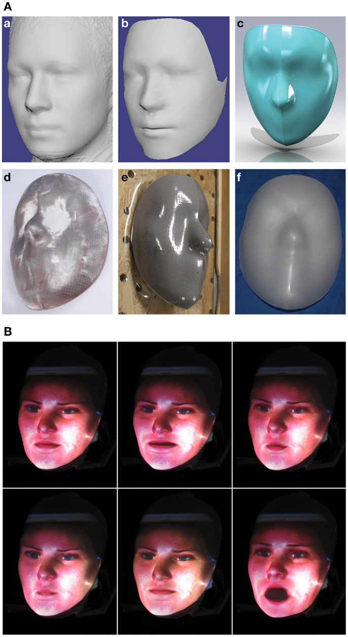
Figure 6. (A) Designing the interchangeable mask: (a) Average face data; (b) The cleaned up dataset; (c) The CAD model of the mask with the correct outer shape to fit into the head’s frame; (d) The 3D-printed mold; (e) The vacuum forming process; (f) The final sprayed mask. (B) Examples of the facial expressions of the avatar projected onto the mask of the head.
Before we have been able to use these data, it needed to be preprocessed to reduce the noise and to trim the excess data Figure 6A. Next we imported these data into CAD software, so that we can turn it into a solid manufacturable object. From our experience with previous generations of rear projected heads we knew that too much detail in the features, for example around the eyes and mouth, do not match a large selection of general avatars. Therefore, we applied a smoothing function to reduce the fine details like in the lip and eye area. Then we trimmed the excess parts, like the ears and the back of the head, and added a rim around the edge so that it fits into the frame of the head Figure 6A.
To manufacture this mask we used vacuum forming based on a mold. To do this we 3D printed this mold out of “Alumide,” which is a plastic material with aluminum dust, using the selective laser sintering process (SLS) Figure 6A. By adding the aluminum dust to the plastic the temperature that the mold can take increases to 172°C, which is needed as the plastic for the mask is heated for the vacuum forming. The mold also needed to be post-processed by polishing the surfaces to avoid that the SLS process leaves a fine sandy surface. The 3D-printed mold was then used on a vacuum table with a 1 mm thick PETG clear plastic which produced a clear mask Figure 6A. The last step was to paint the clear mask with a special rear projection paint by “Goo Systems,” which gave the mask a silver finish and has shown to yield very good results when the avatar is projected onto its surface. The final mask can be seen in Figure 6A.
Once we had the layout of the projector, we then mounted the optical system and the design for the interchangeable mask above a 3 DOF neck and made sure the proportion of the completed head was anthropometrically correct. We based this design on an already existing neck that was based on three brushless BLDC motors coupled to a shaft with pulley belts. This original neck was made from aluminum with a central support structure as can be seen in Figure 7A. But for the production of Herbert’s head, we have elected to completely 3D print all the structural parts for the benefit that the projection system was completely enclosed, thus no light would get behind the mask. It was also beneficial for the neck as we could reduce the cost, weight, and machining time. In Figure 7B, it can be seen how we have gone from an aluminum structural part to a shell-based 3D-printed part using SLS out of nylon. After structural analysis, we could not have done this for all the structural parts of the humanoid but as the head does not receive large external forces we believe that it is the right approach.
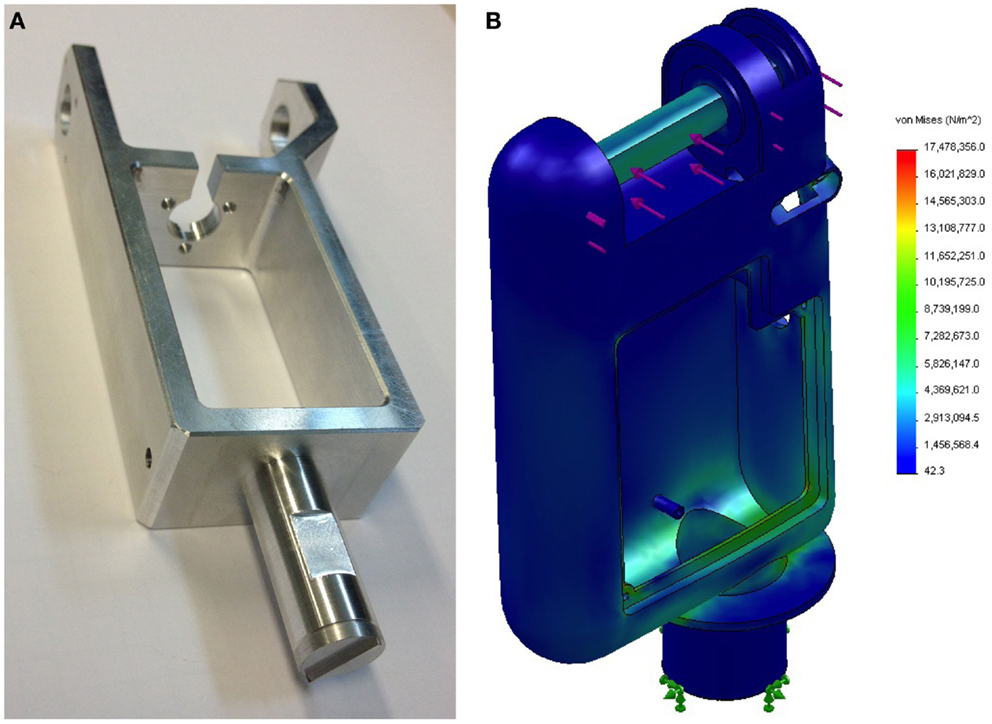
Figure 7. The development of the neck design: (A) Original metal design. (B) New 3D-printed FEM of the neck.
The total weight, including motors, 3D-printed structure, projector system, interchangeable mask, camera, and stereo system, is only 443 g and can be seen in Figure 5A. Figure 6B shows some examples of avatars moving their mouth while speaking. This demonstrates that by using rear projected avatars it is possible to show different facial expressions while being easy in software at the same time. This framework can also be extended to help HRI by displaying emotions.
Mechatronics and Computer Hardware
Electronics
In comparison to other robots, the development of humanoid robotic systems creates unique electrical challenges. First of all, the weight and limited space for the electronics need to be considered. Secondly, the large variety of sensors, which need to be interfaced, have to be taken into account. Lastly, and more importantly, the demand for hard real-time, high-frequency control loops for the predictable control of such complex systems have to be met. Unlike other well-developed robotic systems, like wheeled robots where the controllers and sensors can easily be taken off-the-shelf and then integrated, developers of humanoid systems place a higher priority on compactness and weight. To reduce the amount of electrical cables running from the actuators and sensors to a centralized controller, developers have taken a distributed approach (Nagakubo et al., 2003; Kanehiro et al., 2006; Cheng et al., 2007), where the low level controllers are distributed over the whole humanoid robot. This leads to the benefit of reduced cables as well as compactness. Additionally, when the controllers can be placed in close proximity to the sensors and actuators they control, they have the advantage of minimizing latency between the low-level control loop implemented on the controller. However, it does pose its own problem: How is it possible to handle the vast quantity of information that needs to be communicated to the central processing unit with minimal latency, while also ensuring a fully operational system at the same time?
At the heart of Herbert’s electrical system is a distributed network of FPGA modulars. In our design, every limb on the humanoid robot has a single FPGA module and these modules are networked together in a star formation. These FPGA modules are then individually integrated into a custom carrier board that is tailored for each limb. For Herbert we designed two types of carrier boards consisting of a high power board that is designed to control two joints with 1 kW motors and a low power board designed to control three low powered motors. As each limb has their own sensors and actuation requirements, this star network has a “Central Controller” in the chest of Herbert, which is a combination of an FPGA and duo core ARM processors. These ARM processors are running a “bare metal” code on the first core, which takes care of the low-level, real-time control while Ubuntu runs on the second core. There is an ethernet connection from the central controller to the high-level PCs where all the cognitive processing is computed. For Herbert we designed two main control boards: the first is designed to control two high-powered BLDC motors and the second for controlling three low-powered BLDC motors. Figure 8 presents an overview of the complete electronic system and shows what type of controller is located in each limb. For a more in-depth overview of our complete system, please see Pierce and Cheng (2014). Following, we present the FPGA, high speed communication, the low-power motor control board, the high-power motor control board, and the central controller.
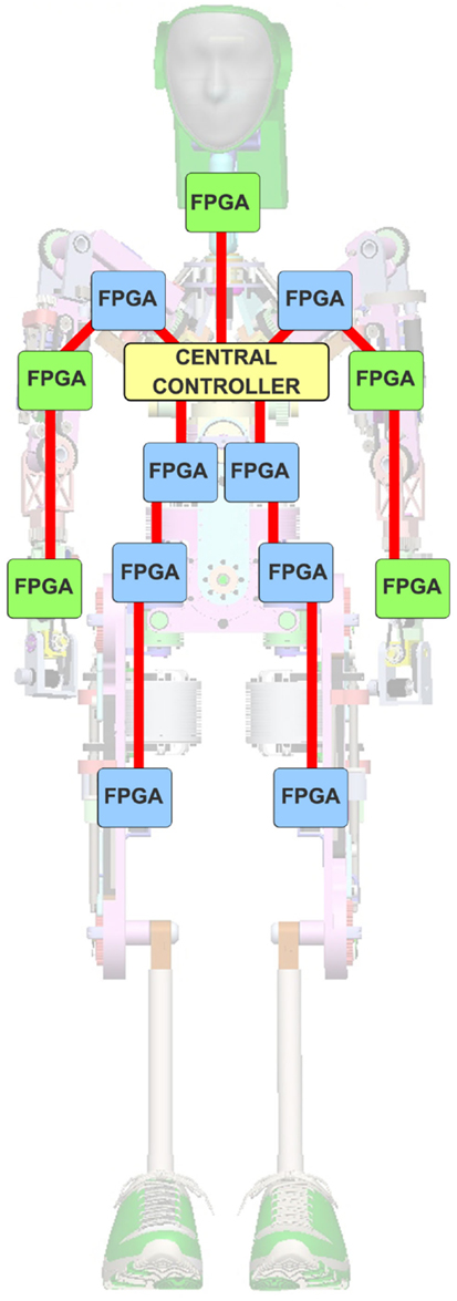
Figure 8. Overall system design. The blue FPGA squares are the high-current BLDC controllers. The green squares are the low amp BLDC controllers. The red lines are bi-directional high speed communication fiber optic channels. The yellow square is the central controller.
FPGA Module
The current version of the FPGA module, which is based around an Xilinx Sparten 6 FPGA, can be seen in Figure 9A. It also has integrated onto the module common components that are desirable for each limb, for example ADC and IMU. This module currently consists of:
• Xilinx Spartan-6 LX45 FPGA.
• 6 axis IMU, MPU-6050.
• 8 Channel ADC, ADS8332.
• 2× Full-duplex 200 Mb/s interconnection.
• 128 Mb SPI Flash.
• 70 I/O, User configurable.
• 17 programable LEDs.
• Size: 35 mm × 35 mm.
• Weight: 8 g.
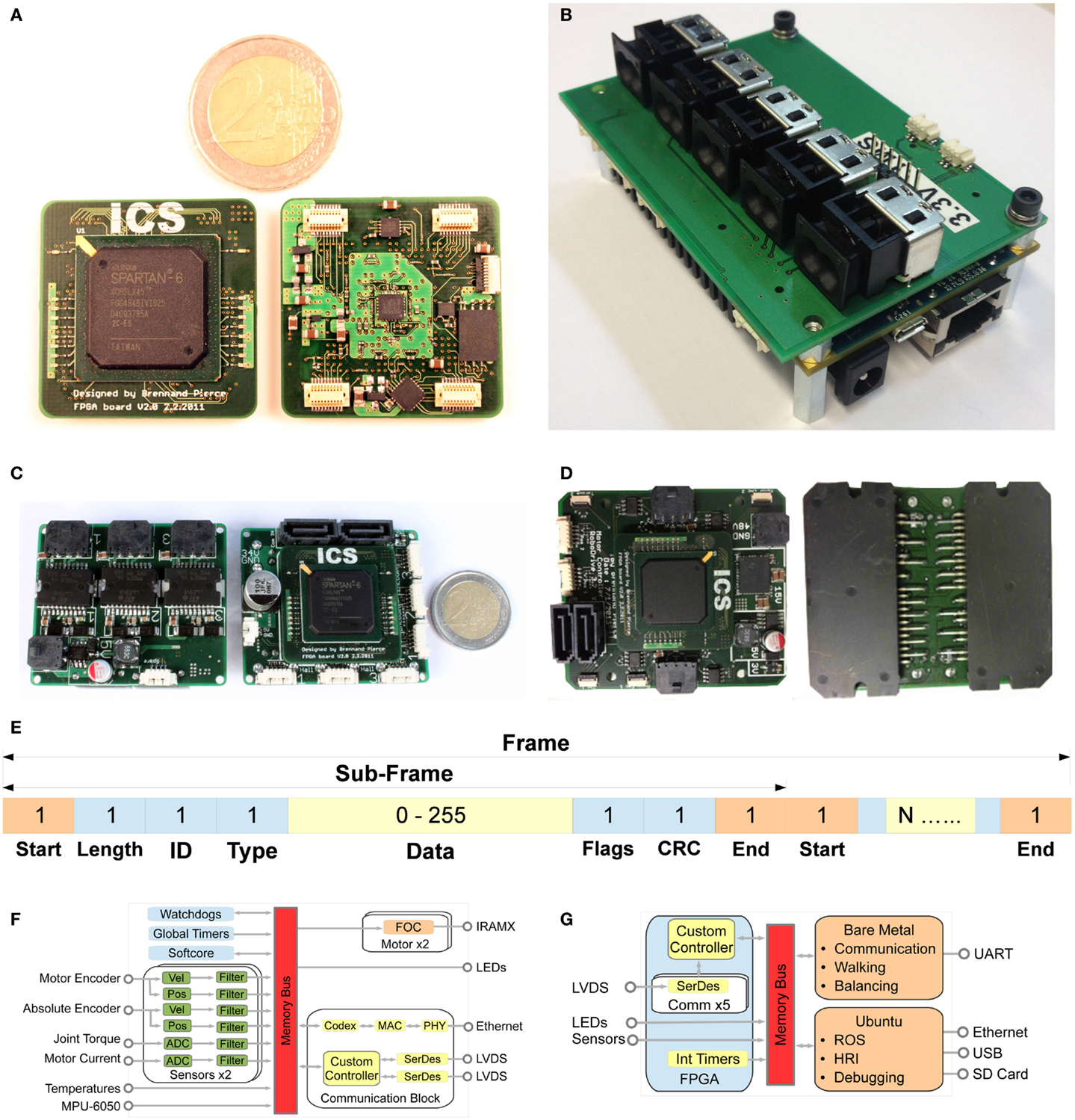
Figure 9. The electrical subsystem for Herbert: (A) FPGA module used in all the sub boards. (B) The central controller with its five fiber optic connectors. (C) Low current motor controller. (D) High-voltage motor controller. (E)The data structure of the high-speed communication frame. Each sub-frame is separated with a unique start and stop word using 8/10b encoding. With a 3 byte header, which consists of 1) The length of the sub-frame 2) The ID of the FPGA module that the sub-frame is for 3) The type, which informs the FPGA about how the data are encoded. The end of the sub-frame is the CRC field used to verify that the data are not corrupted. Then finally the flags which tell the master controller if the sub-frame was processed by the FPGA module and if there were any errors in the system. System overview: (F) Overview of the FPGA code structure for the “High Current BLDC Controller.” (G) Overview of the hardware structure of the central hub. This is based on a Xilinx Zynq-XC7Z020 with two ARM processors.
In order to develop our FPGA module, we simulated the power requirement, the optimal placement of the de-coupling capacitor network, and the rating of the power regulating circuit for a fully configured FPGA. This shows the benefit of modularity, as we only had to simulate and design the circuit once. Due to the nature of the FPGA package (FGG 484), we had to use a six-layered PCB board with 0.1 mm wires to route the FPGA. These requirements make the PCB board expensive to manufacture. Whereas from our experience in designing carrier boards, we know that those high specifications are not required and thus making the PCB boards for the carrier much cheaper. When the module is fully configured it only draws 40 mA.
High-Speed Communication
For high-speed intercommunication among FPGA modules, different standards were examined, including EtherCAT and Powerlink. Both are real-time protocols based on the Ethernet standard. Baglini et al. (2010) provide a good comparison of these two. They concluded that EtherCAT is a better standard for robotic systems. However, our evaluation shows that EtherCAT has some limitations for our requirements. The first is the speed: at the moment EtherCAT is only rated at 100 Mb/s. The second limitation is the physical electronic complexity. EtherCAT’s protocol is based on sending Ethernet telegrams, this means the modules would require 2× PHY Ethernet chips for simultaneous up and down stream traffics. Therefore, we investigated the possibility of using an FPGA on its own for the intercommunication. This produced a simple solution of a direct pin to pin connection using a LVDS and 8/10 b encoding, using a fiber optic cable running at 200 Mb/s. We decide to use a fiber optic cable to minimize packet loss due to the high electrical interfere from the large motors.
The communication network uses the FPGA fabric of the central controller as the master and all the FPGA modules are the slaves. Each module has two Rx and Tx interfaces, via the interfaces, these data are transferred bi-directionally in full duplex configuration. The key to our protocol is that each module starts to forward the packet and appends packets on-the-fly. So after the packet is received, it is put into a FIFO and buffered for 4 bytes and then gets transmitted onto the next module in the network. The complete data structure we call a “frame” and it consists of multiple sub-frames. All the sub-frames are transmitted one after the other and are separated by the reserved words start and end of sub-frame. Each sub-frame is targeted at a single module and consists of a unique ID for each module. When the module finds a sub-frame with its ID, it will read the data into RAM and at the same time will start to place its corresponding data onto the sub-frame. In this way each module on the network only adds a four byte delay to the overall latency for the complete network. The frame protocol is shown in Figure 9E. The length of the sub-frame is the first byte of data and used by the controlling state machine to count the packets being processed. The data type, which is the third byte, informs the FPGA about the data structure. The flag is used to tell the controller if the sub-frame was processed as well as giving error messages. The sub-frames are only processed on the downstream. The network will forward all upstream sub-frames without any buffering, thus the network can be configured with only a single cable running down each limb without the need for a return cable.
Low Amp BLDC Controller
This board can be seen in Figure 9C. On Herbert we are using five of it: one in the head and two in each arm. The board is designed to control three joints with each joint consisting of a brushless motor, a position encoder, and a torque sensor. It also has our two port high-speed communication network. The board measures 71.0 mm × 48.0 mm and the weighs 26 g. As this is for low-powered BLDC and as the motors use hall sensors, the FPGA motor controller uses trapezoidal communication to turn on and off the STMicroelectronics L6234D three phase motor driver.
High Current BLDC Controller
This board was developed for high-power BLDC motors with a power rating of over 1 kW/motor and can be seen in Figure 9D. This board was primarily designed to interface with the Robodrive PSWM motors that use magnetic motor encoders to measure the motor position. It consists of two RAMX16UP60B three-phase motor driver from International Rectifier “irf” that is controlled using field orientated control which is computed on the FPGA module. It also had to interface with the foil strange gages used to measure the torque at the joint. Figure 9F shows an overview of the FPGA code structure. As demonstrated, there are four main elements. The communication, sensor interface, BLDC motor controller, and the SoftCore for the controller. All of these code blocks are joined together with shared memory and run in parallel.
The sensor section of this block diagram shows the advantage of the parallel approach, as each sensor can be sampled at its optimal frequency. For example, the temperature sensor can only be sampled at 50 hz whereas the ADC is sampled at 320 kHz. That means we can over sample the ADC and pass it through a butterworth filter. Once all the sensors are processed we place them in the shared memory so the communication block and the SoftCore can access the data. This board is 60 g and measures 68.0 mm × 60.0 mm.
Central Controller
The central controller is based on a Parallella board by Adapteva with a custom designed breakout board containing five high-speed fiber optic connectors. A photo of this central controller can be seen in Figure 9B. The Parallella board is based around aZynq-XC7Z020 system on a chip, short “SoC,” from Xilinx. This SoC has a dual-core ARM A9 CPU and an FPGA on a single chip with the arm processors running at 667 MHz. It also has a co-processor which is an Epiphany 16 core chip consisting of a scalable array of simple RISC processors programmable in C/C++ connected together with a fast on chip network within a single shared memory architecture. We primarily use the FPGA fabric for the communication with the distributed FPGA modules. The board also has 1 GB of DDR3 RAM, Gigabit ethernet, USB, an SD card reader, and an HDMI output to animate the head. This controller measures L = 86.4 mm W = 60.0 mm H = 30.6 mm, weighs 121 g, and consumes 5 W under typical working loads. The overview of this system can be seen in Figure 9F.
The ARM processors are set up in an asymmetric multi-processing (AMP) configuration, which means the two cores run independently from each other. One core is used for the hard real-time control loop, which does not have any OS, thus our C++ code runs directly on the arm processor which we call bare-metal. This loop is used for scheduling the network communication as well as the low-level control that requires a fast update rate and also hard real time, for example walking or balancing algorithms. Both cores are controlled by interrupt requests “IRQ” from a timer in the FPGA fabric, where a 1 kHz timer controls the IRQ. The second core runs Ubuntu and Robot Operating System (ROS), which are used for the soft real-time code, for example the path planning or human robot interaction. The Ubuntu OS can be accessed through the Gigabit ethernet connector to communicate with other computers. The two cores and the FPGA fabric communicate with each other via shared memory. The configuration can be seen in Figure 9G.
Software Architecture
For the software architecture, the first and most important decision we had to make was which software framework we were going to use for Herbert. Especially, how we were going to structure all the different code, from the vision system to HRI and all the way down to the low-level trajectory planning that is required for the many different and complex tasks Herbert would have to perform. First of all, we decided for a distributed software architecture for Herbert instead of a monolithic program. Therefore, all separate tasks split into their own program and then communicate with each other to build the complex system. Through the advantage of modularity a program with a specific functionality is written and debugged once and then reused on different robots. For example, a single module could interface with a specific sensor or a number of modules could interact with each other to make a complex object recognition vision system possible. At the same time, modular architecture has the downside that the modules need to be able to communicate with each other, which adds computational overhead and complexity to the system. Modularity is not a new concept and has already been solved in a number of robotic middlewares, for example, Orocos (Bruyninckx, 2001) OpenHRP (Kanehiro et al., 2004), Player (Collett et al., 2005), RT-middleware (Ando et al., 2005), YARP (Metta et al., 2006), or ROS (Quigley et al., 2009). Another considerable advantage of using a popular pre-existing middleware instead of creating anew one from scratch is that there will be pre-existing, freely available modules already written for a number of tasks which we can incorporate into Herbert. Furthermore, using a pre-existing middleware has the plus side that large communities of roboticists are already working with these frameworks, which makes collaboration and sharing code much easier.
After looking at the middlewares mentioned above, we compared the following in more details in making our choice for Herbert. OpenHRP has a very good track record for controlling humanoid robots as demonstrated by its use with the HRP humanoid series robot for walking and other manipulation tasks. It also provides a very good simulator that would have been very useful for developing Herbert’s walking gaits. But, on the other hand, it does not have a large community of users outside of Japan and there is not a wide range of pre-existing modules available, thus we would have had to implement a lot of the functionalities ourselves. YARP, which was developed for the iCub, has a large community in Europe and has been used very successfully for HRI and for controlling a multiple DOFs humanoid robot, iCub. But like OpenHRP it does not have a large repository of readily made solutions for example simultaneous localization and mapping (SLAM), a robust point cloud library, motion planning, manipulation controller, and a frame work for playing soccer (Allgeuer et al., 2013). In the end, we settled on ROS as it has a big growing community, built in support for OpenCV (Bradski and Kaehler, 2008), is natively supported in Matlab, has a large selection of modules that we felt benefited Herbert, and has been shown to work successfully on numerous humanoid robots, such as NAO (Gouaillier et al., 2009), Robonaut 2 (Diftler et al., 2011), and the REEM (Tellez et al., 2008) series of humanoids by PAL Robotics.
Once we had decided on using ROS we needed to structure the overview of Herbert’s system. The main priority was based on how our researchers were to interact with Herbert’s hardware in furthering developments, e.g., accesses to sensors and joints. For this we wrote two modules referred to in ROS as “nodes.” The first node interfaces directly with the xsens IMU and the second node acts as a bridge to the bare metal real-time arm processor. Both these nodes’ messages are based on standard ROS message type sensor_msgs, thus Herbert can be easily integrated with other open source ROS nodes. The interface to the bare metal has a number of functions: primarily it gives the user all the joint data using the ROS message type JointState for the current position, velocity, and torque of each joint as well as allowing the user to directly control each of Herbert’s joints with a desired position, velocity, or torque. The interface also gives details about the motor state for debugging and calibration, for example the PWM value that controls each motors’ mosfets, the temperature from all the distributed temperature sensors and whether the FPGA module data have been processed successfully. We can also configure the bare-metal side using the ROS parameter server, for example by configuring the PID gain values, setting the number of joints, the ID number of each FPGA, and what controller the bare-metal side is running as well as all the sensor’s offset values.
Herbert’s ROS interface runs on the robot’s central controller. The user can choose to either run their code directly on the central controller for reduced latency or to run their ROS nodes on an external PC. We also have the kinematic model of Herbert inROS’s native URDF file type which is an XML format used by ROS to describe the physical robot. This kinematic model is used with Herbert’s joint angle to produce a real-time model for control or can be used to visualize Herbert in RVIZ which is a standard ROS tool. This visualization is shown in Figure 10A. We also have a number of GUIs that can be used for calibrating Herbert’s sensors and motor controllers. We have also developed a MATLAB interface to Herbert and a simulink model that has a simplified physical property of Herbert so that we can experiment with different controllers. Through Matlab we are able to control Herbert directly through ROS. This means that we can replace our simulink model with the real robot without having to change any code. We have found that it has speed up development time by being able to run the same code on the real robot as well as in the simulink model. After a user has developed a controller in MATLAB, they are satisfied with they have a number of options depending on the latency requirements of their controller. They could leave their controller in MATLAB if they are happy with the performance or they could transfer the controller to a ROS node and run it on the Ubuntu side of the central controller. But in order to minimize latency, for example for the production of a walking gait or balancing, a controller in C++ can be produced and place the code onto the bear-metal side of the central controller where it can be executed in hard real-time at 1 kHz. An overview of the nodes used and how they are interconnected can be seen in Figure 10B.
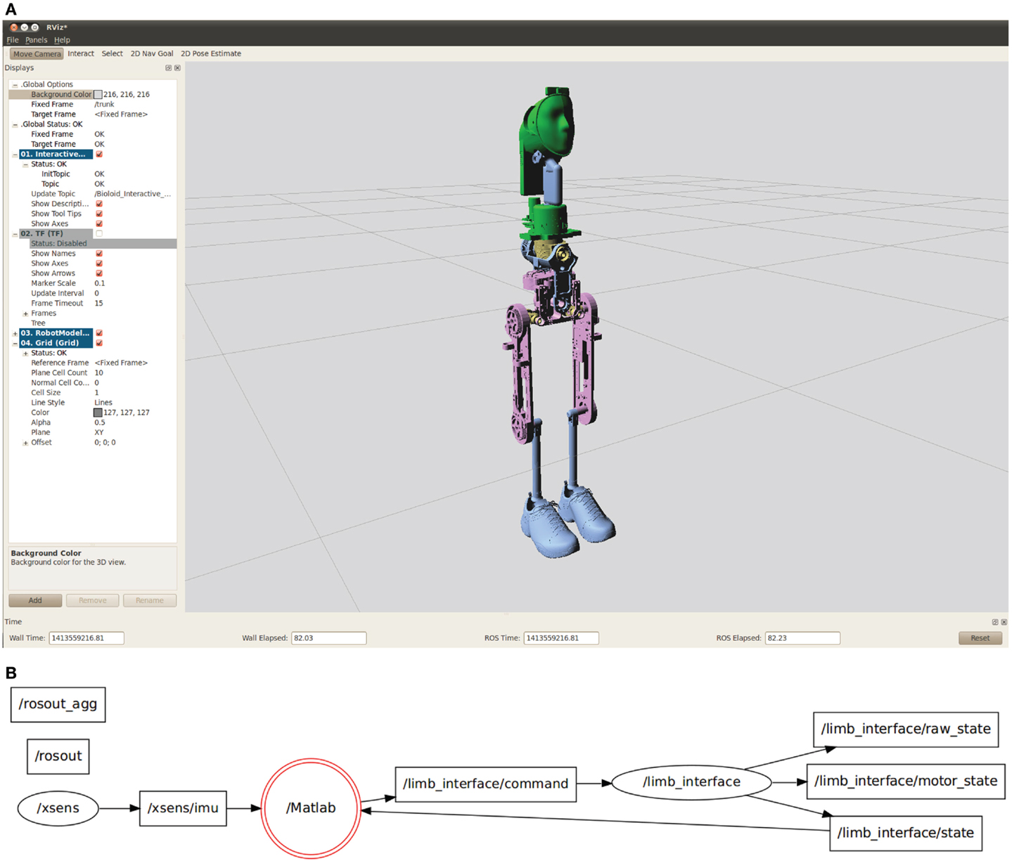
Figure 10. (A) Screenshot of Herbert in Rviz. (B) Overview of the ROS nodes captured from rxgraph.
Result
Network
Figure 11A shows a setup for testing and debugging the high-speed communication (see High-Speed Communication section). In this experiment, we sent frames from the central controller to three high-current BLDC controllers. The frames travel around the network until they are returned to the central controller. To test the integrity of the network, the central controller then checks in the processed data for not having any errors and validates the returned data. Using this setup, we can also test the latency of the complete system using a logic analyzer and the FPGA’s IO pins. On the central controller we set an IO pin high when the software sends a send command and pulls it low when the interconnect has received the complete frame on the RX line. This is used to measure the complete time a frame takes from the moment the software decides to send a frame until it has traveled around the network and ready to be processed by the software. On the modules we set an IO pin high when we receive a start of frame and low when we get an end of frame. The time it takes to send three sub-frames from the central controller around the network consisting of three FPGA modules with a payload of 150 bytes to each module and back is shown in Figure 11B. In this figure you can clearly see the three sub-frames and the very small latency between the modules.
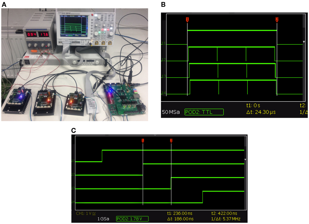
Figure 11. (A) This setup is for testing the network protocol and latency of the system with 3 high-current BLDC Controller and an early prototype of the central controller. (B). This is a screenshot from the logic analyzer of the complete frame passing through the system. The top plot is the hub, set high when it receives a sent signal and pulled low when the frame has been received and processed. The complete time for three modules each receiving 150 bytes of data takes 24.3 μs. (C) This is the latency between FPGA modules. We set an IO pin high when the FPGA received a start of frame and captured using an logic analyzer. The latency between a module is 0.186 μs.
To get a clearer idea of the latency between modules we can take a closer look at the beginning of the transmission as seen in Figure 11C. It shows a very repeatable delay of 0.186 μs between each module tδ. You can also see that the time from the sent signal to the first module receiving a frame ts is 0.27 μs. This was also constant during all the experiments. The final measurement we took was the time from the end of the frame leaving the last FPGA until the central controller had received and processed the complete frame tr. This was 0.21 μs and meant that the software could process the return frame. As the network is running at 200 Mb/s and we are 8 b/10 b encoding the transmission we can also work out the time it takes to transmit the signal tb which is 0.05 μs. From all this we created the equation 1 modeling this system to make predictions about the complete time for the system to send a frame with different numbers of modules and payload lengths.
In the equation t is the total time, ts represents the sent time, and tr is the received time. Also Mi is the module payload for each i = 1, 2, …, n module, tb is the time to transmit 1 byte, 8 b/10 b encoded, and finally, tδ is the module latency which is constant. We also tested the low amp BLDC controller timings compared to the high current BLDC controllers and verified that they both have identical network timing which is what we predicted as they share the same physical hardware and software.
Using the same evaluation method, we tested the complete communication network on Herbert with all 13 FPGA modules. For the full robot we used a payload size of 75 bytes in all frames for both controller types. This test verified our earlier finding and gave an overall time of 56 μs for the complete communication. We could also verify that the robot fully running we rarely dropped a packet.
Joint Control and Compliance
To verify that the compliant actuation design works as expected we performed four experiments. The first two experiments verified that it could track a desired trajectory and torque. The third experiment was to quantify the compliance of the joints and the last experiment was to test our sensor fault detection algorithm.
The first experiment performed a simple PD position controller test on the left knee joint. A desired position in the form of a sine wave slowly increasing in amplitude was sent to the knee controller. The desired trajectory and the recorded position can be seen in the result shown in Figure 12A. This shows that the knee joint was able to track the desired position with little error and that the knee joint could reach a velocity of 462.8°/s.
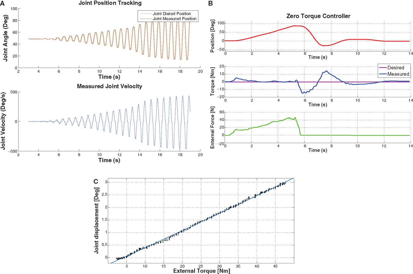
Figure 12. (A) This is a graph of Herbert’s knee joint, tracking a desired position in the air. The main point of this graph is to demonstrate the maximum speed record, which was 462.8°/s while still tracking the desired position. (B) This graph demonstrates the torque controller. With the desired torque set to 0 Nm for the hip pitch joint and then push with an external force meter. As you can see the joint is pushed to 90° and then the external force is released after 5.8 seconds. Which causes the joint to fall back to the 0° due to gravity. (C) This graph shows the displacement of the joint when an external force is applied to it. This shows that the compliant element has a linear behavior.
The second experiment was to validate the torque controller. We used again a simple PD controller and set the desired torque of the hip pitch joint to 0 Nm while pushing the leg with an external force. The results are displayed in Figure 12B. As it can be seen from the graph, an external force was applied by pushing the hip up to 90°. Then the external force was removed after five seconds causing the leg to drop due to gravity. As shown clearly, the leg swings similar to a dampened pendulum as we have not compensated for friction or gravity in the controller for this experiment. The tracking error is due to the low gains in the controller, with higher gains oscillation is introduced into the system.
The third experiment was to characterize the compliant element of Herbert. We measured an external force which was applied to the hip joint at known distance from the joint axis. We have been able to record this force and the deflexion in the joint angle with the result that the compliant joint has a very linear behavior as displayed in Figure 12C. The only downside of the compliant element is that at low forces (<4 Nm) there is no compliance. We believe this is due to friction in the system.
The fourth experiment was to test our algorithm for sensor fault detect. As we mentioned earlier, our compliant joint has two sensors to measure the joint position, while the primary sensor is an optical encoder mounted directly on the joint and the second sensor is the motor position encoder. After we have mapped the motor encoder position into the joint position we are then able to compare the position and velocity value from each sensor. By using equation 2 we are able to detect both errors in the data and sensor failure. For this experiment we set the desired position of the hip joint in the trajectory of a sin wave. We then simulated signal noise on the motor encoder, which could for example be caused by a faulty sensor. Then after one second we simulated the joint encoder not responding, this might be caused by the sensor dying or a cable becoming disconnected. Furthermore, we dropped packets and added random data to simulate corrupted data. As shown from the results in Figure 13A we were able to detect the sensor failure as well as the errors in the data. Here, the green line is the error in the data and the red line is the fault detected.
where γ is the error, q is joint position, is the joint velocity, and K is a scale factor.
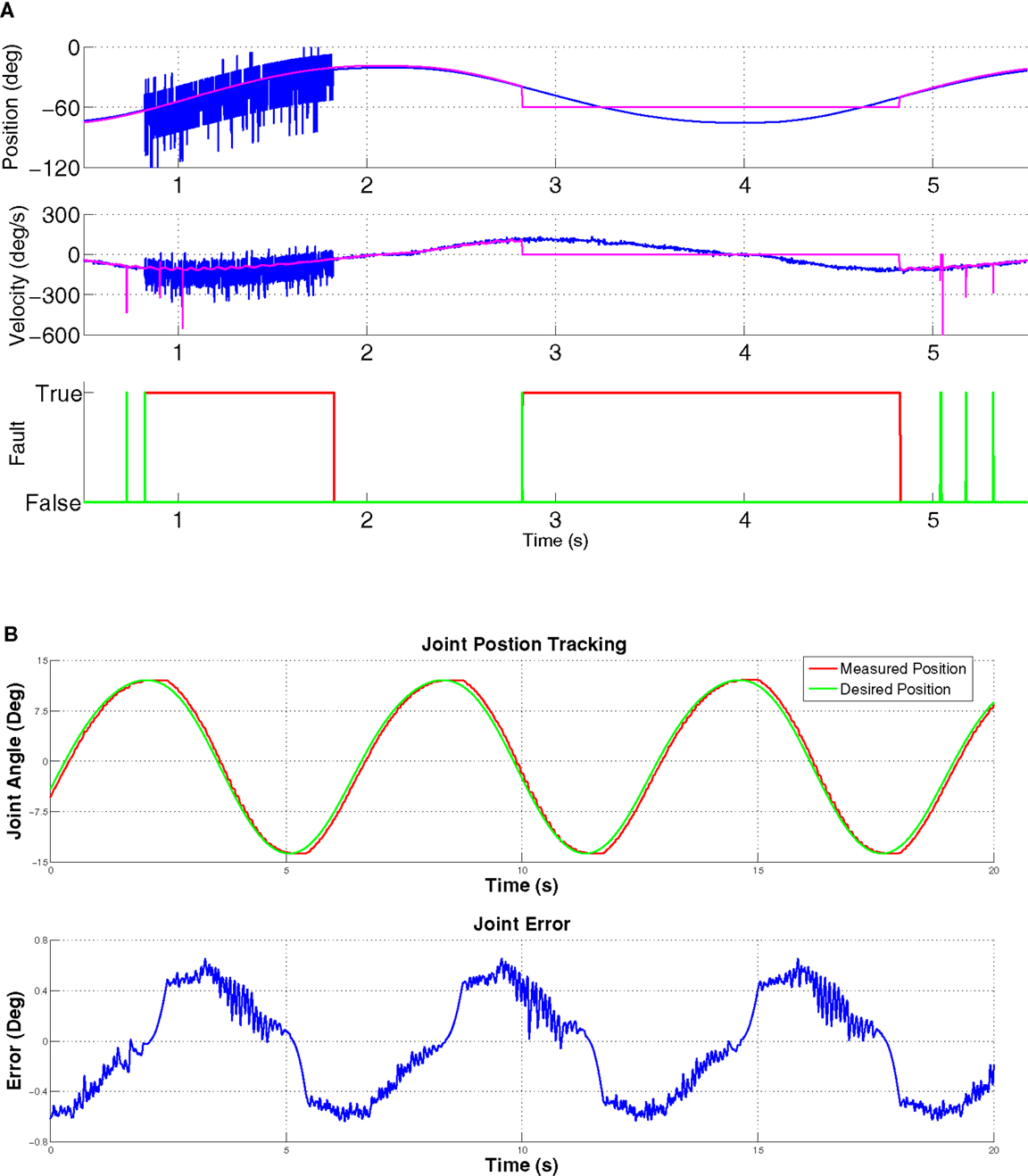
Figure 13. (A) Demonstration of error detection in the joint and motor position encoders. At 0.5 seconds there is an error in the joint encoder position, this could be from noise on the communication line or from the encoder. This is detected and shown with the first green fault detection. Then after 0.7 seconds we simulated an error on the motor encoder for 1 second which simulates a faulty sensor. This fault is detected and classed as a sensor failure as seen with the red fault detection being red. At 2.8seconds we simulated the encoder no longer responding and giving a constant value of zero. As you can see the system also detects this failure and sets the fault to true. (B) Joint trajectory of the compact joint. As you can see from this graph, the joint is able to track the desired position but due to the backlash there is an error in the tracking. The maximum error is coursed when the desired position changes direction as the joint has to overcome the backlash before the trajectory can be reversed.
To verify that the compact module was a good low-cost replacement for harmonic drives it was tested using a simple PD controller controlling the desired angular position of the waist. The result of this test can be seen in Figure 13B. As you can see the joint was able to track the desired trajectory but there was some error caused by backlash. As shown in the error graph, there is an error of ±0.7°. With the PD controller switched off we could measure 0.73° of backlash in the joint. One of the main causes of this backlash was the tolerance of the machined parts. In the future we will try machining these parts with higher tolerance which should improve this. To test the strength of the compact joint we tested it to 150 Nm, as well as testing its shock resistance by lightly hitting the joint at a distance of 40 cm with a hammer. Both of these tests did not cause a mechanical failure.
Squatting
We needed to validate the strength of the legs to ensure that they would have the strength we required for walking. To test this we made Herbert squat on the right leg as it was supported in the frontal plane so the robot only had to balance in the sagittal plane. In Figure 14A, five pictures show Herbert transforming from a standing position on one leg to a squatting position and then standing back up. We ran this squatting motion over several cycles and measured the torque in each joint as well as the joint position. A plot of this can be seen in Figure 14B. As it can be seen Herbert’s knee had a maximum torque value of 51 Nm when he started to stand up. The hip pitch joint did not have to produce much torque as it only had to balance the torso. The torque in the hip was mainly due to the CoM being shifted forward due to the left leg being forward. As the knee joint and pitch hip joint have been designed with the same motors and ball screws, we felt that we did not need to test them independently. This test produced half the maximum torque of the joint but showed that the legs have the strength to support Herbert in the single support phase of walking.
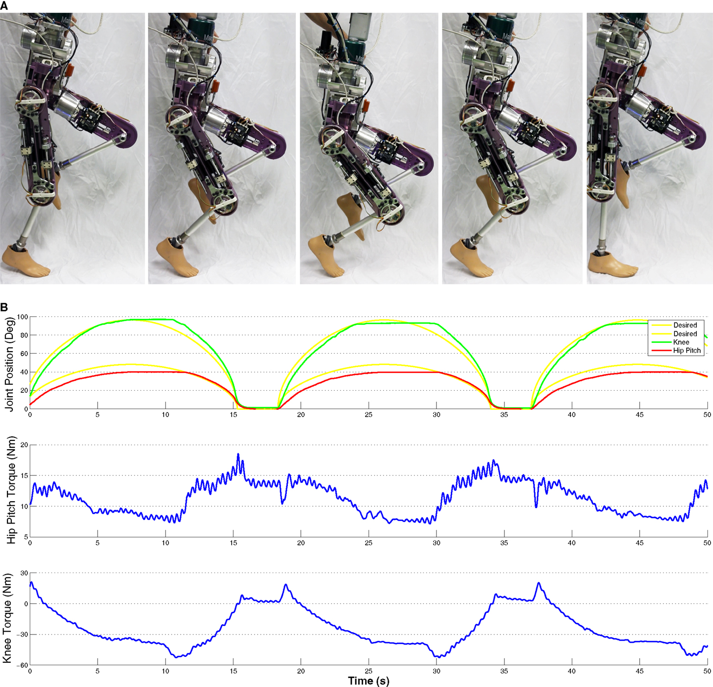
Figure 14. (A) Herbert squatting on one leg whilst being supported in the sagittal plane. This demonstrates that Herbert’s legs have the torque to support him in single-phase walking. (B) Graph of Herbert squatting, measured torque and joint position. This shows that Herbert can produce over 55 Nm of torque whilst following a desired trajectory.
Balancing
To demonstrate that all Herbert’s subsystems work together as a complete system and that all the DOFs and the IMU are working together correctly as well as ROS being successfully integrated we implemented a very simple balancer in ROS. For this experiment Herbert was standing completely free with no external support. This balancing controller was designed to keep the torso’s CoM above the hips by adjusting the desired hip pitch joint position. To calculate the torso’s CoM compared to the hip we used the IMU mounted in the chest with the assumption that the floor was flat. By using a simple PD controller we were able to stabilize Herbert when an external force was applied. By using a force meter we were able to measure the applied external force. With this controller Herbert was able to be pushed with 33.2 N for a maximum CoM displacement of 2.2° before Herbert fell down. A picture of this experiment can be seen in Figure 15A. Figure 15B shows the results of this experiment, the top plot is the hip joint position in degrees, the middle plot is the external force in N and the bottom plot is the error in the CoM of the upper body. We pushed Herbert three times in the sagittal plane from behind with the maximum force of 30.2 N. Each time Herbert would counter the force by moving its hip pitch joint. When the force was removed Herbert would return to its natural stable position. We should also point out that as Herbert was designed to have a good and symmetrical weight distribute it naturally balances itself when it is in its home position e.g., standing up straight.
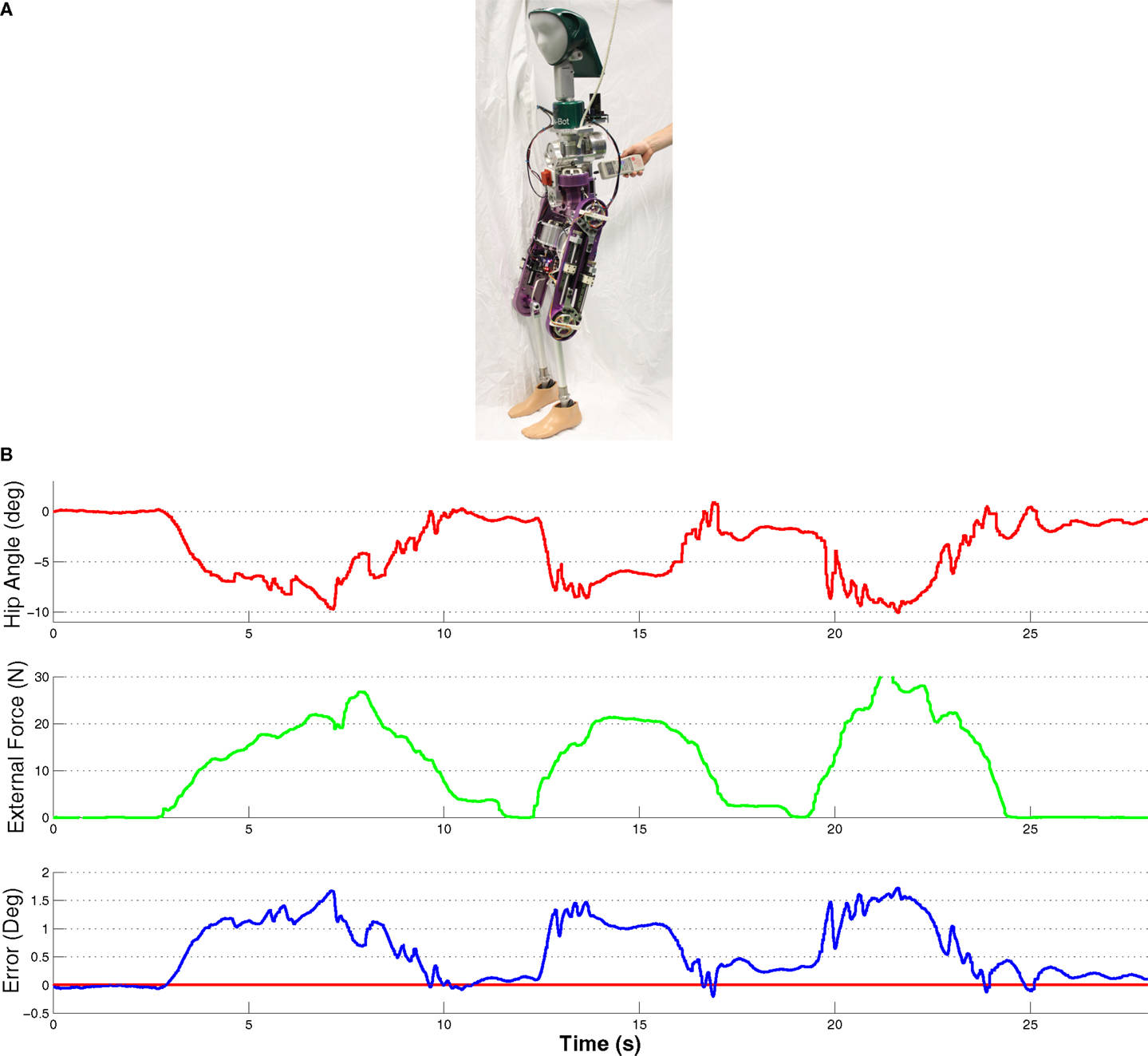
Figure 15. (A) Herbert balancing when an external force of 25.6N is applied and with no external support in any plane. (B). Graph of Herbert balancing when an external force is applied. This shows Herbert moving his hip to keep his CoM over his feet when an external force is applied to him.
Discussion
One of the primary aims for this humanoid robot was lowering the cost compared to other full-sized humanoids currently available. In Table 3 we estimated the total cost of our completed humanoid excluding hands, batteries, and external PC. This table therefore shows that we are able to produce our complete humanoid robot for around €35,000. Although, this sum excludes the cost of labor and small expendable items, for example cables and screws. A projection of how this finished humanoid will look is shown in Figure 1B. It is obvious that the main expenses are the motors as the large Robodrives used in the lower body cost €842 each. Nevertheless, it is true that the costs of the mechanical components, which include the cost of the ball screw and cycloidal reducer, are very low as a lot of effort was put into reducing the number of components used and the cost of manufacturing these components. Over a couple of iterations we were also able to combine different structural components into a single part. Although it was more complex to machine this single part, it was overall cheaper than the combined cost of a number of smaller and more simplified parts. Also 90% of the parts were manufactured in-house with low-cost CNC machines which show that our design has been optimized for simplified production.
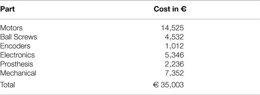
Table 3. Total cost of the humanoid Herbert.
Conclusion
In this article we presented the latest progress of the development of our anthropometrically correct humanoid robot Herbert. We have shown all the DOFs of the Herbert’s completed design, with a total weight of 35.5 kg and the breakdown of the €35,000 total cost. We have also described the hardware design we have used throughout the design of Herbert as well as the electronics we have built to control all of Herbert’s joints. We have given an overview of the software architecture that we have used to produce a flexible system so that users of different levels can run experiments on Herbert. In the Results section, we have demonstrated that Herbert joints are capable of 462.8°/s tracking a trajectory. We have also shown that the joints are also compliant and that we are able to directly control their torque. In the end we have demonstrated that Herbert is ready to start walking and balancing by showing that the leg joints are capable of squatting and that it can balance when an external force is applied. Our next step for Herbert is to start working on a more sophisticated balancer and to make him walk.
Conflict of Interest Statement
The authors declare that the research was conducted in the absence of any commercial or financial relationships that could be construed as a potential conflict of interest.
Acknowledgments
This work was supported by the DFG cluster of excellence ‘Cognition for Technical systems – CoTeSys’ of Germany.
References
Aikawa, H., Shimomura, K., Kondo, H., Morishima, A., and Takanishi, A. (2006). “Development of a new humanoid robot WABIAN-2,” in Proceedings 2006 IEEE International Conference on Robotics and Automation, 2006. ICRA 2006 (Orlando: IEEE), 76–81. doi: 10.1109/ROBOT.2006.1641164
Alfayad, S., Ouezdou, F. B., and Namoun, F. (2011). New 3-dofs hybrid mechanism for ankle and wrist of humanoid robot: modeling, simulation, and experiments. J. Mech. Des. 133, 021005. doi:10.1115/1.4003250
Allgeuer, P., Schwarz, M., Pastrana, J., Schueller, S., Missura, M., and Behnke, S. (2013). “A ROS-based software framework for the NimbRo-OP humanoid open platform,” in Proceedings of 8th Workshop on Humanoid Soccer Robots, IEEE Int. Conf. on Humanoid Robots, Atlanta.
Ando, N., Suehiro, T., Kitagaki, K., Kotoku, T., and Yoon, W.-K. (2005). “RT-middleware: distributed component middleware for RT (robot technology),” in Intelligent Robots and Systems, 2005.(IROS 2005). 2005 IEEE/RSJ International Conference on (Alberta: IEEE), 3933–3938.
Armstrong, H. G., et al. (1988). “Anthropometry and mass distribution for human analogues. Volume 1. Military male aviators,” in Aerospace Medical Research Lab Wright-Patterson AFB Ohio USA, Tech. Rep.
Asfour, T., Schill, J., Peters, H., Klas, C., Bücker, J., Sander, C., et al. (2013). “ARMAR-4: A 63 DOF torque controlled humanoid robot,” in IEEE/RAS International Conference on Humanoid Robots (Humanoids), Atlanta.
Asfour, T., Welke, K., Azad, P., Ude, A., and Dillmann, R. (2008). “The Karlsruhe Humanoid Head,” in Humanoid Robots, 2008. Humanoids 2008. 8th IEEE-RAS International Conference on (Daejung: IEEE), 447–453. doi:10.1109/ICHR.2008.4755993
Baglini, E., Cannata, G., and Mastrogiovanni, F. (2010). “Design of an embedded networking infrastructure for whole-body tactile sensing in humanoid Robots,” in 2010 10th IEEE-RAS International Conference on Humanoid Robots (Nashville: IEEE), 671–676. doi:10.1109/ICHR.2010.5686834
Beira, R., Lopes, M., Praga, M., Santos-Victor, J., Bernardino, A., Metta, G., et al. (2006). “Design of the robot-cub (iCub) head,” in Robotics and Automation, 2006. ICRA 2006. Proceedings 2006 IEEE International Conference on (Orlando: IEEE), 94–100. doi:10.1109/ROBOT.2006.1641167
Bradski, G., and Kaehler, A. (2008). Learning OpenCV: Computer Vision with the OpenCV Library. O’Reilly Media, Inc.
Breazeal, C., and Scassellati, B. (1999). “How to build robots that make friends and influence people,” in Intelligent Robots and Systems, 1999. IROS’99. Proceedings. 1999 IEEE/RSJ International Conference on, Vol. 2 (IEEE), 858–863.
Bruyninckx, H. (2001). “Open robot control software: the OROCOS project,” in Robotics and Automation, 2001. Proceedings 2001 ICRA. IEEE International Conference on, Vol. 3 (Seoul: IEEE), 2523–2528.
Cheng, G., Hyon, S., Morimoto, J., Ude, A., Hale, J. G., Colvin, G., et al. (2007). CB: a humanoid research platform for exploring neuroscience. Adv. Robot. 21, 1097–1114. doi:10.1163/156855307781389356
Collett, T. H., MacDonald, B. A., and Gerkey, B. P. (2005). “Player 2.0: toward a practical robot programming framework,” in Proceedings of the Australasian Conference on Robotics and Automation (ACRA 2005) (Sydney: ARAA), 145.
Delaunay, F., de Greeff, J., and Belpaeme, T. (2009). “Towards retro-projected robot faces: an alternative to mechatronic and android faces,” in Robot and Human Interactive Communication (RO-MAN2009) (Toyama: IEEE), 306–311.
Delaunay, F., de Greeff, J., and Belpaeme, T. (2011). “Lighthead robotic face,” in Proceedings of the 6th International Conference on Human-robot interaction (HRI’11) (Lausanne: IEEE), 101.
Diftler, M. A., Mehling, J. S., Abdallah, M. E., Radford, N. A., Bridgwater, L. B., Sanders, A. M., et al. (2011). “Robonaut 2-the first humanoid robot in space,” in Robotics and Automation (ICRA), 2011 IEEE International Conference on (Shanghai: IEEE), 2178–2183.
Enoch, A., Sutas, A., Nakaoka, S., and Vijayakumar, S. (2012a). “Blue: a bipedal robot with variable stiffness and damping,” in Humanoid Robots (Humanoids), 2012 12th IEEE-RAS International Conference on (Osaka: IEEE), 487–494.
Enoch, A., Sutas, A., Nakaoka, S., and Vijayakumar, S. (2012b). “Blue: a bipedal robot with variable stiffness and damping,” in IEEE-RAS International Conference on Humanoid Robots (Osaka: IEEE), 487–494.
Gouaillier, D., Hugel, V., Blazevic, P., Kilner, C., Lafourcade, P., Marnier, B., et al. (2009). “Mechatronic design of NAO humanoid,” in Conference on Robotics and Automation (Kobe: IEEE), 769–774.
Grizzle, J. W., Hurst, J., Morris, B., Park, H.-W., and Sreenath, K. (2009). “MABEL, a new robotic bipedal walker and runner,” in American Control Conference, 2009. ACC’09 (Missouri: IEEE), 2030–2036.
Haddadin, S., Parusel, S., Belder, R., and Albu-Schäffer, A. (2013). “It is (almost) all about human safety: a novel paradigm for robot design, control, and planning,” in Computer Safety, Reliability, and Security (Springer), 202–215.
Hashimoto, M., and Morooka, D. (2006). Robotic facial expression using a curved surface display. J. Robot. Mechatron. 18, 504–510.
Hirai, K., Hirose, M., Haikawa, Y., and Takenaka, T. (1998). “The development of Honda humanoid robot,” in Proceedings of the 1998 IEEE International Conference on Robotics and Automation (Leuven: IEEE), 1321–1326.
Hobbelen, D., de Boer, T., and Wisse, M. (2008). “System overview of bipedal robots flame and tulip: tailor-made for limit cycle walking,” in Intelligent Robots and Systems, 2008. IROS 2008. IEEE/RSJ International Conference on, ed. M. Hackel (Nice: IEEE), 2486–2491. doi:10.1109/IROS.2008.4650728
Hurst, J. W. (2011). The electric cable differential leg: a novel design approach for walking and running. Int. J. HR 8, 301–321. doi:10.1142/S0219843611002459
Kanehiro, F., Hirukawa, H., and Kajita, S. (2004). Openhrp: open architecture humanoid robotics platform. Int. J. Robot. Res. 23, 155–165. doi:10.1177/0278364904041324
Kanehiro, F., Ishiwata, Y., Saito, H., Akachi, K., Miyamori, G., Isozumi, T., et al. (2006). “Distributed control system of humanoid robots based on real-time ethernet,” in 2006 IEEE/RSJ International Conference on Intelligent Robots and Systems, IEEE. 2471–2477. doi:10.1109/IROS.2006.281691
Kaneko, K., Harada, K., Kanehiro, F., Miyamori, G., and Akachi, K. (2008). “Humanoid robot HRP-3,” in 2008 IEEE/RSJ International Conference on Intelligent Robots and Systems (Nice: IEEE), 2471–2478. doi:10.1109/IROS.2008.4650604
Kaneko, K., Kanehiro, F., Morisawa, M., Miura, K., Nakaoka, S., and Kajita, S. (2009). “Cybernetic human HRP-4C,” in Humanoid Robots, 2009. Humanoids 2009. 9th IEEE-RAS International Conference on (Paris: IEEE), 7–14.
Kuratate, T., Pierce, B., and Cheng, G. (2011). ““Mask-Bot” – A Life-Size Talking Head Animated Robot for AV Speech and Human-Robot Communication Research,” in Proceedings of the International Conference on Auditory-Visual Speech Processing (AVSP 2011), Volterra.
Lee, D.-W., Lee, T.-G., So, B., Choi, M., Shin, E.-C., Yang, K., et al. (2008). “Development of an android for emotional expression and human interaction,” in Seventeenth world congress the international federation of automatic control (Seoul: IFAC), 4336–4337.
Lohmeier, S., Buschmann, T., and Ulbrich, H. (2009). System design and control of anthropomorphic walking robot LOLA. IEEE ASME Trans. Mechatron. 14, 658–666. doi:10.1109/TMECH.2009.2032079
Metta, G., Fitzpatrick, P., and Natale, L. (2006). Yarp: yet another robot platform. Int. J. Adv. Robot. Syst. 3, 43–48. doi:10.5772/5761
Nagakubo, A., Kuniyoshi, Y., and Cheng, G. (2003). Development of a high-performance upper-body humanoid system. Adv. Robot. 17, 149–164. doi:10.1163/156855303321165105
Nelson, G., Saunders, A., Neville, N., Swilling, B., Bondaryk, J., Billings, D., et al. (2012). Petman: a humanoid robot for testing chemical protective clothing. J. Robot. Soc. Jpn. 30, 372–377. doi:10.7210/jrsj.30.372
Oh, J.-H., Hanson, D., Kim, W.-S., Han, Y., Kim, J.-Y., and Park, I.-W. (2006). “Design of android type humanoid robot albert HUBO,” in 2006 IEEE/RSJ International Conference on Intelligent Robots and Systems (Beijing: IEEE), 1428–1433. doi:10.1109/IROS.2006.281935
Ott, C., Baumg, C., Mayr, J., Fuchs, M., Burger, R., Lee, D., et al. (2010). “Development of a biped robot with torque controlled joints,” in International Conference on Humanoid Robots (Nashville: IEEE), 167–173.
Park, I.-W., Kim, J.-Y., Lee, J., and Oh, J.-H. (2005). “Mechanical design of humanoid robot platform KHR-3 (KAIST humanoid robot 3: HUBO),” in Humanoid Robots, 2005 5th IEEE-RAS International Conference on (Tsukuba: IEEE), 321–326.
Parmiggiani, A., Metta, G., and Tsagarakis, N. (2012). “The mechatronic design of the new legs of the iCub robot,” in IEEE-RAS International Conference on Humanoid Robots (Osaka: IEEE), 481–486.
Pierce, B., and Cheng, G. (2014). “Versatile modular electronics for rapid design and development of humanoid robotic subsystems,” in Advanced Intelligent Mechatronics (AIM), 2014 IEEE/ASME International Conference on (Besancon: IEEE), 735–741.
Pierce, B., Takaaki, K., Christian, V., and Cheng, G. (2012). ““Mask-bot 2i”: an active customisable robotic head with interchangeable face,” in Proceedings of IEEE-RAS International Conference on Humanoid Robots (Humanoids 2012) (Osaka: IEEE), 520–525.
Pratt, G. A., and Williamson, M. M. (1995). “Series elastic actuators,” in Intelligent Robots and Systems 95.’Human Robot Interaction and Cooperative Robots’, Proceedings. 1995 IEEE/RSJ International Conference on, Vol. 1 (Pittsburgh: IEEE), 399–406.
Pratt, J., Chew, C.-M., Torres, A., Dilworth, P., and Pratt, G. (2001). Virtual model control: an intuitive approach for bipedal locomotion. Int. J. Robot. Res. 20, 129–143. doi:10.1177/02783640122067309
Quigley, M., Conley, K., Gerkey, B., Faust, J., Foote, T., Leibs, J., et al. (2009). “Ros: an open-source robot operating system,” in ICRA Workshop on Open Source Software, Vol. 3, 5.
Tellez, R., Ferro, F., Garcia, S., Gomez, E., Jorge, E., Mora, D., et al. (2008). “Reem-B: an autonomous lightweight human-size humanoid robot,” in Humanoid Robots, 2008. Humanoids 2008. 8th IEEE-RAS International Conference on (Daejeon: IEEE), 462–468.
Tilley, A. R. (2002). The Measure of Man and Woman: Human Factors in Design. John Wiley and Sons, Inc.
Tsagarakis, N. G., Saglia, J., and Caldwell, D. G. (2011). “The design of the lower body of the compliant humanoid robot “cCub”,” in 2011 IEEE International Conference on Robotics and Automation (IEEE), 2035–2040. doi:10.1109/ICRA.2011.5980130
Vanderborght, B., Tsagarakis, N. G., Semini, C., Van Ham, R., and Caldwell, D. G. (2009). “Maccepa 2.0: adjustable compliant actuator with stiffening characteristic for energy efficient hopping,” in Robotics and Automation, 2009. ICRA’09. IEEE International Conference on (Kobe: IEEE), 544–549.
Veneman, J. F., Ekkelenkamp, R., Kruidhof, R., van der Helm, F. C., and van der Kooij, H. (2006). A series elastic-and bowden-cable-based actuation system for use as torque actuator in exoskeleton-type robots. Int. J. Robot. Res. 25, 261–281. doi:10.1177/0278364906063829
Keywords: humanoid robot, compliant control, anthropometrically correct humanoid robot, human performance, torque controllable
Citation: Pierce B and Cheng G (2015) Herbert: design and realization of a full-sized anthropometrically correct humanoid robot. Front. Robot. AI 2:14. doi: 10.3389/frobt.2015.00014
Received: 16 December 2014; Accepted: 19 May 2015;
Published: 25 June 2015
Edited by:
Lorenzo Natale, Istituto Italiano di Tecnologia, ItalyReviewed by:
Giovanni Stellin, Telerobot Labs Srl, ItalyKensuke Harada, National Institute of Advanced Industrial Science and Technology, Japan
Copyright: © 2015 Pierce and Cheng. This is an open-access article distributed under the terms of the Creative Commons Attribution License (CC BY). The use, distribution or reproduction in other forums is permitted, provided the original author(s) or licensor are credited and that the original publication in this journal is cited, in accordance with accepted academic practice. No use, distribution or reproduction is permitted which does not comply with these terms.
*Correspondence: Brennand Pierce, Institute for Cognitive Systems, Technische Universität München, Karlstrasse 45/II, Munich 80333, Germany, bren@tum.de