Robot Control for Task Performance and Enhanced Safety under Impact
 Yiannis Karayiannidis
 Leonidas Droukas
 Dimitrios Papageorgiou
 Zoe Doulgeri
- 1Department of Signals and Systems, Chalmers University of Technology, Gothenburg, Sweden
- 2Center for Autonomous Systems, Royal Institute of Technology (KTH), Stockholm, Sweden
- 3Department of Electrical and Computer Engineering, Aristotle University of Thessaloniki, Thessaloniki, Greece
A control law combining motion performance quality and low stiffness reaction to unintended contacts is proposed in this work. It achieves prescribed performance evolution of the position error under disturbances up to a level related to model uncertainties and responds compliantly and with low stiffness to significant disturbances arising from impact forces. The controller employs a velocity reference signal in a model-based control law utilizing a non-linear time-dependent term, which embeds prescribed performance specifications and vanishes in case of significant disturbances. Simulation results with a three degrees of freedom (DOF) robot illustrate the motion performance and self-regulation of the output stiffness achieved by this controller under an external force, and highlights its advantages with respect to constant and switched impedance schemes. Experiments with a KUKA LWR4+ demonstrate its performance under impact with a human while following a desired trajectory.
1. Introduction
A key challenge for the successful introduction of robots in human centered environments, as domestic assistants or co-workers, is the concurrent resolution of the issues of task performance and safety for the coexisting human (De Santis et al., 2010). Despite the need for the existence of collision avoidance mechanisms, to date, and in the context of service robots, there exists no sensor system that can guarantee collision avoidance with sufficient reliability. Hence, the possibility of collision with a human should still be accounted by minimizing the harm of such collisions.
Humans cope superbly with collisions and contact uncertainty by flexibly modulating their arm/hand compliance. Compliance protects the human from excessive forces during impact and can be achieved in robots either passively by using flexible components in the robot’s structure or actively by the controller. Passive compliance is very important for the reduction of the initial collision force, which is responsible for the so-called pre-collision safety (Heinzmann and Zelinsky, 2003), and may be achieved by using deformable material to cover the robot or by building robots with compliant joints (Choi et al., 2008; Wolf and Hirzinger, 2008; Tsagarakis et al., 2011; Albu-Schaeffer et al., 2012). Variable stiffness actuation allows the regulation of the joint stiffness to values set by a higher level controller. When joint mechanical compliance is absent, then all the responsibility of keeping collisions harmless is being transferred to the controller. Active compliance or joint stiffness regulation enhances comfort and gives the impression that the human is in control in intentional contacts but at unintentional contacts, it may fail to reduce the initial collision force due to the delays introduced in the control system by the contact detection and reaction mechanisms. The delay introduced by the proposed detection methods vary depending on sensing and/or the general method’s computational requirements (Golz et al., 2015). The residual torque method is a robot model-based contact detection utilizing proprioceptive sensors and one or more external RGB-D sensors to localize the contact point (De Luca and Mattone, 2005; De Luca et al., 2006; Magrini et al., 2015). Alternatively, variations in control effort can be utilized for estimating human contact without force sensing (Erden and Tomiyama, 2010). Recently, the utilization of a disturbance observer is proposed in a frequency-shaped impedance control scheme, which, however, is mainly addressed to intentional physical human–robot interaction (Oh et al., 2014). The problem of discriminating contacts to intentional and unintentional is also examined in Golz et al. (2015) where a machine learning method combined with features of physical contact models is proposed. Once a collision is detected, the robot switches from the control law associated to its nominal task to that of a reaction control law. Switching may be another source of delay and may in general adversely affect the stability of the overall switched system (Haddadin et al., 2008). Moreover, in the case of variable stiffness actuators, the bandwidth of the stiffness actuating system is crucial for responding promptly to unexpected impacts. On the other hand, controllers achieving an output impedance at safety level are characterized by poor performance. Traditionally, performing robot tasks with performance quality is associated with stiffness and hence a potentially unsafe contact (Bicchi and Tonietti, 2004). Thus, non-linear stiffness terms are introduced in impedance controllers for physical human–robot interaction control purposes setting different stiffness values in relation to deviation sizes around a nominal trajectory (Lee and Ott, 2011).
As service robots have to perform useful tasks for humans in a dynamic and uncertain environment, quality of performance is desired. The prescribed performance control methodology introduced in Bechlioulis and Rovithakis (2008) has been utilized for designing robot motion and/or force controllers guaranteeing prescribed performance for the output error (Bechlioulis et al., 2012; Karayiannidis and Doulgeri, 2012). In fact, prescribed performance controllers do not allow the output error to escape the performance region guaranteeing prescribed performance; they are robust to any external disturbance by utilizing a transformed error, which is approaching infinity at the performance boundaries and is not defined outside the performance region. Consequently, the control effort generated by a prescribed performance controller is increasing as the error approaches the boundary under the effect of a disturbance. The considerable stiffness induced by the prescribed performance control action may be undesired or even dangerous, if humans share the robot’s workspace. Moreover, in practice, the output error may be forced outside the performance region due to the inability of the physical actuator to provide the demanded control effort or by not employing sufficiently high sampling rates. In such instances the system becomes uncontrollable.
The aim of this work is to concurrently address the competing requirements of motion performance and compliance under impact by designing a control scheme that achieves prescribed performance in nominal operation (high stiffness), a compliant reaction at impact (low stiffness) and smooth transition between the two modes. The system self-regulates the output stiffness according to the disturbance level without explicit collision detection and control switching which are subjective to delays and jeopardize performance and stability. The feedback controller is model-based assuming knowledge of the robot’s model and measurements of joint positions and velocities. The paper is organized as follows: In Section 2, we consider a simple first-order integrator system in order to define the nominal performance operation and impact reaction modes and introduce the basic control idea. Section 3 proposes a passivity-based motion controller utilizing the robot model, with an outer loop based on the control idea introduced in Section 2 achieving prescribed performance of a robot’s task position tracking error and low stiffness compliance under impact. Section 4 presents simulation and experimental results illustrating the motion performance and self output stiffness regulation of the proposed controller under impact while conclusions are drawn in Section 5.
2. Operation Modes and Control Preliminaries
Consider a first-order integrator scalar system of a tracking error e under disturbance d(t):
where u is the control input; such type of system may model a kinematically or velocity controlled, robotic degree of freedom. We shall utilize this system to define operation modes and introduce the basic control idea.
2.1. Operation Modes
For system [equation (1)], we define two modes of system operation: the nominal performance operation and impact reaction. The definition of the nominal performance system operation is motivated by the prescribed performance concept (Bechlioulis and Rovithakis, 2008). A system is under its nominal performance operation if the tracking error e(t) evolves strictly within a predefined region that is bounded by a decaying function of time constructed by the designer. Otherwise, the system is operating in the impact reaction mode. The following is the mathematical expression of the nominal performance operation:
where ρ(t) is a bounded, smooth, strictly positive, and decreasing function satisfying limt→∞ ρ(t) = ρ∞ > 0 called performance function. A candidate performance function is the exponential
with ρ0, ρ∞, l strictly positive constants expressing nominal performance specifications. Constant ρ0 = ρ(0) > |e(0)| and is selected as described in Remark 2. Constant ρ∞ represents the maximum allowable size of the output error e(t) at steady state. Furthermore, constant l, which is related to the decreasing rate of ρ(t), introduces a lower bound on the required speed of convergence of e(t). An illustration of the nominal performance error evolution and of the error evolution in the impact reaction mode is shown in Figure 1.
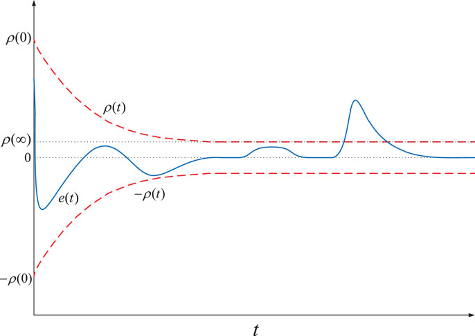
Figure 1. Nominal performance and collision reaction mode.
By considering the modulated error , we can define the system in its nominal performance operation if |ξ(t)| < 1, and in impact reaction mode if |ξ(t)| ≥ 1, i.e., when the output error evolves outside the performance bounds (Figure 1). Let us denote with D the region of nominal performance operation, i.e., D ≜ (−1,1) while Dc = ℛ \ D is the complement set of D.
2.2. Basic Control Idea
In this work, we combine both requirements of nominal performance and enhanced safety operation under impact by proposing a new controller design based on a transformation, which defines the following smooth, non-decreasing, non-linear, surjective mapping of the modulated error domain:
further satisfying the following properties:
Hence, the transformation is strictly increasing in ξ for ξ ∈ D and saturated on and beyond the prescribed performance boundaries, i.e., for ξ ∈ Dc. Moreover, the transformation is concave in the first quadrant and convex in the third. The following is a candidate transformation function illustrated in Figure 2:
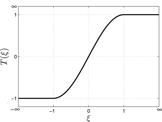
Figure 2. A sinus based transformation function.
Notice that in place of equation (6), standard polynomials satisfying equation (4), and (5) may be utilized.
The artificial potential induced by such saturated transformation:
is continuously differentiable, positive definite, i.e., 𝒱(ξ) > 0 for ξ ∈ ℛ – {0}, but it is not radially unbounded since regions 𝒱 (ξ) ≤ β are only closed for values of β < 1. Such potentials may allow a solution to escape the nominal performance region as opposed to the potentials induced by the transformations utilized in the prescribed performance controllers (Karayiannidis and Doulgeri, 2012). Figure 3 gives an illustration of the potential function induced by equation (6):
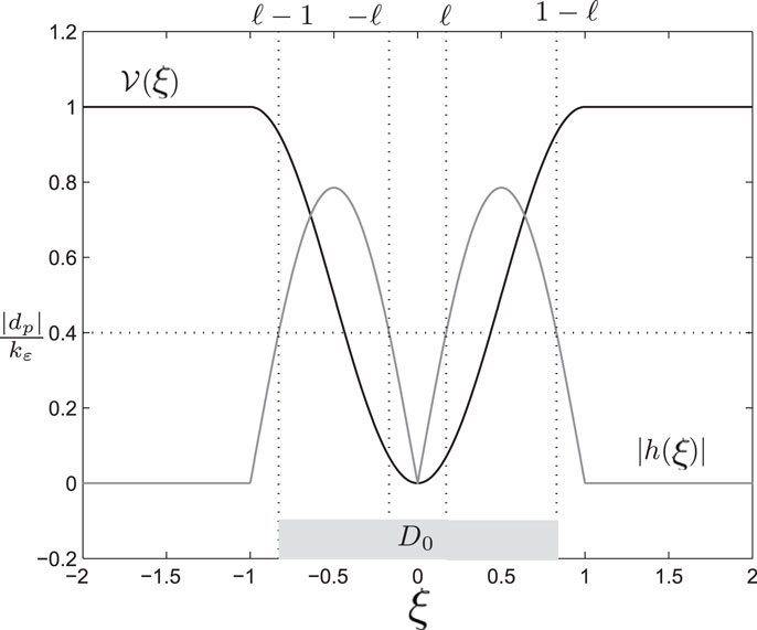
Figure 3. The potential function 𝒱(ξ) [equation (8)], the invariant set [equation (23)] and the control term |h(ξ)| [equation (13)].
Let us further define:
Notice that h(ξ) satisfies the following properties:
Property [equation (10)] is enabled by the bounded potential 𝒱 (ξ), which is not typical in control design. This type of potential is unsuitable for global asymptotic stabilization and robustness analysis but allows different control actions without switching. For the transformation function given by equation (6):
Function h(ξ) lies in the first and third quadrant satisfying equation (11); its absolute value is illustrated in Figure 3 yielding .
Using h(ξ) [equation (9)], we can design a simple control input u for equation (1) as follows:
where ks, k are positive control constants, and is non-negative and bounded; for the exponential performance function, α(t) is, further, strictly decreasing with 0 < α(t) ≤ α(0) < l, limt→∞α(t) = 0.
Remark 1. (control philosophy): In case, the error is forced outside the nominal performance region [equation (2)] by a significant disturbance owing to a collision, the control term involving h(ξ) vanishes due to property [equation (10)], while the remaining terms can be viewed as a proportional control action with a small decreasing gain in the case of the exponential performance. Hence, the proposed control law works independently of a detection or observation of the interaction force and has the advantage of avoiding switching between two controllers as opposed to other strategies.
Substituting control input [equation (14)] to the system [equation (1)] yields:
Differentiating with respect to time yields and substituting from equation (15), we get the closed-loop system expressed with respect to the modulated error:
For the unforced non-autonomous system [equation (16)], i.e., d(t) = 0, it is easy to establish that the origin ξ = 0 is a uniformly asymptotically stable equilibrium in D ⊕ Dc. Notice that if the system operates in impact reaction mode then the unforced closed-loop system [equation (16)] becomes = –ksξ; hence ξ is drawn to ±1 with a time constant 1/ks that is, the error e is reaching the boundary of the prescribed performance region ±ρ(t). Given that no disturbance is acting at the system, ξ will return to the nominal operation mode (|ξ | < 1); hence, e will cross the boundary converging uniformly and asymptotically to e = 0 (ξ = 0).
In the presence of a bounded input d(t), the following theorem establishes the range of disturbances guaranteeing system operation in nominal mode:
Theorem 1. Consider a bounded disturbance input |d(t)| < Δ for the non-linear system [equation (16)] such that:
Then, there exists an invariant set D0 ⊂ D for the system state ξ; that is, initializing within D0 guarantees a nominal performance error evolution in the sense of equation (2).
Proof: Using equation (7) for equation (16) the following can be satisfied in D: α1(|ξ|) ≤ 𝒱(ξ) ≤ α2(|ξ|) where α1, α2 are class 𝒦 functions, and
If holds, then the quantity inside the brackets in equation (19) i.e., is negative. Thus, we may write:
Next, we simplify the analysis by considering odd h(ξ) functions although the analysis can be easily extended for the case of non-symmetric functions. If h(ξ) is odd then, |h(ξ)| = h(|ξ|) and it is now easier to calculate the domain of ξ wherein . The equation can be solved with respect to |ξ| if Δ ≠ 0 and equation (17) holds; the solution ζ1, ζ2 satisfy 0 < ζ1 < ζ2 < 1 as shown in Figure 3. We can then write
Hence, defining
if ξ(0) ∈ D0 then ξ(t) ∈ D0 ⊂ D, ∀t ∈ R+, which implies that D0 is invariant and the system remains in nominal performance operation.
For the specific case of the candidate transformation function [equation (6)], the invariant set D0 illustrated in Figure 3 exists if and is given by:
with
deriving from solving equation with respect to |ξ|, while taking into consideration [equation (13)] for ξ ∈ D.
Remark 2. The maximum disturbance allowing a nominal performance operation mode [equation (17)] can be regulated by the control design constant k. Moreover, for nominal performance operation, constant ρ0 of the performance function should be selected such that equation (22) is satisfied at t = 0, i.e., .
Remark 3. When the system operates in impact reaction mode, the closed-loop system or is ISS (input-to-state stable) for the disturbance input d(t) since α(t) + ks ≥ ks > 0. If te is the time instant the disturbance vanishes, the system will return to the nominal operation in s.
Since our objective is a robot-control design, which complies with large disturbances, there is no need of choosing high values for ks in order to shrink the ultimate bound of the system given by (since limt→∞ α(t) = 0).
3. The Proposed Robot Controller
Consider a nq DOF robotic manipulator with denoting its joint position vector and pe ∈ ℛ3, Re ∈ SO(3) describing the position and the orientation of the end-effector with respect to the inertial frame, respectively. Let denotes the end-effector generalized velocity with ωe being the rotational velocity of the end-effector expressed at the inertial frame. Then, joint velocities are related to the generalized velocity with the robot Jacobian as follows:
The robot dynamic model can be written as follows:
where is the positive definite robot inertia matrix, is the vector of Coriolis and centripetal forces, is the gravity vector, is the control input joint torques and is a bounded joint disturbance typically arising by unforeseen collisions of the arm with a human or the environment. Let pd(t) ∈ ℛ3, Rd(t) ∈ SO(3) denotes the smooth and bounded desired end-effector position and orientation trajectories. Operational space tracking control employs both the position and orientation error. The position error is given by e = pe(t) – pd(t) and for the orientation error, the outer product formulation, the Euler angle representation or quaternions may be used (Siciliano et al., 2010).
For simplicity and without loss of generality, we proceed by considering the position tracking problem. Thus, our objective is to design a state feedback control law, in order to force the robot’s end-effector position pe(t) to track a given desired trajectory pd(t) with prescribed performance under its nominal operation mode in the sense of confining the evolution of each position error coordinate ei(t) within a predefined region that is bounded by ±ρi(t) under small disturbances and to enable a smooth compliant reaction outside the performance region when the impact force is greater than an allowed level, returning to the nominal mode after the disturbance vanishes. We shall call this problem Prescribed Motion Performance and Compliant Reaction(PMPCR).
Theorem 2. Consider the model of a robotic manipulator equations (25) and (26), the desired trajectory pd(t) ∈ ℛ3 and performance functions ρi(t), i = 1, 2, 3 as defined in equation (3) that incorporate the desired performance bounds of the task position tracking error elements ei = pei(t) – pdi(t) in the nominal operation mode as well as transformations Ti(ξi) as in equation (6) for the modulated error elements . Moreover, define the intermediate control signals:
where ki, ksi are positive control constants, hi(ξi) is defined as in equation (9) and . Assuming a robot motion away from singular positions, the passivity model-based control law:
with Kv being a diagonal matrix of positive control constants, where , J+(q) with being a generalized pseudo-inverse of the Jacobian (J+(q) = J−1(q) for the non-redundant case,) and vr ∈ ℛ3 having vri entries given in equation (27), solves the PMPCR problem.
Proof: Substituting equation (28) in equation (26), we obtain the closed-loop system (Slotine and Li, 1991):
Consider now the positive definite radially unbounded function:
which satisfies the following inequality
where λm, λM are positive constants related to the robot’s minimum and maximum eigenvalue of M(q) ∀q. Differentiating equation (30) with respect to time and substituting from equation (29), while taking into account the skew symmetry of , we obtain:
Let kv be the minimum entry of Kv; then, can be upper bounded as follows:
Defining the region , it is clear that:
which proves the uniform ultimately boundedness of sq. In fact, using equations (31) and (35), it can be shown that
which can be combined in the following:
demonstrating an input-to-state stability (Marquez, 2003), for the pair τd(t), sq of equation (29).
Given equation (38), sq is bounded for a bounded disturbance τd(t) and there exists a function of time dp(t) satisfying equation (38) such that sq = dp(t) and substituting yields:
Multiplying with the robot Jacobian J(q) and substituting equation (27) we obtain:
where A(t), Ks, K are diagonal matrices with entries αi(t) and ksi, ki > 0, respectively, and H(ξ) is a vector with elements hi(ξi). Each element of equation (40) is related to the error scalar system [equation (15)] having as disturbance input the ith element of J(q)dp(t) in place of the d(t) of equation (15). Let us take the example of an impact force Fext applied to the robot’s end-effector, which is mapped to the joint space as a disturbance torque τd(t) = JTFext. Let the system [equation (29)] be operating at the steady state, i.e., . From equation (38), we observe that ||dp(t)|| ~ ||τd||/kv remains the main source of disturbance at the velocity control level. As Theorem 1 implies, the controller guarantees that the system is in nominal performance operation mode when the disturbance force is less than a tunable threshold (reflecting modeling errors) but allows the system to escape this mode for higher disturbances as are those arising from collision impacts. In this case, the robot reaction is stable and compliant, returning to the nominal operation mode after the disturbance vanishes thus solving the PMPSC problem.
Remark 4. Notice that when the system operates in the impact reaction mode where hi(ξi) = 0 and αi(t) ≃ 0 (in the steady state region of the performance function), the reference velocity [equation (27)] becomes and the model-based controller [equation (28)] guarantees system stability.
Remark 5. A brief unexpected contact is so far assumed in the presentation of the proposed control law. However, if the contact persists contact forces will keep increasing even with low output stiffness since the reference position advances. In that case, a post-impact strategy that abandons the desired trajectory is mandatory so that tracking errors cease to build up.
4. Results and Discussion
4.1. Simulation Results
We consider a three DOF rotational joint spatial robotic manipulator with link masses m1 = m2 = m3 = 1 kg, link lengths l2 = l3 = 0.5 m, and link inertias Ix2 = Ix3 = Iz1 = 4.15 × 10⁻⁴ kg m2, Iy2 = Iz2 = 2.1 × 10⁻² kg m2, and Iy3 = Iz3 = 0.39 × 10⁻² kg m2. The robot is initially at rest at the position pe(0) = [0.55 0.55 0.55]T (m) and configuration q(0) = [45 53 −35.4]T (deg) and is desired to move to the target location pdf = [0.249 0.249 0.249]T (m) for a duration of T = 3 s, following a fifth-order polynomial trajectory for each position coordinate: where pdo = [0.549 0.549 0.549]T (m) is the desired trajectory’s initial position resulting an initial position error of e(0) = [0.001 0.001 0.001]T (m). The performance function is defined as in equation (3) and considered to be the same for all position errors ei(t) i = 1, 2, 3, with ρi0 = 0.02 set high enough to ensure initialization within the invariant set D0 for a range of disturbance magnitudes, ρi∞ = 10−3 corresponding to an accuracy of 1 mm and li = 20 for a fast transient response. Control constants from equations (28) to (27) are set to: Kv = 15I3, with I3 being the identity matrix of dimension 3, ksi = 5 and ki = 0.3, i = 1, 2, 3.
We initially consider an impact force Fext(t) applied to the robot’s end-effector along the x Cartesian direction in the form of a smooth pulse simulated by the function: N, where FE is the pulse amplitude in order to evaluate the robot’s reaction to a disturbance from the point of view of an apparent output stiffness (Kstiff) via a series of simulation runs with impact forces of various amplitudes in the range of 5–60 N with a step of 1 N. The stiffness values are calculated by the ratio of the pulse amplitude FE to the maximum error displacement. Results from two simulation cases in nominal and impact reaction modes with FE = 10 N and FE = 40, respectively, are shown in Figures 4A,B depicting positions error responses and the respective impulse as well as the associated control efforts (Figures 5A,B). Notice the sudden control input increase when crossing the performance boundaries. Figure 6 is an interpolation of the calculated output stiffness, revealing two distinct areas of stiffness values (Kstiff) corresponding to the nominal performance with high stiffness values and impact reaction modes with low stiffness values (Figure 6 subplot). With the specific gain selection, it is clear that a nominal performance is achieved for disturbances up to approximately 12 N. This level can be regulated by changing the value of ki. An impedance scheme with stiffness values in the range of the safe region would have resulted in a comparable compliant reaction under impact but in higher tracking errors during the nominal operation. In fact, simulating an impedance control scheme that does not require the measurement of the interaction force, which yields the following closed-loop (Siciliano et al., 2010) with Cartesian stiffness Kp at 660 N/m in all directions, results in tracking errors higher for at least one order of magnitude to those achieved by the proposed controller (<10−3 m as prescribed).
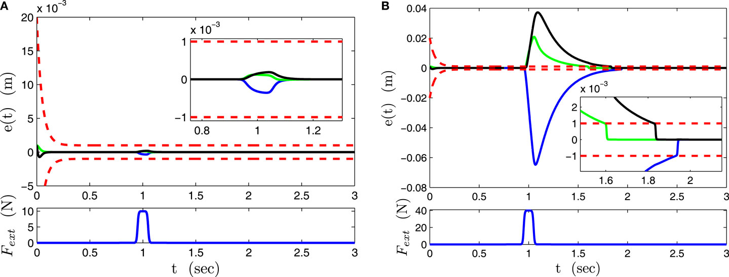
Figure 4. Position error responses in nominal performance and impact reaction mode. Blue line – ex(t). Green line – ey(t). Black line – ez(t). (A) Nominal performance mode. (B) Impact reaction mode.
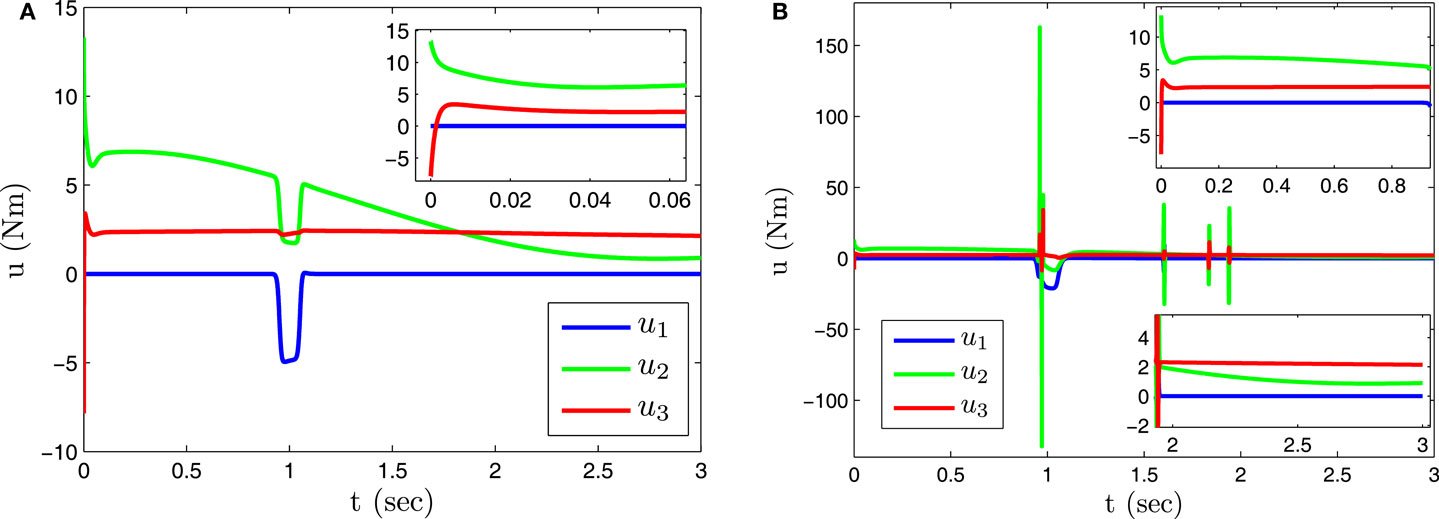
Figure 5. Control input signal in nominal performance and impact reaction mode. (A) Nominal performance mode. (B) Impact reaction mode.
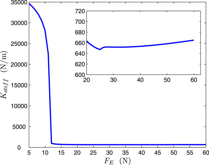
Figure 6. Calculated output stiffness.
Next, we consider joint disturbances arising by an uncertain gravity vector model. Joint disturbances arising from a partially compensated gravity 0.6G(q) result in Cartesian disturbance forces shown in Figure 7B, while error responses together with the response of the system being fully compensated for gravity are shown in Figure 7A. Notice how the system stays in nominal operation respecting preselected performance boundaries despite the presence of disturbances.
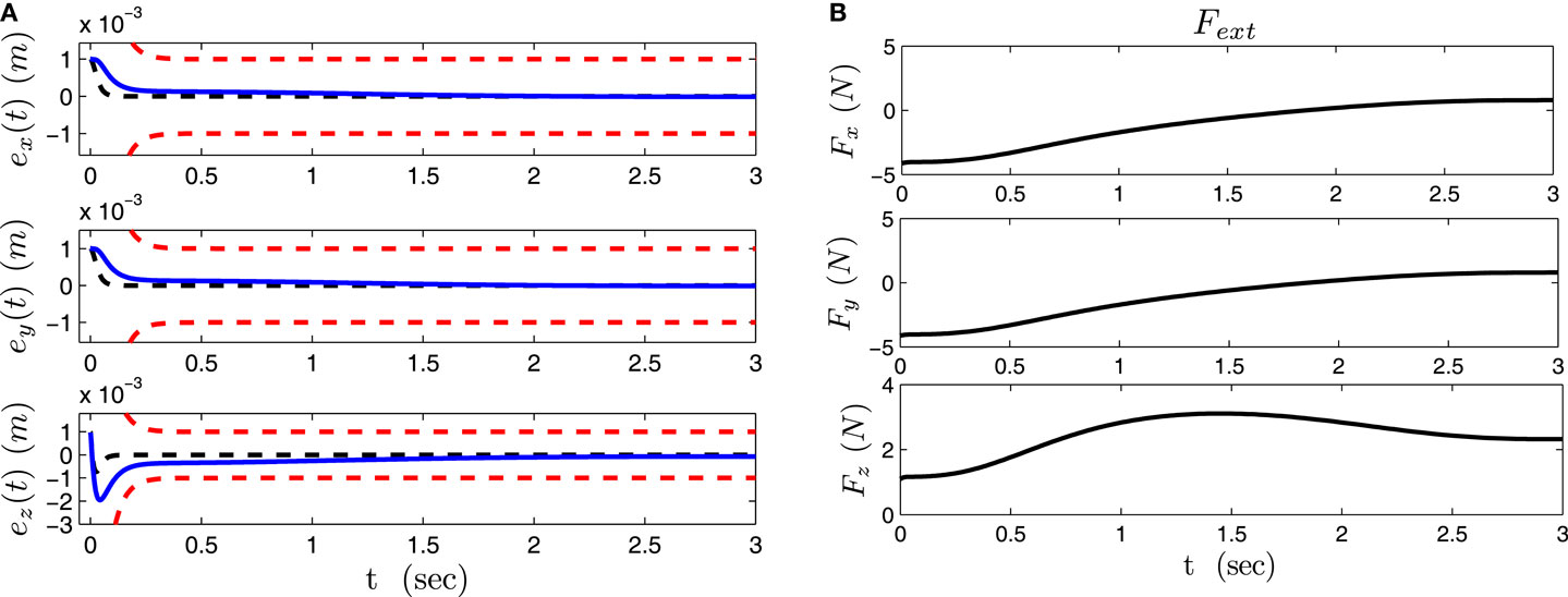
Figure 7. Position error responses and Cartesian disturbance forces due to partial gravity compensation. (A) Position error responses (black dashed line – without disturbance). (B) Cartesian disturbance forces.
Last, we have simulated the case of an impact with an environment modeled as a spring with stiffness of 1000 N/m, obstructing the motion of the arm for 0.5 s. For comparison purposes, we have simulated the case of the robot being under the impedance control scheme of high targeted stiffness as well as a switched impedance between the high and a low stiffness with a delay of 0.001 s (an ideal case examined for comparison purposes) and 0.2 s from the moment of impact in order to account for the time needed for the impact detection and reaction response (a practical switched impedance case). Stiffness values were selected from those appearing in the two modes of operation for the proposed controller and were 28,000 and 600 N/m, respectively. Figure 8 displays the interaction forces developed during the impact. The proposed controller achieves enhanced safety like the practical switched impedance but by smoothly traversing the two stiffness areas. In the proposed controller, the instant the error traverses the boundary is the time of the first interaction force peak and can be regulated by prescribing a different performance bound at steady state. As shown in Figure 9, a lower ρ∞ results in a lower force peak appearing earlier; with a very small value (ρ∞ = 10−9) the interaction force behaves like the ideal switch case.
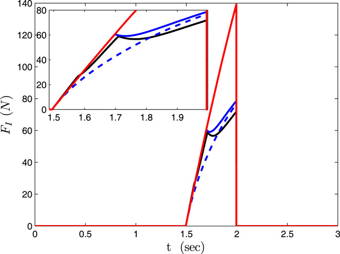
Figure 8. Interaction forces. Black solid line – proposed law. Red solid line – high stiffness impedance controller. Switched impedance controller: Blue solid line −0.2 s delay. Blue dashed line −0.001 s delay.
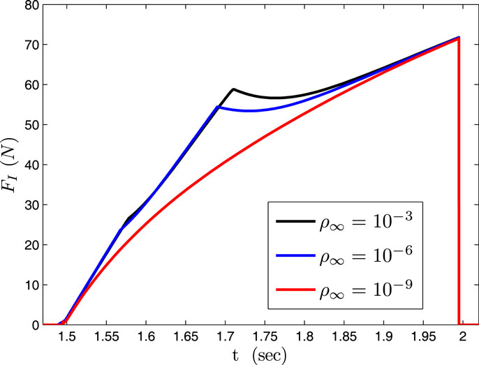
Figure 9. Proposed law. Comparison for different prescribed steady state error bounds ρ∞.
4.2. Experimental Results
Experiments are conducted with a KUKA LWR4+ 7 DOF robotic manipulator. The control law of equation (27) is utilized, ignoring the inertia and Coriolis terms in order to demonstrate the system’s robustness to disturbances due to model uncertainties in the nominal performance mode. The control parameter values are selected as follows: ρi0 = 0.01, ρi∞ = 0.005, and li = 20, ksi = 3, ki = 0.4, i = 1, 2, 3, and Kv = diag (25, 50, 25, 25, 2.5, 0.25, 0.025). In order to demonstrate the apparent Cartesian stiffness of the arm in the impact reaction and nominal mode of operation, two pushing forces of relatively high and low magnitude are exerted by a human to the robot’s end-effector being stationary at position pd = [−0.431 0.6 0.5]T m having initial configuration q = [−7.03 44.45 7.789 −113.26 −8.54 21.27 −8.99]T deg. Figure 10 shows the two pushing forces, at t = 11.6 s and t = 21.6 s, along the y direction, and the respective error displacements. For estimating the apparent stiffness, we have utilized the maximum error displacement with the respective force magnitude (the spike appearing in the first pulse Figure 10 is excluded from this calculation). The apparent Cartesian stiffness is calculated as approximately 204.37 N/m in the impact reaction mode, and approximately 10,073 N/m in nominal operation mode.
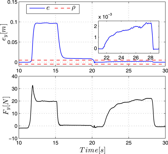
Figure 10. Task position error and imposed force in y-direction.
Next, we consider the case of a human standing in the robot’s way causing an unintentional contact on his back (Figure 11); the human was instructed to move away as soon as he realized the collision. The arm is executing a desired 5th order polynomial trajectory starting from p(0) = [−0.668 −0.058 0.626]T m with configuration q(0) = [0 30 9 −60 −14 22 −9]T deg and moving on a linear path toward the target location pdf = [−0.431 0.6 0.5]T m in 2 s (the maximum velocity is 0.66 m/s). The end-effector path and the position response are shown in Figures 12 and 13 demonstrating the system’s compliance when operating in the impact reaction mode. As KUKA LWR4+ is equipped with torque sensors at each robot joint, joint torque measurements are used by the KUKA software to estimate external forces at the end-effector. Force readings are not utilized in the proposed controller, but they are depicted in Figure 14 together with error deviations in order to demonstrate the drop of stiffness that cannot be analytically obtained. Notice how the force exerted in the x-direction is just below the value causing the transition from the nominal to the reaction mode, as compared to the case in y and z directions. Notice the respective error deviations in the latter case owing to the drop of stiffness. In all cases, impact forces stay relatively low. As the human moves away after impact the robot follows the desired motion with errors returning within the high stiffness prescribed performance region. Figure 15 shows the control effort associated with this case excluding gravity which is provided by the KUKA/FRI (Fast Research Interface) default torque control method.
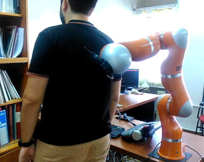
Figure 11. Experiments with KUKA LWR4+.
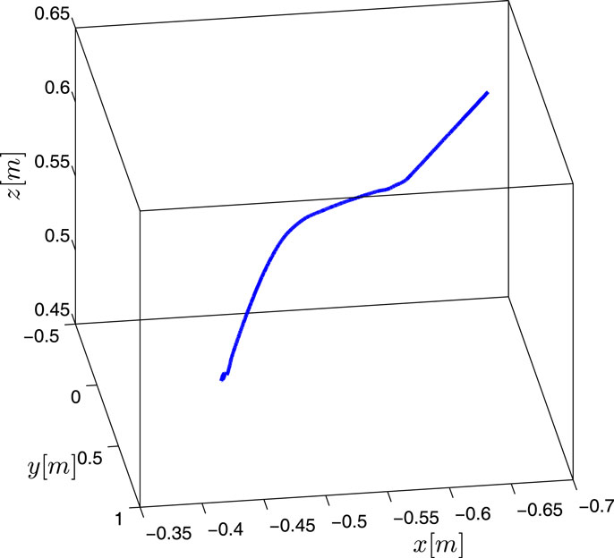
Figure 12. End-effector path.
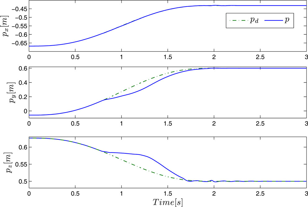
Figure 13. End-effector position.
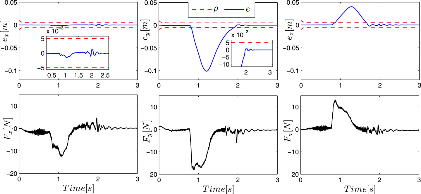
Figure 14. Task position errors and interaction forces.
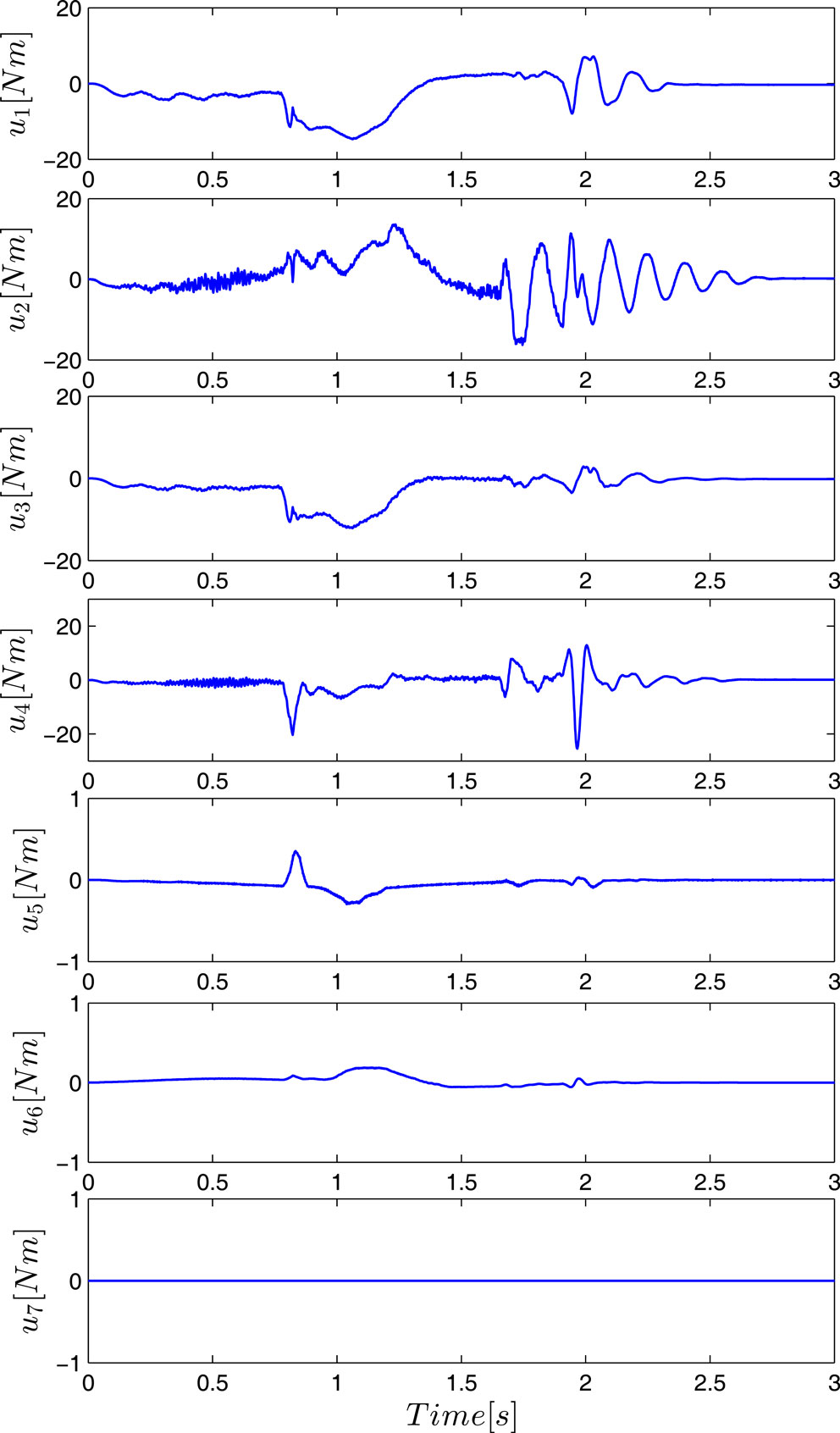
Figure 15. Control input signal not including gravity.
4.3. Discussion
It is well-known that setting a low-desired stiffness in a conventional impedance controller for safety reasons adversely affects performance. On the other hand, high-targeted stiffness in impedance control can achieve a certain tracking quality and robustness but adversely affects human and robot safety. By contrast, the proposed controller addresses both objectives of motion performance and enhanced safety in one scheme. With regards to motion performance quality, it achieves prescribed performance tracking both in transient and steady state respecting performance bounds under disturbances up to a tunable level conceptually separating the nominal operation and the impact reaction modes. Performance in the nominal operation mode has been demonstrated under disturbances arising by partially compensating gravity in simulations and by ignoring the feedforward control terms related to inertial and Coriolis forces in experiments. Thus, the model-based structure in the inner loop does not jeopardize performance. The threshold of the disturbances allowing the operation in the nominal performance mode can be regulated by changing the value of ki. Furthermore, the prescribed performance property of the proposed law facilitates control parameter tuning as this is relaxed into adopting those values that lead to reasonable control effort with respect to magnitude and slew-rate.
Enhanced human and robot safety is on the other hand achieved by operating in the impact reaction mode where the apparent output stiffness is characterized by low values as compared to the high stiffness values characterizing the nominal operation. Stiffness drop was demonstrated in both simulations and experiments where force values shown in Subsections 4.1 and 4.2 were obtained either via a simulated contact or via the force estimation provided by KUKA LWR4+ that is based on torque readings during the impact with a human; they also show how impact forces stay relatively low. The proposed scheme furthermore realizes smooth traversing between the two stiffness areas without control switching or force detection mechanisms that rely on the existence of force measurements or estimates and thus may incur considerable delays. As it has been also demonstrated in simulations, the force peak observed even in the case of a practical switched impedance can be reduced with the proposed controller by reducing the performance bound at steady state, ρ∞. Notice, however, that ρ∞ values cannot be chosen arbitrarily small since they should reflect the accuracy achieved by the measurement device, and ensure that the steady state performance zone is wide enough to accommodate the measurement noise.
5. Conclusion
This work proposes a controller in which the robot output stiffness is self-regulated according to the disturbance magnitude. Moreover, the error is shown to evolve within a predefined performance region in nominal operation mode exhibiting robustness to disturbances up to a tunable threshold. The system reacts stably by reducing its output stiffness under bigger disturbances like those arising from impact, returning to the nominal operation after the disturbance vanishes. The controller achieves a continuous and smooth transition between the two modes without switching, eliminating the need for separate collision detection, and reaction strategies. Simulations and experimental results demonstrate the enhanced safety achieved by the proposed controller under impact with initial impact force magnitudes connected to the prescribed steady state error bounds of the nominal operation mode. Comparison with a practical switched impedance control scheme shows that the proposed control law achieves a slightly better performance without making use of any switching. Future work will further investigate safety under unintentional contacts by taking into account disturbance frequency content.
Author Contributions
I have developed the basic idea for the proposed controller together with my co-author YK, and I have supervised and coordinated the simulated and experimental work, which was performed by my PhD students and co-authors LD and DP.
Conflict of Interest Statement
The authors declare that the research was conducted in the absence of any commercial or financial relationships that could be construed as a potential conflict of interest.
Acknowledgments
This research is co-financed by the EU-ESF and Greek national funds through the operational program “Education and Lifelong Learning” of the National Strategic Reference Framework (NSRF) – Research Funding Program ARISTEIA I under Grant PIROS/506. This work is also partially funded by the Swedish Research Council (VR).
References
Albu-Schaeffer, A., Ott, C., and Petit, F. (2012). “Energy shaping control for a class of underactuated Euler-Langrange systems,” in Proc. 10th Intern. IFAC Symposium on Robot Control (Dubrovnik: International Federation of Automatic Control), 567–574.
Bechlioulis, C. P., Doulgeri, Z., and Rovithakis, G. A. (2012). Guaranteeing prescribed performance and contact maintenance via an approximation free robot force/position controller. Automatica 48, 360–365. doi: 10.1016/j.automatica.2011.07.009
Bechlioulis, C. P., and Rovithakis, G. A. (2008). Robust adaptive control of feedback linearizable MIMO nonlinear systems with prescribed performance. IEEE Trans. Automat. Contr. 53, 2090–2099. doi:10.1109/TAC.2008.929402
Bicchi, A., and Tonietti, G. (2004). Fast and soft arm tactics: dealing with the safety-performance trade-off in robot arms design and control. IEEE Robot. Autom. Mag. 11, 22–33. doi:10.1109/MRA.2004.1310939
Choi, J., Park, S., Lee, W., and Kang, S. C. (2008). “Design of a robot joint with variable stiffness,” in Proceedings – IEEE International Conference on Robotics and Automation (Pasadena, CA: IEEE), 1760–1765.
De Luca, A., Albu-Schaffer, A., Haddadin, S., and Hirzinger, G. (2006). “Collision detection and safe reaction with the DLR-III lightweight manipulator arm,” in Proceedings of the 2006 IEEE/RSJ International Conference on Intelligent Robots and Systems (Beijing: IEEE), 1623–1630.
De Luca, A., and Mattone, R. (2005). “Sensorless robot collision detection and hybrid force/motion control,” in Proceedings of the 2005 IEEE International Conference on Robotics and Automation (Barcelona: IEEE), 999–1004.
De Santis, A., Siciliano, B., De Luca, A., and Bicchi, A. (2010). An atlas of physical humanrobot interaction. Mech. Mach. Theory 43, 253–270. doi:10.1016/j.mechmachtheory.2007.03.003
Erden, M. S., and Tomiyama, T. (2010). Human-intent detection and physically interactive control of a robot without force sensors. IEEE Trans. Robot. 26, 370–382. doi:10.1109/TRO.2010.2040202
Golz, S., Osendorfer, C., and Haddadin, S. (2015). “Using tactile sensation for learning contact knowledge: discriminate collision from physical interaction,” in IEEE International Conference on Robotics and Automation (ICRA) (Seattle, WA: IEEE), 3788–3794.
Haddadin, S., Albu-Schaeffer, A., De Luca, A., and Hirzinger, G. (2008). “Collision detection and reaction: a contribution to safe physical human-robot interaction,” in IEEE International Conference on Intelligent Robotics and System (IROS) (Nice: IEEE), 3356–3363.
Heinzmann, J., and Zelinsky, A. (2003). Quantitative safety guarantees for physical human-robot interaction. Int. J. Rob. Res. 22, 479–504. doi:10.1177/02783649030227004
Karayiannidis, Y., and Doulgeri, Z. (2012). Model-free robot joint position regulation and tracking with prescribed performance guarantees. Rob. Auton. Syst. 60, 214–226. doi:10.1016/j.robot.2011.10.007
Lee, D., and Ott, C. (2011). Incremental kinesthetic teaching of motion primitives using the motion refinement tube. Auton. Robots 31, 115–131. doi:10.1007/s10514-011-9234-3
Magrini, E., Flacco, F., and De Luca, A. (2015). “Control of generalized contact motion and force in physical human-robot interaction,” in IEEE International Conference on Robotics and Automation (ICRA) (Seattle, WA: IEEE), 2298–2304.
Oh, S., Woo, H., and Kong, K. (2014). Frequency-shaped impedance control for safe human-robot interaction in reference tracking application. IEEE/ASME Trans. Mechatron. 19, 1907–1916. doi:10.1109/TMECH.2014.2309118
Siciliano, B., Sciavicco, L., Villani, L., and Oriolo, G. (2010). Robotics: Modelling, Planning and Control. Advanced Textbooks in Control and Signal Processing. London: Springer.
Tsagarakis, N. G., Sardellitti, I., and Caldwell, D. G. (2011). “A new variable stiffness actuator (CompAct-VSA): design and modelling,” in IEEE International Conference on Intelligent Robots and Systems (San Francisco, CA: IEEE), 378–383.
Keywords: motion performance, safety, unintentional contact, control, variable stiffness
Citation: Karayiannidis Y, Droukas L, Papageorgiou D and Doulgeri Z (2015) Robot Control for Task Performance and Enhanced Safety under Impact. Front. Robot. AI 2:34. doi: 10.3389/frobt.2015.00034
Received: 24 September 2015; Accepted: 26 November 2015;
Published: 14 December 2015
Edited by:
Nikola Miskovic, University of Zagreb, CroatiaReviewed by:
Ahmed Chemori, CNRS, FranceArnaud Leleve, Université de Lyon, France
Ivana Palunko, University of Dubrovnik, Croatia
Copyright: © 2015 Karayiannidis, Droukas, Papageorgiou and Doulgeri. This is an open-access article distributed under the terms of the Creative Commons Attribution License (CC BY). The use, distribution or reproduction in other forums is permitted, provided the original author(s) or licensor are credited and that the original publication in this journal is cited, in accordance with accepted academic practice. No use, distribution or reproduction is permitted which does not comply with these terms.
*Correspondence: Zoe Doulgeri, doulgeri@eng.auth.gr