Supervised Autonomy for Exploration and Mobile Manipulation in Rough Terrain with a Centaur-Like Robot
 Max Schwarz*
 Marius Beul
 David Droeschel
 Sebastian Schüller
Arul Selvam Periyasamy
Christian Lenz
Michael Schreiber
Sebastian Schüller
Arul Selvam Periyasamy
Christian Lenz
Michael Schreiber  Sven Behnke
- Autonomous Intelligent Systems, Institute for Computer Science VI, University of Bonn, Bonn, Germany
Planetary exploration scenarios illustrate the need for autonomous robots that are capable to operate in unknown environments without direct human interaction. At the DARPA Robotics Challenge, we demonstrated that our Centaur-like mobile manipulation robot Momaro can solve complex tasks when teleoperated. Motivated by the DLR SpaceBot Cup 2015, where robots should explore a Mars-like environment, find and transport objects, take a soil sample, and perform assembly tasks, we developed autonomous capabilities for Momaro. Our robot perceives and maps previously unknown, uneven terrain using a 3D laser scanner. Based on the generated height map, we assess drivability, plan navigation paths, and execute them using the omnidirectional drive. Using its four legs, the robot adapts to the slope of the terrain. Momaro perceives objects with cameras, estimates their pose, and manipulates them with its two arms autonomously. For specifying missions, monitoring mission progress, on-the-fly reconfiguration, and teleoperation, we developed a ground station with suitable operator interfaces. To handle network communication interruptions and latencies between robot and ground station, we implemented a robust network layer for the ROS middleware. With the developed system, our team NimbRo Explorer solved all tasks of the DLR SpaceBot Camp 2015. We also discuss the lessons learned from this demonstration.
1. Introduction
In planetary exploration scenarios, robots are needed that are capable to autonomously operate in unknown environments and highly unstructured and unpredictable situations. Since human workers cannot be deployed due to economic or safety constraints, autonomous robots have to robustly solve complex tasks without human intervention. To address this need, the German Aerospace Center (DLR) held the DLR SpaceBot Camp 2015.1 Ten German research groups were supported to foster the development of robots, capable of autonomously solving complex tasks that are required in a typical planetary exploration scenario. During the SpaceBot Camp, the robots need to tackle these tasks:
• Find and identify three previously known objects in a planetary-like environment (cup, battery, and base station).
• Take a soil sample of a previously known spot (optional).
• Pick up and deliver the cup and the battery to the base station.
• Assemble all objects.
All tasks had to be completed as autonomously as possible, including perception, manipulation, and navigation, in difficult terrain with slopes up to 15° that need to be traversed and larger untraversable slopes. The overall weight of the deployed robotic system was limited to 100 kg, and the total time for solving all tasks was 60 min. A rough height map with 50 cm resolution of the environment was known prior to the run. The use of any global navigation satellite system (GNSS) was prohibited. No line-of-sight between the robot and the crew was allowed, and communication between the robot and the operators was severely restricted. Data transmission was bidirectionally delayed by 2 s, resulting in a round trip time of 4 s – too large for direct remote control. Furthermore, the uplink connection was blocked entirely after 20 min and 40 min for 4 min each. More details on the SpaceBot Camp itself and our performance are provided in Section 11.
To address the tasks, we used the mobile manipulation robot Momaro (see Figure 1), which is configured and monitored from a ground station. Momaro is equipped with four articulated compliant legs that end in pairs of directly driven, steerable wheels. To perform a wide range of manipulation tasks, Momaro has an anthropomorphic upper body with two 7 degrees of freedom (DOF) manipulators that end in dexterous grippers. This allows for the single-handed manipulation of smaller objects, as well as for two-armed manipulation of larger objects and the use of tools. Through adjustable base height and attitude and a yaw joint in the spine, Momaro has a work space equal to the one of an adult person.
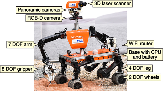
Figure 1. The mobile manipulation robot Momaro taking a soil sample.
The SpaceBot Camp constitutes a challenge for autonomous robots. Since the complex navigation and manipulation tasks require good situational awareness, Momaro is equipped with a 3D laser scanner, multiple color cameras, and an RGB-D camera. For real-time perception and planning, Momaro is equipped with a powerful onboard computer. The robot communicates to a relay at the landing site via WiFi and is equipped with a rechargeable LiPo battery (details provided in Section 3).
The developed system was tested at the SpaceBot Camp 2015. Momaro solved all tasks autonomously in only 20:25 out of 60 min including the optional soil sample. No official ranking was conducted at the SpaceBot Camp, but since we were the only team solving all these tasks, we were very satisfied with the performance. We report in detail on how the tasks were solved. Our developments led to multiple contributions, which are summarized in this article, including the robust perception and state estimation system, navigation and motion–planning modules and autonomous manipulation and control methods. We also discuss lessons learned from the challenging robot operations.
2. Related Work
The need for mobile manipulation has been addressed in the past with the development of a variety of mobile manipulation systems, consisting of robotic arms installed on mobile bases with the mobility provided by wheels, tracks, or leg mechanisms. Several research projects exist that use purely wheeled locomotion for their robots (Mehling et al., 2007; Borst et al., 2009). In the previous work, we developed NimbRo Explorer (Stückler et al., 2015), a six-wheeled robot equipped with a 7 DOF arm designed for mobile manipulation in rough terrain, encountered in planetary exploration scenarios.
Wheeled rovers provide optimal solutions for well structured and relatively flat environments; however, outside of these types of terrains, their mobility quickly reaches its limits. Often they can only overcome obstacles smaller than the size of their wheels. Compared to wheeled robots, legged robots are more complex to design, build, and control (Raibert et al., 2008; Roennau et al., 2010; Semini et al., 2011; Johnson et al., 2015), but they have obvious mobility advantages when operating in unstructured terrains and environments. Some research groups have started investigating mobile robot designs that combine the advantages of both legged and wheeled locomotion, using different coupling mechanisms between the wheels and legs (Adachi et al., 1999; Endo and Hirose, 2000; Halme et al., 2003). In the context of the DARPA Robotics Challenge, multiple teams (beside ours) used hybrid locomotion designs (Hebert et al., 2015; Stentz et al., 2015). In particular, the winning team KAIST (Kim and Oh, 2010; Cho et al., 2011) used wheels on the knees of their humanoid robot to move quickly and safely between different tasks on flat terrain.
In 2013, DLR held a very similar SpaceBot competition which encouraged several robotic developments (Kaupisch et al., 2015). Heppner et al. (2015) describe one of the participating systems, such as the six-legged walking robot LAURON V. LAURON is able to overcome challenging terrain, although its six legs limit the locomotion speed in comparison to wheeled robots. As with our system, the software architecture is based on the Robot Operating System [ROS (Quigley et al., 2009)].
Sünderhauf et al. (2014) developed a cooperative team of two-wheeled robots, named Phobos and Deimos. The straightforward, rugged design with skid steering performed well, compared to more complicated locomotion approaches. We made the same observation in our participation at the SpaceBot Competition 2013 and opted to include wheels (opposed to a purely legged concept) in the Momaro robot. In the 2013 competition, Phobos and Deimos mainly had communication issues such that the ground station crew could neither stop Phobos from colliding with the environment nor start Deimos to resume the mission. These problems highlight why we spent considerable effort on our communication subsystem (see Section 9) to ensure that the operator crew has proper situational awareness and is able to continuously supervise the robotic operation.
Schwendner et al. (2014) and Joyeux et al. (2014) discuss the six-wheeled Artemis rover. Artemis is able to cope with considerable terrain slopes (up to 45°) through careful mechanical design. In contrast, Momaro has to employ active balancing strategies (see Section 6) to prevent tipping over due to its high center of mass. The authors emphasize the model-driven design of both hardware and software. The latter is partly ROS based but also has modules based on the Rock framework. Artemis demonstrated its navigation capabilities in the 2013 competition, but eventually its navigation planners became stuck in front of a trench, again highlighting the need to design systems with enough remote access, so that problems can be diagnosed and fixed remotely.
A few articles on the SpaceBot Camp 2015 are already available. Kaupisch and Fleischmann (2015) describe the event and report briefly on the performances of all teams. Wedler et al. (2015) present the general design of their Lightweight Rover Unit (LRU), which competed in the SpaceBot Camp 2015, successfully solving all tasks except the optional soil sample task. The LRU is a four-wheeled rover with steerable wheels, similar to Momaro’s drive. Comparable to our flexible legs, the suspension uses both active and passive mechanisms. However, the LRU wheels are rigidly coupled with pairs, and the base height cannot be adapted. Overall, the LRU seems geared toward building a robust and hardened rover for real missions, while Momaro’s components are not suitable for space. On the other hand, Momaro can solve tasks requiring stepping motions and is capable of dexterous bimanual manipulation.
In our previous work, we describe the Explorer system used in the 2013 competition (Stückler et al., 2015) and its local navigation system (Schwarz and Behnke, 2014). Compared to the 2013 system, we improve on the
• capabilities of the mechanical design (e.g., execution of stepping motions or bimanual manipulation),
• grade of autonomy (execution of full missions, including assembly tasks at the base station),
• situational awareness of the operator crew, and
• robustness of network communication.
The local navigation approach has moved from a hybrid laser scanner and RGB-D system on three levels to a laser scanner-only system on two levels – allowing operation in regions where current RGB-D sensors fail to measure distance (e.g., in direct sunlight).
In contrast to many other systems, Momaro is capable of driving omnidirectionally, which simplifies navigation in restricted spaces and allows us to make small lateral positional corrections faster. Furthermore, our robot is equipped with six limbs, two of which are exclusively used for manipulation. The use of four legs for locomotion provides a large and flexible support polygon when the robot is performing mobile manipulation tasks. The Momaro system demonstrated multiple complex tasks under teleoperation in the DARPA Robotics Challenge (Schwarz et al., 2016).
Supervised autonomy has been proposed as a development paradigm by Cheng and Zelinsky (2001), who shift basic autonomous functions like collision avoidance from the supervisor back to the robot, while offering high-level interfaces to configure the functions remotely. In contrast to human-in-the-loop control, supervised autonomy is more suited toward the large latencies involved in space communications. Gillett et al. (2001) use supervised autonomy in the context of an unmanned satellite servicing system that must perform satellite capture autonomously. The survey conducted by Pedersen et al. (2003) not only highlights the (slow) trend in space robotics toward more autonomous functions but also points out that space exploration will always have a human component, if only as consumers of the data produced by the robotic system. In this manner, supervised autonomy is also the limit case of sensible autonomy in space exploration.
3. Mobile Manipulation Robot Momaro
3.1. Mechanical Design
Our mobile manipulation robot Momaro (see Figure 1) was constructed with several design goals in mind:
• universality,
• modularity,
• simplicity, and
• low weight.
In the following, we detail how we address these goals.
3.1.1. Universality
Momaro features a unique locomotion design with four legs ending in steerable wheels. This design allows to drive omnidirectionally and to step over obstacles or even climb. Since it is possible to adjust the total length of the legs, Momaro can manipulate obstacles on the ground, as well as reach to heights of up to 2 m. Momaro can adapt to the slope of the terrain through leg length changes.
On its base, Momaro has an anthropomorphic upper body with two adult-sized 7 DOF arms, enabling it to solve complex manipulation tasks. Attached to the arms are two 8-DOF dexterous hands consisting of four fingers with two segments each. The distal segments are 3D printed and can be changed without tools for easy adaption to a specific task. For the SpaceBot Camp, we designed distal finger segments that maximize the contact surface to the SpaceBot objects: the finger tips are shaped to clamp around the circumference of the cylindrical cup object (see Figure 3). The box-shaped battery object is first grasped using the proximal finger segments, and then locked in-place with the distal finger segments as soon as it is lifted from the ground.
The upper body can be rotated around the spine with an additional joint, thus increasing the workspace. Equipped with these various DOF, Momaro can solve most diverse tasks. If necessary, Momaro is even able to use tools. We showed this ability by taking a soil sample with a scoop at the SpaceBot Camp (see Figure 2).
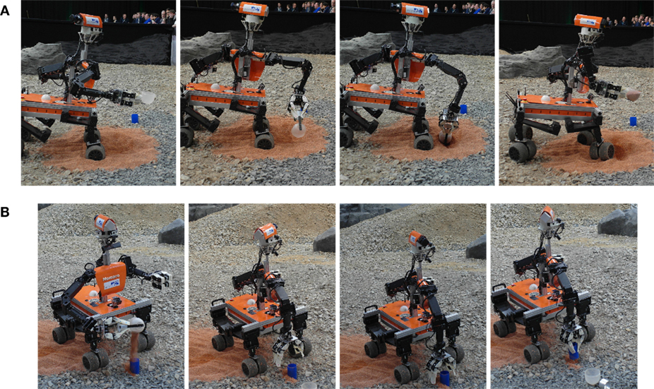
Figure 2. Manipulation capabilities. (A) Momaro is using a scoop to take a soil sample. (B) After filling the blue cup with previously scooped soil, Momaro discards the scoop and grasps the cup to deliver it to a base station.
3.1.2. Modularity
All joints of Momaro are driven by Robotis Dynamixel actuators, which offer a good torque-to-weight ratio. While the finger actuators and the rotating laser scanner actuator are of the MX variant, all others are Dynamixel Pro actuators. Figure 3 gives an overview of the DOF of Momaro. For detailed information on Momaro’s actuators, we refer to Schwarz et al. (2016).

Figure 3. Hardware components. (A) Sensor head carrying 3D laser scanner, IMU, four cameras, and an RGB-D camera. (B) The 8-DOF hand has specialized fingers for grasping the objects. (C) Kinematic tree of one half of Momaro. The hand is excluded for clarity. Proportions are not to scale. (D) The front left leg. The red lines show the axes of the six joints. (E) Simplified overview of the electrical components of Momaro. Sensors are colored green, actuators blue, and other components red. We show USB 2.0 data connections (red), LAN connections (dotted, blue), and the low-level servo bus system (dashed, green).
Using similar actuators for every DOF simplifies maintenance and repairs. For example, at the SpaceBot Camp, one of the shoulder actuators failed shortly before our run. A possibility could have been to repair the vital shoulder using a knee actuator, since the knees were hardly used in this demonstration. Fortunately, we acquired a spare actuator in time. Details can be found in Section 11.
3.1.3. Simplicity
For Momaro, we chose a four-legged locomotion design over bipedal approaches. The motivation for this choice was mainly the reduction in overall complexity, since balance control and fall recovery are not needed. Each leg has three degrees of freedom in hip, knee, and ankle. To reach adequate locomotion speeds on flat terrain, where steps are not needed, the legs are equipped with steerable wheel pairs. For omnidirectional driving, the wheel pairs can be rotated around the yaw axis, and each wheel can be driven independently. The legs also provide passive adaption to the terrain, as the leg segments are made from flexible carbon fiber and act as springs. The front legs have a vertical extension range of 40 cm. For climbing inclines, the hind legs can be extended 15 cm further. Using these features, obstacles lower than approximately 5 cm can be ignored.
3.1.4. Low Weight
Momaro is relatively lightweight (58 kg) and compact (base footprint 80 cm × 70 cm). During development and deployment, this is a strong advantage over heavier robots, which require large crews and special equipment to transport and operate. In contrast, Momaro can be carried by two people. In addition, it can be transported in standard suitecases by detaching the legs and torso.
3.2. Sensing
Momaro carries a custom-built 3D rotating laser scanner (see Figure 3) for simultaneous mapping and localization (see Section 5). As with previous robots (Stückler et al., 2015), a Hokuyo UTM-30LX-EW laser scanner is mounted on a slip ring actuated by a Robotis Dynamixel MX-64 servo, which rotates it around the vertical axis. For state estimation and motion compensation during a 3D scan, a PIXHAWK IMU is mounted close to the laser scanner.
For object detection, Momaro features an ASUS Xtion Pro Live RGB-D camera. Since Momaro’s origins are in teleoperated scenarios (Schwarz et al., 2016), it also carries seven color cameras – three panoramic cameras and one downward-facing wide-angle camera mounted on the head, one camera mounted in each hand, and one wide-angle camera below the base. In a supervised autonomy scenario, these cameras are mainly used for monitoring the autonomous operation.
3.3. Electronics
Figure 3 gives an overview of the electrical components of Momaro. For onboard computation, an off-the-shelf mainboard with a fast CPU (Intel Core i7-4790K @4–4.4 GHz) and 32 GB RAM is installed in the base. Communication with up to 1300 Mbit/s to the ground station is achieved through a NETGEAR Nighthawk AC1900 WiFi router. The hot-swappable six-cell 355 Wh LiPo battery yields around 1.5–2 h run time. Momaro can also run from a power supply for more comfortable development.
For more details on Momaro’s hardware design, we refer to Schwarz et al. (2016).
4. Software Architecture
Both the Momaro robot and the scenarios we are interested will require highly sophisticated software. To retain modularity and maintainability and encourage code re-use, we built our software on top of the popular ROS [Robot Operating System (Quigley et al., 2009)] middleware. ROS provides isolation of software components into separate nodes (processes) and inter- and intraprocess communication via a publisher/subscriber scheme. ROS has seen widespread adoption in the robotics community and has a large collection of freely available open-source packages.
To support the multitude of robots and applications in our group,2 we have a set of common modules, implemented as Git repositories. These modules (blue and green in Figure 4) are used across projects as needed. On top of the shared modules, we have a repository for the specific application (e.g., DLR SpaceBot Camp 2015, yellow in Figure 4), containing all configuration, and code required exclusively by this application. The collection of repositories is managed by the wstool ROS utility.
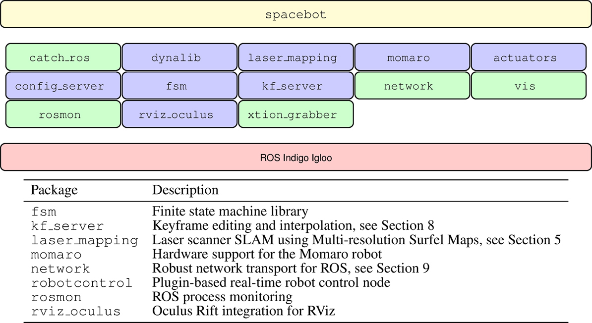
Figure 4. Organization of software modules. At the base, the ROS middleware is used. The blue colored boxes correspond to software modules, shared across robots, projects, and competitions. Finally, the spacebot module contains software, specific to the SpaceBot Camp. Modules colored in green have been released as open source, see https://github.com/AIS-Bonn.
Protection against unintended regressions during the development process is best gained through unit tests. The project-specific code is hard to test, though, since it is very volatile, on the one hand, and testing would often require full-scale integration tests using a simulator, on the other hand. This kind of integration tests have not been developed yet. In contrast, the core modules are very stable and can be augmented easily with unit tests. Unit tests in all repositories are executed nightly on a Jenkins server, which builds the entire workspace from scratch, gathers any compilation errors and warnings, and reports test results.
5. Mapping and Localization
For autonomous navigation during a mission, our system continuously builds a map of the environment and localizes within this map. To this end, 3D scans of the environment are aggregated in a robot-centric local multiresolution map. The 6D sensor motion is estimated by registering the 3D scan to the map using our efficient surfel-based registration method (Droeschel et al., 2014a). In order to obtain an allocentric map of the environment – and to localize in it – individual local maps are aligned to each other using the same surfel-based registration method. A pose graph that connects the maps of neighboring key poses is optimized globally. Figure 5 outlines our mapping system.
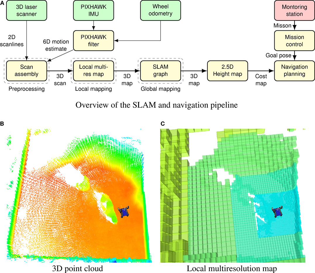
Figure 5. SLAM and navigation architecture. (A) Overview of our mapping, localization, and navigation system. After filtering spurious measurements and assembling 3D point clouds (Section 5.1), measurements are aggregated in a robot-centric multiresolution map (Section 5.2) using surfel-based registration. Keyframe views of local maps are registered against each other in a SLAM graph (Section 5.3). A 2.5D height map is used to assess drivability. A standard 2D grid-based approach is used for planning (Section 6). (B) 3D points stored in the map on the robot. Color encodes height from ground. (C) The robot-centric multiresolution map with increasing cell size from the robot center. Color indicates the cell length from 0.25 m on the finest resolution to 2 m on the coarsest resolution.
5.1. Preprocessing and 3D Scan Assembly
Before assembling 3D point clouds from measurements of the 2D laser scanner, we filter out the so-called jump edges. Jump edges arise at transitions between two objects and result in spurious measurements. These measurements can be detected by comparing the angle between neighboring measurements and are removed from the raw measurements of the laser scanner. The remaining measurements are then assembled to a 3D point cloud after a full rotation of the scanner. During assembly, raw measurements are undistorted to account for motion of the sensor during rotation.
We estimate the motion of the robot during a full rotation of the sensor from wheel odometry and measurements from the PIXHAWK IMU mounted in the sensor head. Rotational motions are estimated from gyroscopes and accelerometers, whereas linear motions are estimated by filtering wheel odometry with linear acceleration from the IMU. The resulting motion estimate is applied to the remaining measurements by means of spherical linear interpolation.
5.2. Local Mapping
The filtered and undistorted 3D point clouds are aggregated in a robot-centric multiresolution grid map as shown in Figure 5. The size of the grid cell increases with the distance from the robot, resulting in a fine resolution in the direct workspace of the robot and a coarser resolution farther away. The robot-centric property of the map is maintained by shifting grid cells according to the robot motion – efficiently implemented by using circular buffers. Using robot-centric multiresolution facilitates efficiency in terms of memory consumption and computation time.
Besides 3D measurements from the laser scanner, each grid cell stores an occupancy probability – allowing to distinguish between occupied, free, and unknown areas. Similar to Hornung et al. (2013), we use a beam-based inverse sensor model and raycasting to update the occupancy probability of a cell. For every measurement in the 3D scan, we update the occupancy information of cells on the ray between the sensor origin and the endpoint.
After a full rotation of the laser, the newly acquired 3D scan is registered to the so far accumulated map to compensate for drift of the estimated motion. For aligning a 3D scan to the map, we use our surfel-based registration method (Droeschel et al., 2014a) – designed for this data structure, it leverages the multiresolution property of the map and gains efficiency by summarizing 3D points to surfels that are used for registration. Measurements from the aligned 3D scan replace older measurements in the map and are used to update the occupancy information.
5.3. Allocentric Mapping
We incorporate measurements from the wheel odometry, IMU, and local registration results to track the pose of the robot over a short period of time. To overcome drift and to localize the robot with respect to a fixed frame, we build an allocentric map from the robot-centric multiresolution maps acquired at different view poses (Droeschel et al., 2014b).
We construct a pose graph consisting of nodes, which are connected by edges. Each node corresponds to a view pose and its local multiresolution map. Nearby nodes are connected by edges, modeling spatial constraints between two nodes. Each spatial constraint is a normally distributed estimate with mean and covariance. An edge describes the relative position between two nodes, arising from aligning two local multiresolution maps with each other. Similar to the alignment of a newly acquired 3D scan, two local multiresolution maps are aligned by surfel-based registration. Each edge models the uncertainty of the relative position by its information matrix, which is established by the covariance from registration. A new node is generated for the current view pose, if the robot moved sufficiently far.
In addition to edges between the previous node and the current node, we add spatial constraints between close-by nodes in the graph that are not in temporal sequence. By adding edges between close-by nodes in the graph, we detect loop closures. Loop closure allows us to minimize drift from accumulated registration errors, for example, if the robot traverses unknown terrain and reenters a known part of the environment.
From the graph of spatial constraints, we infer the probability of the trajectory estimate given all relative pose observations using the g2o framework (Kuemmerle et al., 2011). Optimization is performed when a loop closure has been detected, allowing for online operation.
5.4. Localization
While traversing the environment, the pose graph is extended and optimized whenever the robot explores previously unseen terrain. We localize toward this pose graph during mission to estimate the pose of the robot in an allocentric frame. When executing a mission, e.g., during the SpaceBot Camp, the robot traverses goal poses w.r.t. this allocentric frame.
To localize the robot within the allocentric pose graph, the local multiresolution map is registered toward the closest node in the graph. By aligning the dense local map to the pose graph – instead of the relative sparse 3D scan – we gain robustness, since information from previous 3D scans is incorporated. The resulting registration transform updates the allocentric robot pose. To gain allocentric localization poses during acquisition of the scan, the 6D motion estimate from wheel odometry, and IMU is used to extrapolate the last allocentric pose.
During the SpaceBot Camp, we assumed that the initial pose of the robot was known, either by starting from a predefined pose or by means of manually aligning our allocentric coordinate frame with a coarse height map of the environment. Thus, we could navigate to goal poses in the coarse height map by localizing toward our pose graph.
5.5. Height Mapping
As a basis for assessing drivability, the 3D map is projected into a 2.5D height map, shown in Figure 6. In case multiple measurements are projected into the same cell, we use the measurement with median height. Gaps in the height map (cells without measurements) are filled with are local weighted mean if the cell has at least two neighbors within a distance threshold (20 cm in our experiments). This provides a good approximation of occluded terrain until the robot is close enough to actually observe it. After filling gaps in the height map, the height values are spatially filtered using the fast median filter approximation using local histograms (Huang et al., 1979). The resulting height map is suitable for navigation planning (see Section 6).
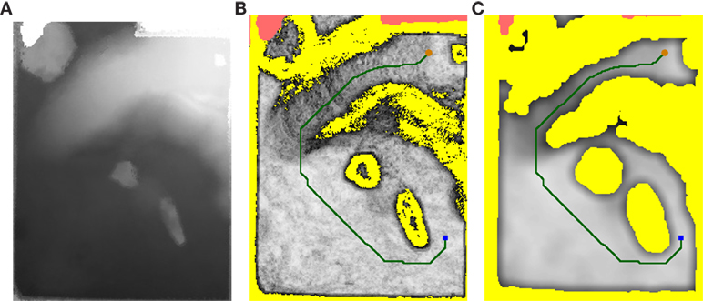
Figure 6. Navigation planning. (A) 2.5D height map generated by projecting the 3D map. (B) Calculated traversability costs for each cell. (C) Inflated costs used for A* path planning. The orange dot represents the current robot position, the blue square represent the target position. Yellow regions represent absolute obstacles, red regions indicate missing measurements.
6. Navigation
Our autonomous navigation solution consists of two layers: the global path planning layer and the local trajectory planning layer. Both planners are fed with cost maps calculated from the aggregated laser measurements.
6.1. Local Height Difference Maps
Since caves and other overhanging structures are the exception on most planetary surfaces, the 2.5D height map generated in Section 5.5 suffices for autonomous navigation planning.
The 2.5D height map H is transformed into a multi-scale height difference map. For each cell (x, y) in the horizontal plane, we calculate local height differences Dl at multiple scales l. We compute Dl (x, y) as the maximum difference to the center cell (x, y) in a local l-window:
H(u, v) values of NaN are ignored. In the cases where the center cell H (x, y) itself is not defined, or there are no other defined l-neighbors, we assign Dl (x, y): = NaN. Small, but sharp obstacles show up on the Dl maps with lower l scales. Larger inclines, which might be better to avoid, can be seen on the maps with a higher l value.
6.2. Path Planning
During the SpaceBot Camp, we used the standard ROS navfn3 planner. Afterward, we replaced it with a custom A* planner to consider gradual costs fully, which the ROS planner was not designed to do. We transform the height difference map into a cost map that can be used for path planning.
A combined difference map, is generated by linear combination of different Dl maps to comprise information about smaller obstacles and larger inclines. The summands from the D3 and D6 maps are constrained to a response of 1/2 to prevent the creation of absolute obstacles from a single scale alone. The smallest scale D1 is allowed to create absolute obstacles, since sharp obstacles pose great danger to the robot:
The λ1, λ3, and λ6 parameter values for drivability computation were empirically determined as 2.2, 3.6, and 2.5, respectively.
6.2.1. Global Path Planning
For global path planning, we implemented an A* graph search on the 2D grid map. The Euclidean distance (multiplied with the minimum cost in the grid map) is used as the heuristic function for A*. This planning does not account for the robot foot print and considers the robot as just a point in the 2D grid. To ensure the generation of a safe path, we inflate obstacles in the cost map to account for the risk closer to obstacles. The inflation is done in two steps. The cells within the distance of robot radius from absolute obstacles are elevated to absolute obstacle cost, yielding cost map . Then for all other cells, we calculate local averages to produce costs DD that increase gradually close to obstacles:
Figure 6 shows a planned path on the height map acquired during our mission at the SpaceBot Camp.
6.2.2. Local Trajectory Rollout
The found global path needs to be executed on a local scale. To this end, we use the standard ROS dwa_local_planner4 package, which is based on the Dynamic Window Approach (Fox et al., 1997). The dwa_local_planner accounts for the robot foot print, so cost inflation is not needed.
In order to prevent oscillations due to imperfect execution of the planned trajectories, we made some modifications to the planner. The dwa_local_planner plans trajectories to reach the given goal pose (x, y, θ) first in 2D (x, y) and then rotates in-place to reach θ (this is called “latching” behavior). Separate cartesian and angular tolerances determine when the planner starts turning and when it reports navigation success. We modified the planner to keep the current “latching” state even when a new global plan is received (every 4 s), as long as the goal pose does not change significantly. We also wrote a simple custom recovery behavior that first warns the operator crew that the robot is stuck and then executes a fixed driving primitive after a timeout.
6.3. Omnidirectional Driving
The wheel positions r(i) relative to the trunk determine not only the footprint of the robot but also the orientation and height of the robot trunk. During autonomous operation, the wheel positions are kept in a configuration with a base height.
Either autonomous navigation or manual operator input generates a velocity command w = (vx, vy, ω) with horizontal linear velocity v and rotational velocity ω around the vertical axis. The velocity command is first transformed into the local velocity at each wheel i:
where r(i) is the current position of wheel i relative to the base. The kinematic velocity component allows simultaneous leg movement while driving. The wheels rotates to yaw angle first and then moves with the velocity . While driving, the robot continuously adjusts the orientation of the ankle, using IMU information to keep the axis vertical and thus retains omnidirectional driving capability.
6.4. Base Orientation Control
To prevent the robot from pitching over on the high-incline areas in the arena, we implemented a pitch control mechanism. The pitch angle of the robot is continuously measured using the IMU. We then use a simple proportional controller to compensate for the disturbance. With the commanded angle w, disturbance z, controller gain Kp, plant gain Ks, and plant disturbance gain Ksz, the steady-state error eb of the linearized proportional plant evolves with
Since the incline is directly measured, Ks = 1 and Ksz = 1. We found Kp = 0.8 to sufficiently stabilize for inclines present at the SpaceBot Camp. When driving up the ramp with z ≈ 15°, and setpoint w = 0° the resulting error (robot pitch) is eb ≈ 8.3°.
We found that this compensation enables Momaro to even overcome inclines greater than 20° without pitching over. Due to the lack of integral control, the robot is even (eb = 0°) only on a completely flat surface. Since this poses no balance problem, there is no need for integral control.
7. Object Perception
For approaching objects and adapting motion primitives to detected objects, RGB images, and RGB-D point clouds from the wide-angle camera and ASUS Xtion camera, mounted on the sensor head are used. We differentiate between object detection (i.e., determining an approximate object position) and object registration (i.e., determining the object pose accurately).
The objects provided by DLR are color coded. We classify each pixel by using a precomputed lookup table in YUV space. The lookup table is generated from a collection of ellipses for each color class in UV space (see Figure 7), and lower/upper limits in brightness (Y). Thus, we assume that the object color measurements are governed by a Gaussian mixture model in the UV plane. In practice, a single ellipse sufficed for each of the SpaceBot Camp objects.
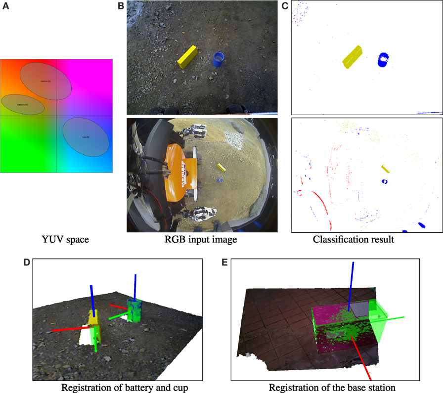
Figure 7. Object perception. (A) Classification ellipses in UV space. (B) RGB input image (first row: Xtion camera, second row: RGB wide-angle camera). (C) Pixel classes (white = unknown). (D) RGB-D point cloud showing the cup and battery objects on SpaceBot Camp terrain. The registered models are shown in green. (E) Registration of the base station. Although neither the left nor the right face is visible, the pose ambiguity is resolved correctly.
When approaching an object, object detection is initially performed with the downward-facing wide-angle camera mounted on the sensor head (see Figure 7). Using the connected component algorithm, we obtain object candidate clusters of same-colored pixels. An approximate pinhole camera model calculates the view ray for each cluster. Finally, the object position is approximated by the intersection of the view ray with the local ground plane. The calculated object position is precise enough to allow approaching the object until it is in the range of other sensors.
As soon as the object is in range of the head-mounted ASUS Xtion camera, the connected component algorithm can also take Cartesian distance into account. We use the PCL implementation of the connected component algorithm for organized point clouds. Since the depth measurements allow us to directly compute the cluster centroid position, and the camera is easier to calibrate, we can approach objects much more precisely using the RGB-D camera.
When the object is close enough, we use registration of a CAD model to obtain a precise object pose (see Figure 7). Since color segmentation often misses important points of the objects, we perform a depth-based plane segmentation using RANSAC and Euclidean clustering as detailed by Holz et al. (2011) to obtain object clusters. The clusters are then registered using Generalized ICP (Segal et al., 2009).
ICP approaches often have problems with partially observed box shapes. For example, only the front and the top face of a box may be visible if the box is partially outside of the camera view frustum. To resolve the resulting ambiguity, we initialize the ICP pose using PCA under the assumption that the visible border of the object which is close to the image border is not an actual object border but is caused by the camera view frustum. In practice, this problem particularly occurs with the large base station object (see Figure 7).
The ICP pose is then normalized respecting the symmetry axes/planes of the individual object class. For example, the cup is symmetrical around the Z axis, so the X axis is rotated such that it points in the robot’s forward direction (see Figure 7).
8. Manipulation
Since Momaro is a unique prototype, the time used for development and testing had to be balanced between individual submodules. To reduce the need for access to the real robot, we made extensive use of simulation tools. For manipulation tasks, we developed a Motion Keyframe Editor GUI to design motion primitives offline. Finished motions are then tested and finalized on the real robot with the original objects to be manipulated in the field. We show the Motion Keyframe Editor GUI in Figure 8. With its help, we designed dedicated motions for all specific tasks in the SpaceBot Camp. We give an overview of our custom motions and their purpose in Figure 8.
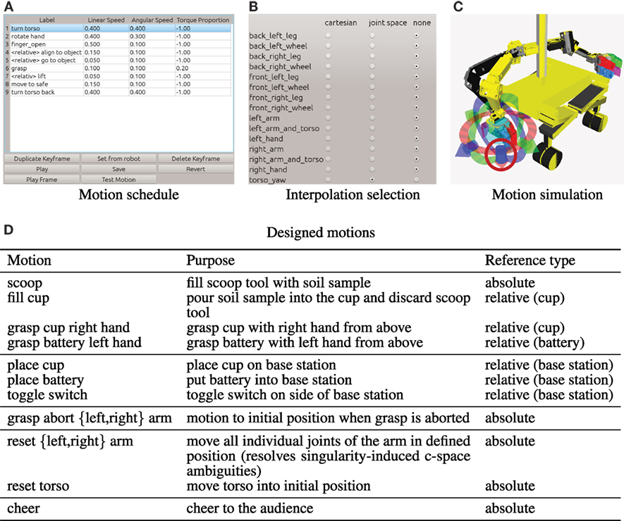
Figure 8. Keyframe editor GUI. (A) Motions are designed step by step and can be absolute or relative to perceived objects. (B) The user can select which joint groups are included in the currently edited keyframe and if interpolation between keyframes is Cartesian or joint space. (C) The real position of the robot is indicated in black. The currently edited keyframe target is shown in yellow. Interactive markers can be used to modify the keyframe pose in 6D (here only for the right hand). A model of the cup (blue, circled red) is placed in front of the robot to assist designing relative motions. (D) Overview of the custom motions designed for the SpaceBot Camp 2015.
8.1. Kinematic Control
We use straightforward kinematic control for Momaro (see Figure 9). Both arms and the torso yaw joints are considered independently.
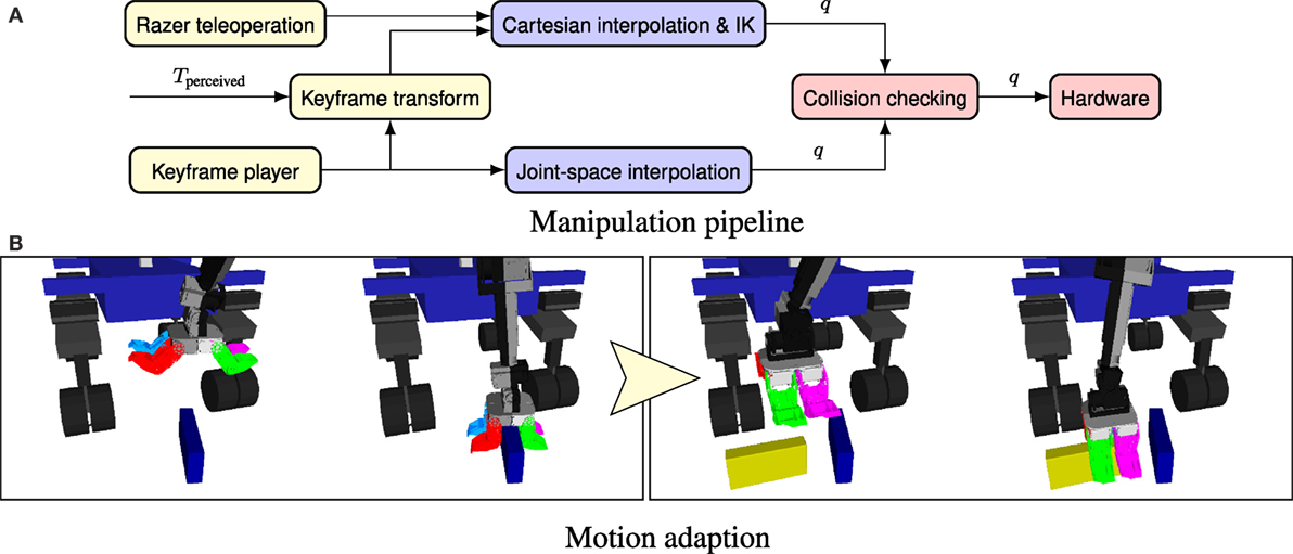
Figure 9. Object manipulation. (A) Kinematic control architecture for Momaro. Joint configurations can be generated using magnetic trackers or the keyframe player. Cartesian poses in keyframes can be adapted to a measured pose p. The interpolated configurations Tperceived are checked for collisions before they are sent to the hardware. (B) Grasping objects dynamically using motion adaption. Left: the blue reference object is grasped as the primitive was designed in the Keyframe editor. Right: the primitive is automatically adapted to the perceived pose of the yellow object.
A goal configuration is specified by telemanipulation (see Section 10) or predefined keyframe sequences either in Cartesian or in joint space. To interpolate between current and goal configuration, the Reflexxes Motion Library (Kröger, 2011) is used. Goals for different limbs can be defined concurrently; the interpolation is configured in a way that goals for all limbs are reached simultaneously. Cartesian poses are converted to joint-space configurations, using inverse kinematics after interpolation. We use the selectively damped least squares approach (SDLS) described by Buss and Kim (2005) to calculate the inverse kinematics of the arms. Before the configurations are sent to the hardware controllers for execution, they are checked for self-collisions using the MoveIt! Library.5 Detecting a collision will abort motion execution. For safety reasons, different methods of manipulation control (i.e., telemanipulation and the keyframe player) will preempt each other.
8.2. Motion Adaption
Since it is often impossible or too slow to precisely approach an object in all 6 dimensions, we relax the assumption of absolute positioning. Motions can be designed around a reference object Trefernce. When the motion is executed, the predefined endeffector pose Tendeffector is transformed in selected keyframes i to match the perceived object Tperceived:
Figure 9 shows how a motion, designed relative to a reference object, is adapted to a perceived object pose to account for imprecise approach of the object.
As described in Section 7, the perceived objects are represented in a canonical form, removing all ambiguities resulting from symmetries in the original objects. For example, the rotation-symmetric cup is always grasped using the same yaw angle. After adaption, the Cartesian keyframes are interpolated as discussed earlier.
9. Communication
Communication between the ground station and a planetary rover is typically very limited – in particular, it has high latency due to the speed of light and the large distances involved. The SpaceBot Camp addressed this limitation by imposing several constraints on the network link:
• Packets were delayed by 2 s in each direction, as expected to occur on a lunar mission,
• the uplink from the ground station to the robot could only be opened for 5 min at a time, and
• the 60-min schedule included two 4-min windows where uplink communication was not possible (e.g., due to planetary occlusions).
Furthermore, our system uses a wireless data link inside the arena, which introduces packet loss.
The main idea of our communication system is to minimize latency by exploiting the different characteristics of the local wireless link inside the arena and the simulated inter-planetary network.
9.1. Communication Architecture
Our communication architecture is shown in Figure 10. The DLR-provided network emulator is the central element limiting all communication between robot and operator crew. To be able to exploit the different link characteristics, we place an additional field computer between the network emulator and the robot. Thus, it is connected to the network emulator via a reliable Ethernet connection and communicates directly with the robot over WiFi. As the WiFi link is unreliable, but has low latency, while the network emulator link is reliable, but has high latency, this places the field computer in an ideal position to exploit both link characteristics.
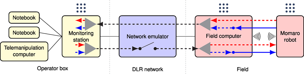
Figure 10. Communication architecture. Components in the vicinity of the operators are shown in yellow, DLR-provided components in blue, and components in the “arena”-network in red. Solid black lines represent physical network connections. Thick lines show the different channels, which stream data over the network (dotted: UDP, solid: TCP). The ROS logo  indicates a ROS master. UDP tunnel endpoints are designated by triangles. Streaming links (Section 9.1.2) are colored red, message links (Section 9.1.3) are shown in blue.
As the network emulator allows communication only through a single port per direction, we use the Linux tun interface to create a network tunnel over two ports. For UDP tunneling, we adapted code from the quicktun project.6 The tunnel wraps all packets in UDP packets, transmitted over the two designated ports. This allows us to use multiple communication channels without interference.
Separate ROS masters run on the robot, the field computer, and the ground station. Multiple operator computers can be connected to the ROS master running on the ground station to provide additional views and means for intervention.
9.1.1. Communication Software Module
Since our participation in the DLR SpaceBot Cup 2013 (Stückler et al., 2015), our group develops a robust software module (nimbro_network) for communication between multiple ROS masters over unreliable and high-latency networks. We used it with very good results in the DLR SpaceBot Cup 2013 and in the DARPA Robotics Challenge (Schwarz et al., 2016). Since the DRC, the module is now freely available7 under BSD-3 license. In contrast to custom-engineered network stacks for a particular purpose, it allows the generic transport of ROS topics and services. The module is ideally suited for situations where the connection drops and recovers unexpectedly, since it avoids any configuration/discovery handshake.
Several specific transports and compression methods exist, such as a ROS log transport, tf snapshotting, or H264 video stream compression.
For large messages, a transparent BZip2 compression can be enabled. Automatic rate limiting with configurable upper and lower bounds ensures that bandwidth limits are met.
nimbro_network also allows forward error correction (FEC), i.e., augmenting the sent packets with additional packets allowing content recovery from arbitrary subsets of sufficient size of transmitted packets. Depending on the message size, a Reed–Solomon codec (Lacan et al., 2009) or a LDPC-Staircase codec (Roca et al., 2008) is chosen.
Note that in principle ROS offers built-in network transparency. Since this functionality heavily relies on the TCP protocol for topic discovery and subscription, even when the “UDPROS” transport is chosen, this is unsuitable for unreliable and high-latency networks.
9.1.2. Streaming Data
Most high-bandwidth data from the robot are of streaming type. The key feature here is that lost messages do not lead to system failures, since new data will be immediately available, replacing the lost messages. In this particular application, it even would not make sense to repeat lost messages because of the high latencies involved. This includes
• video streams from the onboard cameras,
• transform information (TF),
• servo diagnostic information (e.g., temperatures),
• object detections, and
• other visualizations.
In the uplink direction, i.e., commands from the operator crew to the robot, this includes, e.g., direct joystick commands.
Consequently, we use the nimbro_network UDP transport for streaming data (red in Figure 10). The transport link between robot and field computer uses the FEC capability of nimbro_network with 25% additional recovery packets to compensate WiFi packet loss without introducing new latency.
9.1.3. Message Data
Other data are of the message type, including
• Laser pointclouds,
• SLAM maps,
• SLAM transforms,
• ROS action status messages, and
• ROS service calls.
Here, a message loss might be costly (e.g., SLAM maps are only generated on every scanner rotation) or might even lead to system failure (e.g., loss of a ROS action state transition). Therefore, the TCP transport is used for this kind of messages over the WiFi link to eliminate the possibility of packet loss. The link over the network emulator is still implemented with the UDP protocol, since there is no packet loss here and the high latencies prohibit TCP handshakes. The message links are colored blue in Figure 10.
10. Mission Control Interfaces
For the operator crew, situational awareness is most important. Our system shows camera images, 3D visualization, and diagnosis information on a central ground station with four monitors (see Figure 11).
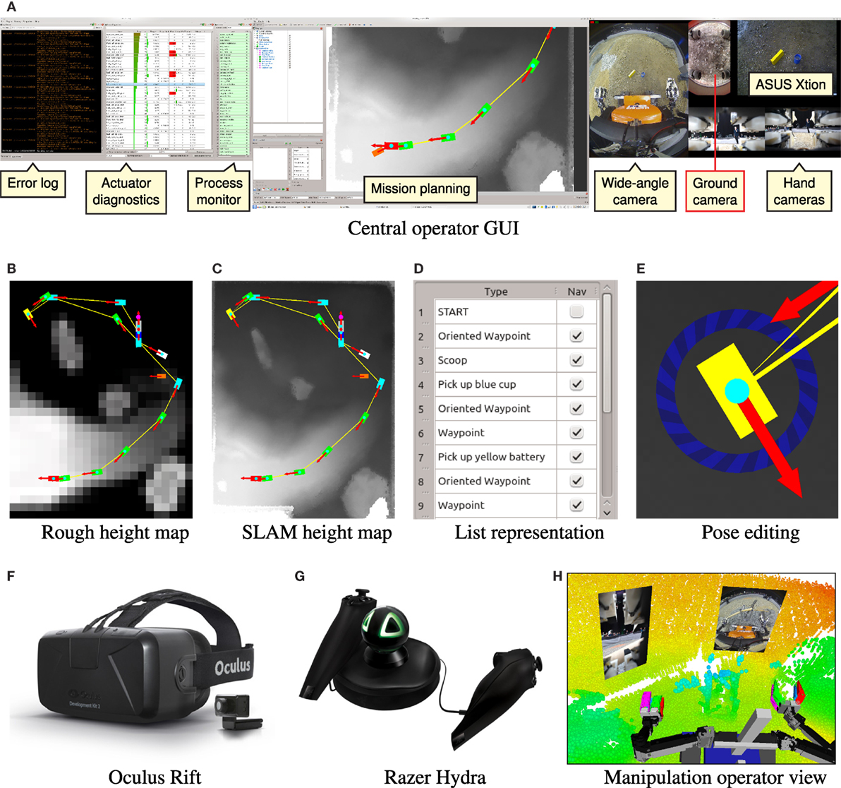
Figure 11. Operator interfaces. (A) Overview of the GUI shown on the three lower screens of the main ground station. The left, center, and right screens are dedicated to system monitoring and diagnosis, mission planning, and camera images, respectively. (B) Mission plan on rough height map provided by DLR. (C) Mission plan on detailed height map generated from the SLAM map. (D) List representation of the first 8 poses. The “Nav” column can be used to disable navigation (e.g., start grasping an object immediately). (E) Pose editing using interactive marker controls. The position can be modified by dragging the rectangle. The pose is rotated by dragging on the blue circle. Teleoperation interfaces: operator uses (F), oculus rift DK2 HMD, and (G) Razer Hydra 6 DOF controllers for immersive teleoperation. (H) 3rd person view of the scene rendered in the Oculus HMD during debris cleaning (see Figure 13).
In order to cope with the degraded communication link, the system needs to be as autonomous as possible, while retaining the ability to interrupt, reconfigure, or replace autonomous behavior by manual intervention. To this end, our system provides three levels of control to the operator crew. On the highest level, entire missions can be specified and executed. The intermediate level allows configuration and triggering of individual autonomous behaviors, such as grasping an object. On the lowest level, the operators can directly control the base velocity using a joystick or move individual DOF of the robot.
The last aspect of our control paradigm is remote debugging. Operators need to be able to directly introspect, debug, and manipulate the software on the robot in order to prevent relatively simple problems from escalating to mission failures.
We describe the developed operator interfaces in the following.
10.1. Mission Planning and Execution
Our mission control layer is able to execute all required tasks in the SpaceBot Camp specification. The mission can be specified fully in advance on a rough height map and can later be interactively refined as the mission progresses, and a more detailed map of the environment is created.
A specified mission consists of a list of 2D poses in the height map frame. Attached to each pose is an optional action, which is executed when the robot reaches the pose. Poses without an associated action are just used as navigation targets. Supported actions include:
• Taking a soil sample using the scoop in one hand,
• approaching and grasping the battery,
• approaching the cup, filling it with the soil sample and grasping it, and
• approaching the base station and performing all station manipulation tasks.
The mission can be configured and monitored using our Mission GUI (see Figure 11). During the mission, execution can be stopped at any time, mission updates can be performed, and the execution resumed. Missions can also be spliced in the sense that the currently performed action is carried out and then execution switches to a new mission.
In the case of a failure of the mission control level, or if the operator judges that the system will not be able to carry out the mission autonomously, the execution can be interrupted and the task in question can be carried out using the lower control levels. Afterward, the mission can be resumed starting after the completed task.
10.2. Semiautonomous Control
The semiautonomous control level gives direct access to all individual, less autonomous behaviors. This includes
• approaching an object,
• grasping an object,
• performing single manipulation tasks, and
• navigating to a goal pose.
10.3. Low-Level Control
If all autonomous behaviors fail, the operators can also directly teleoperate the robot. For manipulation, our operators can choose between on-screen teleoperation using 6D interactive markers in either Cartesian or joint space or immersive 3D telemanipulation (see Figure 11) using an Oculus Rift HMD and 6D magnetic trackers [see Rodehutskors et al. (2015) for details].
For navigation, the operator can use a joystick to directly control the base velocity. Teleoperation speed is of course limited by the high feedback latency, so that this method is only used if the navigation planners get stuck. Finally, several macros can be used to influence the robot posture or recover from servo failures such as overheating.
10.4. Remote Introspection and Debugging
To be able to react to software problems or mechanical failures, operators first need to be aware of the problem. Our system addresses this concern by
• providing direct access to the remote ROS log,
• showing the state of all ROS processes, and
• transmitting and displaying 3D visualization data from the autonomous behaviors.
Once aware of the problem, the operators can interact with the system through ROS service calls over our nimbro_network solution, parameter changes, or ROS node restarts through rosmon. In extreme cases, it is even possible to push small Git code patches over the network and trigger re-compilation on the robot. If everything else fails, the operators can access a remote command shell on the robot using the mosh shell (Winstein and Balakrishnan, 2012), which is specifically optimized for high-latency, low-bandwidth situations. The shell gives full access to the underlying Linux operating system.
11. Evaluation
Momaro has been evaluated in several simulations and lab experiments as well as in the DARPA Robotics Challenge (DRC) Finals in June 2015, during the DLR SpaceBot Cup Qualification in September 2015, and the DLR SpaceBot Camp in November 2015 (Kaupisch et al., 2015). For details on our performance at the DRC Finals, we refer to Schwarz et al. (2016). Here, we will focus on our performance at the SpaceBot Qualification and Camp.
In preparation for the DLR SpaceBot finals, the SpaceBot Cup Qualification tested basic capabilities of the robotic system. To qualify, participants had to solve three tasks which involved exploration and mapping of an arena and manipulation of the cup and the battery, but no assembly. In contrast to the finals, the communication uplink time was unlimited, which lowered the required autonomy level. Using our intuitive telemanipulation approaches, our team was the only team to successfully qualify in the first attempt. Further information about our performance is available on our website.8 Since only two other teams managed to qualify using their second attempt, the planned SpaceBot Cup competition was changed to an open demonstration, called the SpaceBot Camp.
The SpaceBot Camp required participants to solve mapping, locomotion, and manipulation tasks in rough terrain. As detailed in Section 1, the battery and cup (with soil sample) had to be found and transported to the base station object, where an assembly task was to be performed. The participants were provided with a coarse map of the environment that had to be refined by the robot’s mapping system. As detailed in Section 9, the communication link to the operator crew was severely constrained both in latency (2 s per direction) and in availability.
11.1. Locomotion
While Momaro was mainly evaluated on asphalt at the DRC (Schwarz et al., 2016), the SpaceBot Camp arena included various types of soil and stones (see Figure 14). We did not experience any problems on the main traversable area, which was covered with flattened soil mixed with stones. During our run, we avoided the gravel and sand areas. We also traversed the soil sample area (loose granulate), and parts of the slopes covered with gravel, as long as the inclination permitted. Testing after our run confirmed that Momaro’s wheels were not suited for the fine sand areas on the edge of the ramp, causing the robot to get stuck.
While preparing for the SpaceBot Camp, we learned that our pitch stabilization control method works reliably, even under extreme conditions. Being able to reliably overcome ramps with inclines greater than 20°, we were confident that locomotion would not pose a problem during the competition. Unfortunately, we only employ stabilization in pitch direction. Turning around the yaw axis on a pitched slope can result in a dangerous roll angle. We dealt with this issue during our final run by placing enough waypoints on the primary slope in the course to ensure proper orientation (see Figure 11).
11.2. Mapping and Self-Localization
Our mapping system continuously built an allocentric map of the environment during navigation, guided by waypoints specified on the coarse height map. The coarse map and the allocentric map, generated from our mapping system, are shown in Figure 12. While showing the same structure as the coarse map, the resulting allocentric map is accurate and precisely models the environment. During a mission, the map is used for localization and to assess traversability for navigation. The estimated localization poses are shown in Figure 14.
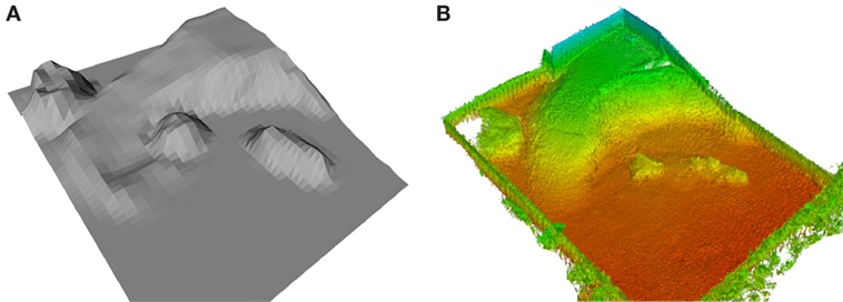
Figure 12. Map refinement. (A) Rough map of the SpaceBot Camp 2015 arena. (B) The resulting global map from data acquired during the competition.
Despite the challenging planetary-like environment, causing slip in odometry and vibrations of robot and sensor, our mapping system showed very robust and reliable performance. There was only one situation during the run where the operators had to intervene: due to traversing the abandoned scoop tool – used to take the soil sample – the robot was exposed to a fast and large motion, resulting in a distorted 3D scan. This distorted 3D scan caused spurious measurements in the map. The operators decided to clear the SLAM map using a remote service call to prevent localization failures. The map was rebuilt from this point on and successfully used for the rest of the mission.
11.3. Object Manipulation
While preparing our run, we found the battery slot in the base station to have a significant resistance due to a build-in clamping mechanism. Due to our flexible motion design workflow, we were able to alter the motion, so that Momaro would execute small up- and downward motions while pushing to find the best angle to overcome the resistance.
The insertion of the battery requires high precision. To account for inaccuracies in both battery and station pose, we temporarily place the battery on top of the station. After grasping the battery again, we can be sure that any offset in height is compensated.
Furthermore, we found it to be error prone to grasp the battery at the very end, which is necessary to entirely push it inside the slot. Instead, we push the battery in as far as possible until the hand touches the base station. After releasing the battery, we position the closed hand behind it and push it completely inside with part of the wrist and proximal finger segments.
Overall, our straightforward keyframe adaption approach proved itself to be very useful. Compared to motion–planning techniques, it lacks collision avoidance and full trajectory optimization, but it is sufficient for the variety of performed tasks.
11.4. Full System Performance at DLR SpaceBot Camp 2015
After a restart caused by a failed actuator (described below), Momaro solved all tasks of the SpaceBot Camp with supervised autonomy. Our team was the only one to demonstrate all tasks including the optional soil sample extraction. Figure 14 gives an overview of the sequence of performed tasks. A video of our performance can be found online.9 While overall the mission was successful, we experienced a number of problems which will be discussed in detail.
In our run, Momaro failed to take the soil sample in the first attempt. During the vigorous scooping motion, the scoop turned inside the hand (cf. Figures 2 and 13). We found the problem to be a malfunctioning finger actuator in the hand holding the scoop. Since we were confident that Momaro would be able to solve all tasks even in the remaining 50:20 min, we restarted the whole run after performing a software reset on the affected finger and letting it cool down.
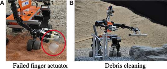
Figure 13. Details of our run at SpaceBot camp. (A) Due to a failed finger actuator, Momaro failed to take the soil sample in the first attempt. (B) After finishing all tasks of the SpaceBot Camp, we showed Momaro’s universal capabilities by removing debris from the terrain under teleoperation.
In the second attempt, scooping succeeded and Momaro was able to complete all remaining tasks as well. See Figure 14 for detailed images of the subtasks. Timings of the run are listed in Table 1.
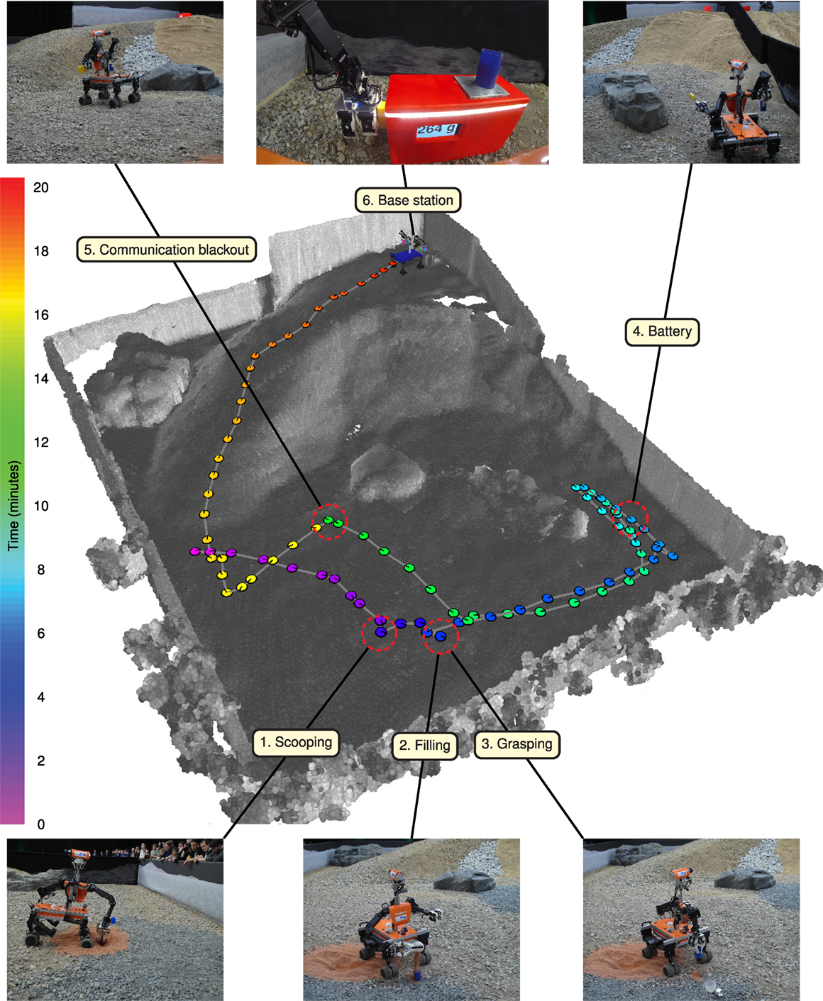
Figure 14. Overview of the executed mission at SpaceBot Camp. The mission starts by scooping the soil sample, filling it into the cup and grasping the cup, then locating and grasping the battery pack. After waiting until the end of scheduled communication blackout, the mission is concluded by Base station assembly.
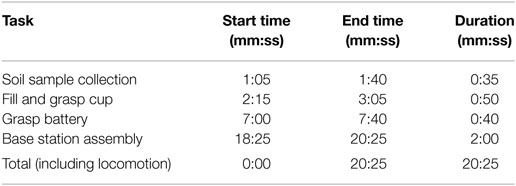
Table 1. Timings of our run at the DLR SpaceBot Camp 2015.
Although Momaro was able to complete all tasks, this was not possible fully autonomously. While approaching the battery, a timeout aborted the process. This built-in safety feature made operator interaction necessary to resume the approach. Without intervention, Momaro would have executed the remainder of the mission without the battery object.
As Momaro reached the main slope of the course, we also approached the time of the first communication blackout, because we lost time in the beginning due to the restart. The operator crew decided to stop Momaro at this point, as we knew that going up would be risky and intervention would have been impossible during the blackout. After the blackout, autonomous operation resumed and Momaro successfully went up the ramp to perform the assembly tasks at the base station (Figure 14). Although the operators paused autonomous navigation at one point on the slope to assess the situation, no intervention was necessary and navigation resumed immediately.
After finishing the course in 20:25 min, we used the remaining time to show some of Momaro’s advanced manipulation capabilities by removing debris from the terrain with Momaro and our intuitive teleoperation interface (Figure 13).
12. Lessons Learned
Our successful participation in the SpaceBot Camp was an extremely valuable experience, identifying strong and weak points of our system in a competitive benchmark within the German robotics community. Lessons learned include
• Mechanical Design. While the humanoid torso raised the center of gravity and thus caused stability concerns on high terrain inclines, it allowed us to perform bimanual manipulation. Being able to carry both objects in the hands allowed us to omit storing the objects in separate holders on the robot, saving time. Furthermore, our end effector design allowed us to use a scoop to take the soil sample. The soil extraction task was not attempted by any other team. In future work, we will further improve the robot balance control to operate in more difficult rough terrain. For instance, adaptive roll stabilization could advance Momaro’s locomotion capabilities.
• Actuator Monitoring. Our system provides extensive diagnostic actuator feedback such as temperature and current consumption. Still, this was not enough to prevent the failure of the finger actuator during our run. Actuator monitoring and damage prevention should have a high priority during development.
• Software Design: Autonomy Follows Teleoperation. Our unique history of competing previously in the DARPA Robotics Challenge, a competition heavily focused on intuitive teleoperation, set us apart from other teams. In particular, resulting from the DRC competition, we had extensive intuitive teleoperation abilities before starting work on the higher autonomy required by the SpaceBot Camp. We suspect that most other teams followed the opposite approach, augmenting the autonomy later on with teleoperation facilities, which can be difficult if the system was not designed for teleoperation from the start. Treating the autonomy as an additional layer on a teleoperable system ensures that the operator crew has full control of the system at all time. Furthermore, this also accelerates development, since missing autonomous functionalities can be substituted by intuitive teleoperation. We demonstrated the ability of our telemanipulation solution after our run by removing debris and thus clearing the robot’s path.
• Intelligent Progress Monitoring. Our mission control layer included some very basic error handling, e.g., fixed timeouts on certain actions. Unfortunately, one of these timeouts resulted in an early abort of the battery approach in our run, which had to be corrected by operator action. A more intelligent system, tracking the progress of the current task, would have noticed that the approach was still progressing and would have continued the approach. In future, we will investigate such resilient progress monitoring methods in more detail.
13. Conclusion
In this article, we presented the mobile manipulation robot Momaro and its ground station. We provided details on the software and hardware architecture of the integrated robot system and motivate design choices. The feasibility, flexibility, usefulness, and robustness of our design were evaluated with great success at the DLR SpaceBot Camp 2015.
Novelties include an autonomous hybrid mobile base combining wheeled locomotion with active stabilization in combination with fully autonomous object perception and manipulation in rough terrain. For situational awareness, Momaro is equipped with a multitude of sensors such as a continuously rotating 3D laser scanner, IMU, RGB-D camera, and a total of seven color cameras. Although our system was build with comprehensive autonomy in mind, all aspects from direct control to mission specification can be teleoperated through intuitive operator interfaces. Developed for the constraints posed by the SpaceBot Camp, our system also copes well with degraded network communication between the robot and the monitoring station.
The robot localizes by fusing wheel odometry and IMU measurements with pose observations obtained in a SLAM approach using laser scanner data. Autonomous navigation in rough terrain is tackled by planning cost-optimal paths in a 2D map of the environment. High-level autonomous missions are specified as augmented waypoints on the 2.5D height map generated from SLAM data. For object manipulation, the robot detects objects with its RGB-D camera and executes grasps using parametrized motion primitives.
In the future, shared autonomy could be improved by automatic failure detection, such that the robot reports failures and recommends a suitable semiautonomous control mode for recovery. Currently, only vision-based manipulation is supported by the system. Additional touch and force-torque sensing could potentially lead to more robust manipulation capabilities.
Author Contributions
MSchwarz was the team leader and main author. MB contributed in pose estimation and evaluation. DD developed the SLAM system. SS developed the motion adaption system. AP contributed the autonomous navigation planner. CL developed operator interfaces and designed motions. MSchreiber constructed the robot and provided mechanical design details. SB initiated and managed the project, mentored the team during the preparations and competition, and assisted in writing this article.
Conflict of Interest Statement
The authors declare that the research was conducted in the absence of any commercial or financial relationships that could be construed as a potential conflict of interest.
Funding
This work was supported by the European Union’s Horizon 2020 Programme under Grant Agreement 644839 (CENTAURO) and by Deutsches Zentrum für Luft- und Raumfahrt e.V. (DLR) under Grant No. SORA1413.
Footnotes
- ^http://www.dlr.de/rd/desktopdefault.aspx/tabid-8101/
- ^http://ais.uni-bonn.de/research.html
- ^http://wiki.ros.org/navfn
- ^http://wiki.ros.org/dwa_local_planner
- ^http://moveit.ros.org
- ^http://wiki.ucis.nl/QuickTun
- ^http://github.com/AIS-Bonn/nimbro_network
- ^http://www.ais.uni-bonn.de/nimbro/Explorer
- ^https://youtu.be/q_p5ZO-BKWM
References
Adachi, H., Koyachi, N., Arai, T., Shimiza, A., and Nogami, Y. (1999). “Mechanism and control of a leg-wheel hybrid mobile robot,” in Proc. of the IEEE/RSJ Int. Conference on Intelligent Robots and Systems (IROS), Vol. 3 (Kyongju: IEEE), 1792–1797.
Borst, C., Wimbock, T., Schmidt, F., Fuchs, M., Brunner, B., Zacharias, F., et al. (2009). “Rollin’ Justin – mobile platform with variable base,” in Proc. of the IEEE Int. Conference on Robotics and Automation (ICRA) (Kobe: IEEE), 1597–1598.
Buss, S. R., and Kim, J.-S. (2005). Selectively damped least squares for inverse kinematics. Graph. GPU Game Tools 10, 37–49. doi:10.1080/2151237X.2005.10129202
Cheng, G., and Zelinsky, A. (2001). Supervised autonomy: a framework for human-robot systems development. Auton. Robots 10, 251–266. doi:10.1023/A:1011231725361
Cho, B.-K., Kim, J.-H., and Oh, J.-H. (2011). Online balance controllers for a hopping and running humanoid robot. Adv. Robot. 25, 1209–1225. doi:10.1163/016918611X574687
Droeschel, D., Stückler, J., and Behnke, S. (2014a). “Local multi-resolution representation for 6d motion estimation and mapping with a continuously rotating 3d laser scanner,” in Proc. of the IEEE Int. Conference on Robotics and Automation (ICRA) (Hong Kong: IEEE), 5221–5226.
Droeschel, D., Stückler, J., and Behnke, S. (2014b). “Local multi-resolution surfel grids for mav motion estimation and 3d mapping,” in Proc. of the Int. Conference on Intelligent Autonomous Systems (IAS), Padova.
Endo, G., and Hirose, S. (2000). “Study on roller-walker (multi-mode steering control and self-contained locomotion),” in Proc. of the IEEE Int. Conference on Robotics and Automation (ICRA), Vol. 3 (San Francisco: IEEE), 2808–2814.
Fox, D., Burgard, W., and Thrun, S. (1997). The dynamic window approach to collision avoidance. IEEE Robot. Autom. Mag. 4, 23–33. doi:10.1109/100.580977
Gillett, R., Greenspan, M., Hartman, L., Dupuis, E., and Terzopoulos, D. (2001). “Remote operation with supervised autonomy (ROSA),” in Proceedings of the 6th International Conference on Artificial Intelligence, Robotics and Automation in Space (i-SAIRAS 2001), Montreal.
Halme, A., Leppänen, I., Suomela, J., Ylönen, S., and Kettunen, I. (2003). WorkPartner: interactive human-like service robot for outdoor applications. Int. J. Robot. Res. 22, 627–640. doi:10.1177/02783649030227011
Hebert, P., Bajracharya, M., Ma, J., Hudson, N., Aydemir, A., Reid, J., et al. (2015). Mobile manipulation and mobility as manipulation – design and algorithms of robosimian. J. Field Robot. 32, 255–274. doi:10.1002/rob.21566
Heppner, G., Roennau, A., Oberländer, J., Klemm, S., and Dillmann, R. (2015). Laurope – Six Legged Walking Robot for Planetary Exploration Participating in the SpaceBot Cup, Noordwijk: ESA.
Holz, D., Holzer, S., Rusu, R. B., and Behnke, S. (2011). “Real-time plane segmentation using RGB-D cameras,” in RoboCup 2011: Robot Soccer World Cup XV (Istanbul: Springer), 306–317.
Hornung, A., Wurm, K. M., Bennewitz, M., Stachniss, C., and Burgard, W. (2013). OctoMap: an efficient probabilistic 3D mapping framework based on octrees. Auton. Robots 34, 189–206. doi:10.1007/s10514-012-9321-0
Huang, T., Yang, G., and Tang, G. (1979). A fast two-dimensional median filtering algorithm. IEEE Trans. Acoust. Speech Signal Process. 27, 13–18. doi:10.1109/TASSP.1979.1163188
Johnson, M., Shrewsbury, B., Bertrand, S., Wu, T., Duran, D., Floyd, M., et al. (2015). Team IHMC’s lessons learned from the DARPA robotics challenge trials. J. Field Robot. 32, 192–208. doi:10.1002/rob.21571
Joyeux, S., Schwendner, J., and Roehr, T. M. (2014). “Modular software for an autonomous space rover,” in Proceedings of the 12th International Symposium on Artificial Intelligence, Robotics and Automation in Space (SAIRAS), Montreal.
Kaupisch, T., and Fleischmann, M. (2015). “Mind the robot – rovers leave tracks in the artificial planetary sands,” in COUNTDOWN – Topics from the DLR Space Administration, Vol. 31, 38–43. Available at: http://www.dlr.de/rd/en/desktopdefault.aspx/tabid-4788/7944_read-45190/
Kaupisch, T., Noelke, D., and Arghir, A. (2015). “DLR spacebot cup – Germany’s space robotics competition,” in Proc. of the Symposium on Advanced Space Technologies in Robotics and Automation (ASTRA), Noordwijk.
Kim, M.-S., and Oh, J.-H. (2010). Posture control of a humanoid robot with a compliant ankle joint. Int. J. HR 07, 5–29. doi:10.1142/S0219843610001988
Kröger, T. (2011). “Opening the door to new sensor-based robot applications – the reflexxes motion libraries,” in Proc. of the IEEE Int. Conference on Robotics and Automation (ICRA), Shanghai.
Kuemmerle, R., Grisetti, G., Strasdat, H., Konolige, K., and Burgard, W. (2011). “G2o: a general framework for graph optimization,” in Proc. of the IEEE Int. Conference on Robotics and Automation (ICRA).
Lacan, J., Roca, V., Peltotalo, J., and Peltotalo, S. (2009). Reed-Solomon Forward Error Correction (FEC) Schemes. Technical Report RFC (5510). IETF.
Mehling, J., Strawser, P., Bridgwater, L., Verdeyen, W., and Rovekamp, R. (2007). “Centaur: NASA’s mobile humanoid designed for field work,” in Proc. of the IEEE Int. Conference on Robotics and Automation (ICRA) (Roma: IEEE), 2928–2933.
Pedersen, L., Kortenkamp, D., Wettergreen, D., and Nourbakhsh, I. (2003). “A survey of space robotics,” in Proceedings of the 7th International Symposium on Artificial Intelligence, Robotics and Automation in Space (NASA), 19–23.
Quigley, M., Conley, K., Gerkey, B., Faust, J., Foote, T., Leibs, J., et al. (2009). “Ros: an open-source robot operating system,” in ICRA Workshop on Open Source Software, Vol. 3, (Kobe), 5.
Raibert, M., Blankespoor, K., Nelson, G., Playter, R., The Big-Dog Team. (2008). “BigDog, the rough-terrain quadruped robot,” in Proceedings of the 17th World Congress, The International Federation of Automatic Control (Seoul, Korea: Elsevier), 10823–10825.
Roca, V., Neumann, C., and Furodet, D. (2008). Low Density Parity Check (LDPC) Staircase and Triangle Forward Error Correction (FEC) Schemes. RFC (5170). IETF.
Rodehutskors, T., Schwarz, M., and Behnke, S. (2015). “Intuitive bimanual telemanipulation under communication restrictions by immersive 3d visualization and motion tracking,” in Proc. of the IEEE-RAS Int. Conference on Humanoid Robots (Humanoids), Seoul.
Roennau, A., Kerscher, T., and Dillmann, R. (2010). “Design and kinematics of a biologically-inspired leg for a six-legged walking machine,” in 3rd IEEE RAS and EMBS International Conference on Biomedical Robotics and Biomechatronics (BioRob) (Tokyo: IEEE), 626–631.
Schwarz, M., and Behnke, S. (2014). “Local navigation in rough terrain using omnidirectional height,” in Proc. of the German Conference on Robotics (ROBOTIK) (Munich: VDE).
Schwarz, M., Rodehutskors, T., Droeschel, D., Beul, M., Schreiber, M., Araslanov, N., et al. (2016). NimbRo rescue: solving disaster-response tasks through mobile manipulation robot Momaro. J. Field Robot. Available at: http://www.ais.uni-bonn.de/papers/JFR_NimbRo_Rescue_Momaro.pdf
Schwendner, J., Roehr, T. M., Haase, S., Wirkus, M., Manz, M., Arnold, S., et al. (2014). “The artemis rover as an example for model based engineering in space robotics,” in ICRA Workshop on Modelling, Estimation, Perception and Control of All Terrain Mobile Robots, Hong Kong.
Segal, A., Haehnel, D., and Thrun, S. (2009). “Generalized-ICP,” in Proc. of Robotics: Science and Systems, Seattle.
Semini, C., Tsagarakis, N., Guglielmino, E., Focchi, M., Cannella, F., and Caldwell, D. (2011). Design of HyQ-A hydraulically and electrically actuated quadruped robot. Proc. Inst. Mech. Eng. I J. Syst. Control Eng. 225, 831–849. doi:10.1177/0959651811402275
Stentz, A., Herman, H., Kelly, A., Meyhofer, E., Haynes, G. C., Stager, D., et al. (2015). CHIMP, the CMU highly intelligent mobile platform. J. Field Robot. 32, 209–228. doi:10.1002/rob.21569
Stückler, J., Schwarz, M., Schadler, M., Topalidou-Kyniazopoulou, A., and Behnke, S. (2015). NimbRo Explorer: semiautonomous exploration and mobile manipulation in rough terrain. J. Field Robot. 33, 411–430. doi:10.1002/rob.21592
Sünderhauf, N., Neubert, P., Truschzinski, M., Wunschel, D., Pöschmann, J., Lange, S., et al. (2014). “Phobos and deimos on mars – two autonomous robots for the dlr spacebot cup,” in Proceedings of the 12th International Symposium on Artificial Intelligence, Robotics and Automation in Space-i-SAIRAS’14 (Montreal: The Canadian Space Agency (CSA-ASC)).
Wedler, A., Rebele, B., Reill, J., Suppa, M., Hirschmüller, H., Brand, C., et al. (2015). “LRU – lightweight rover unit,” in Proc. of the 13th Symposium on Advanced Space Technologies in Robotics and Automation (ASTRA), Noordwijk.
Keywords: mapping, mobile manipulation, navigation, perception for grasping and manipulation, space robotics and automation
Citation: Schwarz M, Beul M, Droeschel D, Schüller S, Periyasamy AS, Lenz C, Schreiber M and Behnke S (2016) Supervised Autonomy for Exploration and Mobile Manipulation in Rough Terrain with a Centaur-Like Robot. Front. Robot. AI 3:57. doi: 10.3389/frobt.2016.00057
Received: 21 January 2016; Accepted: 16 September 2016;
Published: 13 October 2016
Edited by:
Fumio Kanehiro, National Institute of Advanced Industrial Science and Technology, JapanReviewed by:
John Nassour, Chemnitz University of Technology, GermanyMaja Borry Zorjan, Université de Versailles Saint-Quentin-en-Yvelines, France
Giuseppe Quaglia, Polytechnic University of Turin, Italy
Copyright: © 2016 Schwarz, Beul, Droeschel, Schüller, Periyasamy, Lenz, Schreiber and Behnke. This is an open-access article distributed under the terms of the Creative Commons Attribution License (CC BY). The use, distribution or reproduction in other forums is permitted, provided the original author(s) or licensor are credited and that the original publication in this journal is cited, in accordance with accepted academic practice. No use, distribution or reproduction is permitted which does not comply with these terms.
*Correspondence: Max Schwarz, max.schwarz@uni-bonn.de