Department of Biological Sciences, Howard Hughes Medical Institute, Columbia University, New York, NY, USA
Two-photon imaging has become a useful tool for optical monitoring of neural circuits, but it requires high laser power and serial scanning of each pixel in a sample. This results in slow imaging rates, limiting the measurements of fast signals such as neuronal activity. To improve the speed and signal-to-noise ratio of two-photon imaging, we introduce a simple modification of a two-photon microscope, using a diffractive optical element (DOE) which splits the laser beam into several beamlets that can simultaneously scan the sample. We demonstrate the advantages of DOE scanning by enhancing the speed and sensitivity of two-photon calcium imaging of action potentials in neurons from neocortical brain slices. DOE scanning can easily improve the detection of time-varying signals in two-photon and other non-linear microscopic techniques.
Two-photon microscopy (Denk et al., 1990
) has become an important tool for the functional study of neural circuits, due to its ability to deliver localized excitation in highly scattering media, such as living brain tissue (Denk, 1994
; Denk et al., 1994
). For example, using two-photon calcium imaging, one can monitor the activity of individual synapses (Yuste and Denk, 1995
) or neuronal populations (Cossart et al., 2003
), whereas with two-photon uncaging of neurotransmitters, one can activate or inactivate neurons, or parts of a neuron, at will (Denk et al., 1994
; Matsuzaki et al., 2001
; Nikolenko et al., 2007
).
One problem with two-photon microscopy is that laser scanning of a sample is normally performed in a sequential fashion, because high light intensities are necessary to generate two-photon excitation (Denk et al., 1990
). This slows image acquisition, since each pixel needs to be scanned before an image is assembled. One solution to this problem is to selectively scan only pixels of interest. This can be achieved with random access scanning, in which those pixels are serially illuminated (Iyer et al., 2006
; Otsu et al., 2008
; Reddy and Saggau, 2005
; Reddy et al., 2008
), or with a spatial light modulator (SLM), which splits the beam into any arbitrary pattern, allowing the simultaneous illumination or photostimulation of selected pixels (Lutz et al., 2008
; Nikolenko et al., 2008
).
As another solution to enhance the speed of image acquisition, one can split the laser beam into a series of beamlets, which can then scan the sample simultaneously, thereby imaging the entire field of view in less time (Bewersdorf et al., 1998
; Buist and Brakenhoff, 1998
; Kurtz et al., 2006
; Nielsen et al., 2001
). This takes advantage of the fact that many mode-locked lasers provide more output power than can be used with any single beam without inducing tissue damage. Multiplexing beams in such a way can be achieved by the use of a system of mirrors, although such systems are complicated to align and interface with existing microscopes, and are also quite costly (Kurtz et al., 2006
; Nielsen et al., 2001
). As an alternative to beam-splitting mirrors, one can use a diffractive optical element (DOE), an optical device that multiplexes a laser beam into a series of fixed beamlets. DOEs are simple and inexpensive and DOE scanning can be easily implemented in pre-existing microscopes. Indeed, DOEs beam splitters have been used to increase the efficacy of two-photon uncaging of glutamate, and thus generate depolarizations that are reliable enough to fire neurons (Nikolenko et al., 2007
). We now describe the use of DOE scanning to enhance two-photon imaging in neuroscience applications, expanding and further developing the earlier work of Sacconi et al. (2003
). We first present a strategy to improve the signal-to-noise (S/N) ratio of two-photon fluorescence measurements by horizontally scanning multiple beamlets across a sample. Secondly, to increase the speed of image acquisition, we position the DOE beamlets vertically, with each beamlet simultaneously scanning a subregion of the field of view. As we show, these two different DOE scanning regimes can significantly improve the two-photon detection of action potentials in neuronal populations.
Optical Design
We used a custom made two-photon microscope (Nikolenko et al., 2003
) that employs galvanometer scanners and image acquisition software from a commercial confocal microscope (Fluoview 200; Olympus, Center Valley, PA, USA). A Ti: Sapphire ultrafast mode-locked laser (Chameleon Ultra, Coherent, Santa Clara, CA, USA) (Figure 1
B, element 1), was tuned to 785 nm, providing approximately 2.8 W of average power. A pockels cell (Model 350-160, Conoptics Inc, Danbury, CT, USA) (Figure 1
B, element 2) was used to modulate the total available laser power in the light path.
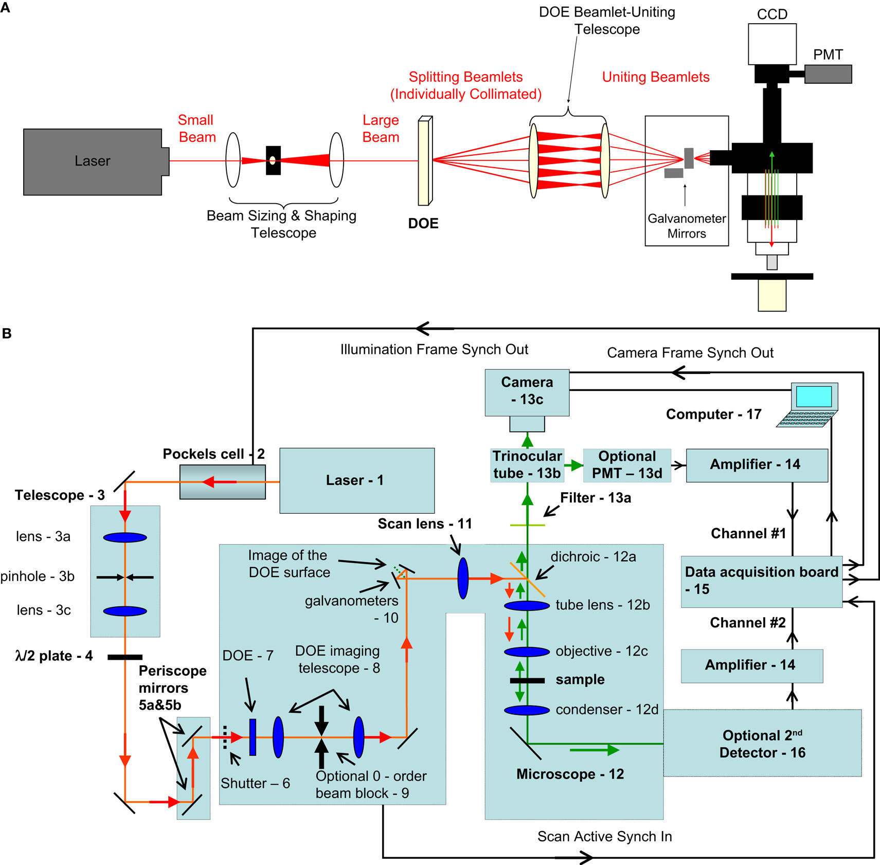
Figure 1. Optical path and microscope design. (A) Conceptual schematic demonstrating beam splitting using a diffractive optical element (DOE). These beams are brought together onto the galvanometer mirrors which may scan and which transmit beams for exciting the sample underneath the objective. While the telescope does not change the collimation of the individual beamlets, it does change the size of the outgoing beamlets and so a pre-sizing telescope is used before the DOE-telescope complex (at left). Image collection can be performed using either a photomultiplier tube (PMT) or a CCD camera. (B) Detailed diagram of all elements of our optical and image acquisition setup
- Titanium sapphire femtosecond source laser (Chameleon Ultra, Coherent Inc., Santa Clara, CA, USA)
- Pockels cell is controlled by voltage input and regulates excitation laser intensity – in our case works essentially as a fast “shutter”. (Pockels cell: Model 350-160, Conoptics Inc., Danbury, CT, USA)
- Beam-sizing telescope (in combination with 8 it provides the beam of convenient size at the input port of the microscope – to properly fill the back aperture of the microscope objective). This is composed of lenses (model BK7 with anti-reflection coating permitting near IR), holders and cage frames from Thorlabs (Newton, NJ, USA)
- An optional half-wave plate (depending on type of DOE used, it could be employed for changing diffraction efficiency and making intensity of zero diffraction order beamlet equal to other beamlets). Thorlabs HWP05M-950 achromatic λ/2 plate, 690–1200 nm.
- Periscope – mirrors to deliver laser beam to the input port of an upright microscope
- Slow mechanical safety shutter (part of original Fluoview 200 system Olympus America Inc, Center Valley, PA, USA)
- DOE [11 beamlets SLH-511D-1.5-(785) or 5 beamlets SLH-505X-(0.23)-(780) from StockerYale, Dollard-Des-Ormeaux, QC, Canada]
- DOE imaging telescope relays the image of the DOE surface to approximately the plane of scanning mirrors (Thorlabs including 1 inch diameter initial lens and 2 inch diameter second lens).
For 11-beamlet DOE we used first lens with focal distance F1 = 75 mm, and the second lens has focal distance F2 = 125 mm; distance between the DOE and the first lens is 70 mm to image the surface of DOE to the plane between galvanometer mirrors (and subsequently onto the plane of the back aperture of the microscope objective).
For 5-beamlet DOE we used first F1 = 100 mm, and F2 = 500 mm; distance between the DOE and the first lens is 60 mm. We were modifying the magnification of this relay telescope in order to achieve desired physical beamlet separation on the sample plane according to used magnification of the microscope objective. For purposes of convenience five-beamlet DOE and the relay telescope was actually placed on the optical table before the periscope mirrors. - An optional zero-order beam block (we used a thin metal rod for this purpose). This is often necessary in the case of DOEs that are designed to produce a pattern without a beamlet in the center location but which produce an unintended zero-order beamlet.
- 10. Scanning mirrors – original galvanometer scanners from the Fluoview 200 system controlled by native Olympus confocal software
- Scan (or “pupil-transfer”) lens – an original part of Fluoview laser scanning system (Olympus part number FVX-PL-IBX50/T).
- Upright microscope (Olympus BX50WI)
- Standard dichroic for two-photon fluorescence detection
- Tube lens – an essential part of the upright microscope
- Microscope objective
- Microscope bright field illumination condenser
- Detection system (detects shorter-wavelength light signified by green arrows)
- Band-pass filter to include only emission-wavelength light (Chroma, Rockingham, VT, USA)
- A standard microscope trinocular tube to switch between imaging ports: one of them is used for traditional whole-filed PMT detection, another – for fast imaging using the camera
- Cooled CCD camera (C9100-12, Hamamatsu, Bridgewater, NJ, USA)
- Optional PMT for traditional slow scanning imaging (Hamamatsu H7422-40P cooled GaAs)
- Current to voltage converters/signal amplifiers for PMT detection. (PE 5113 preamplifier Signal Recovery AMETEK Advanced Measurement Technology, Wokingham, UK.)
- Data acquisition unit – the part of original Fluoview 200 system
- Optional 2nd detector (Camera or PMT) for gathering optical signals in forward direction [two-photon excited fluorescence or second harmonics generation (SHG) signal)
- PC for data acquisition and equipment control.
DOE optics
We placed a DOE at a plane conjugated to the back aperture of the objective and the galvanometer mirrors (Figure 1
A). This element was followed in the optical path by a telescope, necessary to ensure that the beamlets emerging from the DOE were also joined back together at the galvanometer mirrors, allowing for each individual beamlet to remain collimated and for fine tuning the angle of -beamlet spread. When using DOEs with an even number of beamlets we eliminated the zero-order beamlet by mechanically blocking it. While each beamlet emerging from the DOE was of the same diameter as the laser beam incident on the DOE, the telescope which followed had the side-effect of changing the size of each beamlet by an amount proportional to the power of this telescope. For this reason we pre-shrink or pre-expand the incident laser with another telescope. Since our system already employs a telescope early in the light path to pass the beam through a pinhole (a spatial filter which ensures the circularity of the beam cross-sectional profile; Figure 1
B, element 3), we utilize this same telescope for pre-compensation size of the beam by simply changing the focal length and placement of the second lens of that telescope (Figure 1
A). This ensures that the beamlets slightly overfill the back aperture of our objective. The angle at which the beamlets impinge onto the galvanometer mirrors and are reflected from them determines the spatial spread of beamlets on the sample, a key variable in our experiments. This angle is controlled by the interbeam angle from the DOE (defined by its phase mask) and the power of the telescope between the DOE and the galvanometer mirrors.
Horizontal DOE scanning
For all experiments we used DOEs which created a series of evenly spaced beamlets over a single line. The DOE was easily rotated about the axis of the light path to create a line of points along any orientation. This rotation could be used to modulate the effective interbeamlet angular distance along the vertical dimension in fast scanning (see bellow and Movie in Supplementary Material). To increase the photon flux per pixel we used a five-beamlet DOE [SLH-505X-(0.23)-(780) from StockerYale] and positioned the beamlets horizontally to excite the same points, or points very nearby to each other (Figure 2
, top).
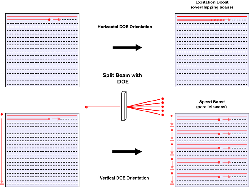
Figure 2. Two forms of DOE scanning. Schematic representations of strategies for utilizing a diffractive element to enhance two-photon imaging. Upper left: traditional raster scan imaging requires time for a mirror system to scan an excitation beam across a field of view and has only a certain ceiling quantity of excitation possible before photodamage occurs. Upper right: using a diffractive optical element (DOE) one can split our beam into an arbitrary number of beamlets. Using beamlets spread horizontally it is possible to image in a way that allows for summation of the signals excited by the sample at each pixel to yield greater signal and increased signal to noise ratio. Horizontal DOE mode or “excitation boost” may be used for either line scans or full-field frame scans (at the expense of some spatial resolution). Bottom: Vertical DOE mode or “speed boost” achieves greater speed of scanning than traditional raster scanning. By spacing DOE-created beamlets widely over the vertical aspect of the field of view and scanning each beamlet simultaneously horizontally across a narrow strip of the field of view it is possible to excite the full field of view in 1/(number of beamlets) the amount of time required for a single beam. As indicated by arrows at left of each representation of a field of view, in the standard raster scan mode, a single beam must make horizontal line scans along the entire height of the field (long arrow), whereas in speed boost, each beamlet simultaneously scans a fraction of the vertical aspect of the field (short arrows). This method requires a camera or any other similar wide-field light collection device (such as a photodiode array or multianode photomultiplier tube) with a resolution equal to at least the number of beamlets used, since more than one area is excited simultaneously.
In all experiments utilizing a DOE we ensured that each beamlet had sufficient power that it was capable of full fluorophore excitation. In experiments comparing single beam versus five beam imaging modes we left the DOE in place and generated five beamlets throughout both kinds of experiments with the only difference being that in the case of the single beam experiments we simply placed a simple iris diaphragm placed at intermediate imaging plane, as a barrier in the path of four beamlets, allowing only one to pass). Under these conditions, at 800 nm, the single central beam had a power of 24 mW on sample while the sum of the power of all five beams combined was 108 mW on sample, with average power for the other four beamlets being 21 mW and each individually within 5% of that average.
Galvanometer mirror scanning was performed identically to single-beam two-photon raster scan imaging and an amplified photomultiplier tube (PMT) was used for detection (PMT: H7422-P40 Hamamatsu, Bridgewater, NJ, USA; Amplifier: Signal Recovery AMETEK Advanced Measurement Technology, Wokingham, UK). The PMT collected emission light from all points simultaneously excited by the multiple beamlets from the DOE. The horizontal orientation of the beamlets was not strictly required for this excitation-boost regime. Rather it was a small spacing of the beamlets relative to the features of interest that is critical for this, however a horizontal orientation was the most straightforward such application. This imaging modality slightly reduces the spatial resolution of the imaging along the direction of beamlet orientation, but increases the integrated intensity of each imaged pixel over time, since each pixel was sampled multiple times, once by each beamlet. The horizontal or vertical orientation of the beamlets could be changed by rotating the DOE to maintain maximal resolution along a particular axis, while sacrificing resolution along the other axis to gain increased signal.
The width of separation between beamlets was controllable and determined the degree of loss of spatial resolution. This separation was determined by the angle of beamlets incident on the back aperture of the objective which in turn was determined by a combination of the angle of splitting between beamlets created by the DOE itself as well as the placement and power of any telescopes between that DOE and the imaging system itself. See Figure 1 in Supplementary Material for an example of imaging of 0.5 μm beads with an interbeam spread at the plane of the sample of 1.2 μm and a total five-beamlet spread of 7.5 μm (5–7 mW per beamlet, imaged at 800 nm with a 20×0.95NA objective). Many experiments utilized slightly differently spaced beamlets with a range of 4.5–8 μm total five-beamlet spread.
Vertical DOE scanning
To enhance imaging speed, we spaced beamlets vertically across the entire field of view, and made horizontal subscans in the center of the image that were simultaneously repeated by other beamlets in other parts of the image (Figure 2
, bottom). Rather than increasing the signal sampled from each point, the goal here was to excite the full field faster. We used an 11 beamlet DOE with a 1.5° interbeam angle [SLH-511D-1.5-(785) Stocker Yale]. Each of these 11 beamlets simultaneously scanned one-eleventh of the total field of view and scanned that area only once without overlap with territory scanned by other beams. With each subsequent line, the galvanometer only moves one “pixel” worth of vertical distance scanning a next set of still-widely vertically spaced lines across the field of view, each one pixel separated from the line created by the same beamlet in the previous scan. To image these simultaneously-excited points we used a back-thinned EM-CCD camera (C9100-12, Hamamatsu, Bridgewater, NJ, USA; Simple PCI software, Compix, Sewickley, PA, USA).
Temporal coordination
For vertical DOE scanning we coordinated the scanning system, the camera and laser power to avoid imaging artifacts. We used the standard “subscan” mode in our software (Fluoview 200, Olympus) to scan a single horizontal strip with a height equal to a fraction (i.e., 1/11th for an 11 beamlet DOE) of the total field of view, triggering other instruments with the voltage signals corresponding to each scan (see Figure 2B in Supplementary Material). To avoid a lag between the beginning of a galvanometer scan and the start of camera exposure, we terminated the camera frame when the galvanometer scan ended. The camera then started a new exposure as fast as possible (∼0.9 ms), much faster than the time needed for the galvanometers to begin a new exposure. Although this avoided most coordination errors, the galvanometer scan active voltage signal actually lasted longer than the scanning time, since it included the time needed for the scanners to reset to their original position in the upper left corner of the digital image (“flyback” Figure 2A in Supplementary Material). To eliminate this artifact we used the Pockels cell to block the laser immediately after actual line scanning was complete and before flyback began. We controlled the Pockels cell with a pulse generator (Master 8; AMPI, Jerusalem, Israel), triggered by the galvanometer scanning and adjusted the duration of the pulse so that it was long enough to allow scanning of full-height stripes but short enough to eliminate flyback artifact.
Slice Preparation and Electrophysiology
Animal handling and experimentation were performed in compliance with NIH and local IACUC guidelines. Mice were either quickly decapitated or anaesthetized with Ketamine–Xylazine (50 and 10 mg kg−1) prior to decapitation and 300–400 μm thick thalamocortical or coronal slices from somatosensory or visual cortex, respectively, were prepared from P14-16 C57BL/6 mice. Slices were made using a Leica VT1000-S or a Microm 650 V vibratome with a cutting solution containing (in mM): 27 NaHCO3, 1.5 NaH2PO4, 222 Sucrose, 2.6 KCl, 3 MgSO4, 0.5 CaCl2. Slices were incubated at 34°C for 30 min in ACSF (pH 7.4), saturated with 95% O2 and 5% CO2, containing (in mM): 126 NaCl, 3 KCl, 2 MgSO4, 2 CaCl2, 1.1 NaH2PO4, 26 NaHCO3, and 10 dextrose. Slices were then kept at room temperature for at least 30 min before transferring them to the recording chamber. The recording chamber was also bathed in ACSF at room temperature.
For AM-loading, slices were deposited onto the bottom of a small Petri dish (35 mm × 10 mm) filled with 2 ml of ACSF, ventilated with 95%O2/5%CO2 and placed at 37°C. An aliquot of Fura-2AM or mag-Indo-1AM (Molecular Probes, Eugene, OR, USA) was prepared in 10–15 μl DMSO and 2 μl of Pluronic F-127 (Molecular Probes) and then placed on top of the slices in the Petri dish. Slices were incubated in the dark at 35–37°C for between 25 and 60 min. Slices were then transferred to an incubation chamber and kept at room temperature for at least 30 min before transferring them to the recording chamber. Experiments were conducted at room temperature (22–25°C).
Patch clamp recordings were made using pipettes with input resistances ranging from 2.5–11 MOhm. Intrapipette solution contained (in mM) 130 K-methylsulfate, 2 MgCl2, 10 HEPES, 0.6 EGTA, 4 ATP-Mg, and 0.3 GTP-Tris, at a total pH of 7.2 and 290–295 mOsm. In experiments requiring intracellular loading calcium indicator, 40 μM Fura 2 pentapotassium salt was included in this solution. Luigs and Neumann (Ratingen, Germany) micromanipulators were used for pipette guidance. Signals were gathered using Multiclamp 700B amplifiers (Axon Instruments, Foster City, CA, USA) and recorded with custom-written software in LabView (National Instruments) using National Instruments analog-to-digital cards.
Spatial Laser Multiplexing with DOEs
We explored the application of a DOE in two-photon imaging, with the overall goal of increasing the speed and S/N ratio of the measurements. We took advantage of the fact that, for two-photon imaging one normally only uses a small portion of the power generated by the laser to create multiple beams each with a power sufficient for full two-photon excitation, in order to more quickly excite a full imaging field and to yield better signal to noise ratio. Our system was developed from an earlier version of a two-photon microscope, in which we employed a DOE to multiplex the laser beam for uncaging glutamate onto a sample (Nikolenko et al., 2007
). Our setup consisted of a custom-built two-photon scanning microscope with a femtosecond laser as the excitation source, a conventional galvanometer scanning system, and either a PMT or a CCD camera as detector (see Section “Materials and Methods”; Figure 1
). We tested several linear DOEs, creating linear arrays of 5, 11, 16, and 32 beamlets and explored two general scanning strategies, positioning the beamlets either horizontally or vertically, although we also explored intermediate positions, as described below (Figure 2
). In all cases, actual scanning sweeps were always horizontal in direction and each beamlet has sufficient power to induce an amount of two-photon excitation of the sample that would in itself allow for high quality imaging if used as a single excitation source. In horizontal DOE mode, one excites each pixel with several beamlets within the course of acquiring a single frame, thus effectively increasing the amount of two-photon excitation for each pixel, integrated over time (Figure 2
, top panel, “excitation boost”). One consequence of this is the spatial blurring of the image in the horizontal direction, due to the spatially larger excitation profile, although this can be minimized, and spatial resolution improved, with narrower beamlet spacing. With vertical DOE mode, one scans an evenly spaced series of beamlets which is distributed evenly across the vertical dimension of the field of view (Figure 2
, bottom panel, “speed boost”; see Section “Materials and Methods). Thus, in a system of n beamlets, each beamlet must only cover the full horizontal aspect of a strip of territory with a height equal to 1/n of total height of the field of view, thereby reducing the total time required for scanning by a factor equal to n. Although one can use either a PMT or a camera in horizontal DOE mode, vertical DOE mode requires a camera or other detector with the capacity to resolve a number of light sources equal to at least the number of beamlets used.
Improvement in S/N in Two-Photon Line Scans with Horizontal DOEs
We first explored the use of horizontally oriented DOEs for calcium imaging of neurons, by comparing fluorescence measurements of neuronal activity taken in identical experimental conditions with and without DOE scanning. We performed calcium imaging of neuronal somata to optically detect action potentials in neuronal populations (Yuste and Katz, 1991
), due to the direct relation between action potential activity and stereotypical increases in somatic [Ca2+]i (Smetters et al., 1999
). For these experiments we used patch clamp electrodes to record intracellularly the membrane potential from pyramidal neurons in mouse neocortical slices, filling them with a calcium indicator (40 μM Fura 2 pentapotassium salt). We then used the electrode to inject depolarizing currents to bring the neuron to action potential threshold, while simultaneously measuring its somatic two-photon fluorescence (Figure 3
). We performed these measurements in linescan mode, that is, by repeatedly scanning a single line in the image that intersected the soma of the stimulated neuron. We then compared measurements taken with a single beamlet (Figure 3
, left panels) to those taken when a five-beamlet DOE pattern was scanned (Figure 3
, right panels).
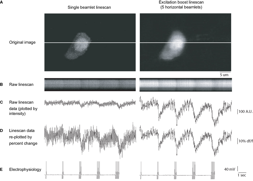
Figure 3. Line scanning with a horizontal DOE. Line scan imaging using horizontal DOE scanning. (A) Full-frame raster scan images of a neuron filled with Fura 2 pentapotassium salt acquired using traditional single beam excitation (left) and five beamlet excitation (right). Note that with multiple beamlets there is slight blurring of the image of the neuron, however the narrow spacing minimizes this blurring to the extent that the cell is clearly distinguishable. These images were used to select a level for line scanning (white horizontal line in each image). (B) Line scans acquired at 80 scans per second using single beam (left) and multibeam (right) excitation, time is represented in the horizontal axis, each vertical column represents one scan. A limited spatial extent of the line scan which includes the cell soma is shown for display purposes. The neuron was patch clamped and driven to fire action potentials during the optical recording. (C) Intensity versus time profiles of linescans shown in (B). Raw brightness intensity scales identical in left and right graphs in arbitrary brightness units. Calcium transients are visible corresponding to times of action potential firing indicated in the whole cell patch clamp current clamp trace shown in (E). The cell was induced to fire increasing numbers of action potentials starting with 1 and ending with 5. Calcium transients grew monotonically in correspondence to the number of action potentials in both imaging regimes but can be seen more clearly in the five beamlet case. (D) Same data as in (C) but re-plotted such that percent change from baseline (DF/F) is equivalent for both traces. Note that calcium transients induced by a given number of spikes are the same amplitude in both conditions, however noise is decreased in the five beamlet case, rendering a greater signal to noise ratio with DOE imaging. Signal to noise ratio was improved by 1.91 ± 0.24 fold (n = 5 signals) in the excitation boost DOE imaging results shown versus the single beam imaging.
When employing DOE scanning, we found a significant increase in the S/N of calcium transients, as compared with conventional scanning, as one would expect from multiple excitations of the fluorophore by the multiple beams, each of them having a similar power as the original beam. For simplicity, we defined the S/N as the ratio between the peak fluorescence to the standard deviation of the resting fluorescence, and measured it for regimes of stimulation ranging from one to five action potentials. With conventional single-beam scanning (Figure 3
, left), the fluorescence responses associated with individual action potentials were barely distinguishable from background fluorescence (Figure 3
: average S/N = 1.01 ± 0.35, n = 5 trials). In contrast, when scanning with multiple beamlets, a single action potential, generated with an identical physiological protocol (Figure 3
D), was readily distinguishable (Figure 3
, right panel; average S/N = 1.95 for response shown). Similar results were obtained with varying increasing numbers of action potentials (for neuron shown, improvement of S/N for 1, 2, 3, 4, and 5 APs were 1.84, 2.32, 2.06, 1.77, and 1.63 fold respectively, with an average of 1.91 ± 0.24 fold). Overall, we found that S/N ratio was improved 1.85 ± 0.13 fold (n = 19 APs signals from three neurons). These increases in S/N are within the range expected from a fivefold increase in total excitation (2.23-fold S/N increase expected in an ideal system assuming no additional factors, such as non-linear effects, saturations, or other sources of noise). Finally, as one would expect from the spatial spread of the excitation light, the full-frame image of the sample, acquired with a conventional PMT full-frame scanning, was spatially less precise in the DOE beamlet scanning, than in conventional single beam scanning, with a blurring of contours and loss of finer spatial detail of the image (Figure 3
A left versus right panel).
Based on these results, we concluded that the spatial multiplexing with a horizontal DOE can increase the S/N of the calcium imaging of action potentials, although at the expense of a small degradation of the spatial quality of the image.
Improvement in Signal to Noise in Two-Photon Frame Scans
To further explore the use of increasing the effective excitation with a DOE, we performed imaging of action potentials evoked in neurons in neocortical slices, but using a full-frame PMT detection mode, instead of a line scan mode (frame scan; Figure 4
). We scanned each line in the image with either one or five horizontally oriented beamlets, while simultaneously stimulating one of the neurons with depolarizing currents that elicited pairs of action potentials (Figure 4
, arrows). As expected, the five-beamlet trials generated fluorescence transients in the soma of the depolarized neuron that were larger than the conventional scanning trials. Specifically, we found a 1.96 ± 0.72 fold enhancement in S/N after performing all-to-all comparisons of signal to noise ratios for signals shown in Figure 4
. Results from a total of 45 AP signals from two cells in two separate slices yielded similar results with a per-cell improvement in signal to noise of 1.4 ± 0.02 fold. The increase in S/N is also within the range one would expect from a fivefold increase in intensity, with the caveats mentioned above.
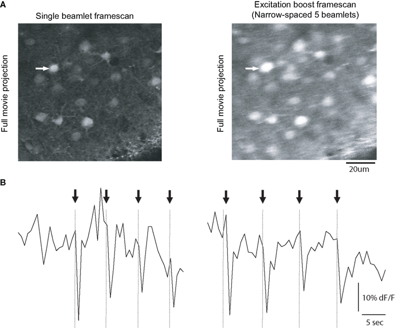
Figure 4. Enhanced frame scan with a DOE. Full-frame calcium imaging using horizontal DOE mode. (A) Full-frame raster scan images of a population of neurons bulk loaded with Fura 2-AM calcium indicator dye acquired using traditional single beam excitation (left) and five beamlet excitation (right). Horizontal DOE mode slightly decreases spatial resolution but not to the extent that resolution of single cells is problematic. Images in the top row are the product of average pixel-wise projection of a movie. (B) Intensity versus time profiles of time-lapse movies of shown field of view for the cell indicated by arrow in (A). Scales identical in left and right graphs, vertical axis in arbitrary brightness units, horizontal axis in seconds. The neuron of interest was patch clamped was driven to fire sets of three action potentials during the optical recording and calcium transients are visible corresponding to times of action potential firing (indicated by arrows and vertical lines). Signal to noise ratio was improved by an average of 1.95 ± 0.72 fold in the excitation boost multibeam excitation boost frame scan mode relative to single beam imaging.
The images obtained with the five beamlet scanning demonstrated overall higher fluorescence values, as expected from the increase in overall integrated excitation, as well as some degradation of the spatial resolution of the image, as expected from the spread of the excitation PSF.
Fast Calcium Imaging of Neuronal Circuits with DOEs with Vertical DOEs
Finally, we explored the use of DOEs to increase the scanning speed of two-photon imaging, by positioning 11 DOE beamlets in a vertical arrangement (Figure 1
bottom), thus scanning the full sample in roughly 11-fold less time (in fact up to 22× less time, because in regular raster scanning mode the Fluoview software does not collect data during the horizontal flyback of the beam). For these experiments, we used a CCD camera as a detector, and spaced the beamlets apart from each other so that they covered the inter-scan territories and adequately covered the entire image (Figure 5
A). As a practical comparison, we carried out a typical “conventional” non-DOE experiment, using a single beamlet with PMT detection as well as vertical mode DOE scanning with camera detection and performed identical stimulation protocols for both cases, eliciting increasing numbers of action potentials using a patch clamp pipette in the same imaged neurons. The acquisition rate was 1 Hz using traditional scanning, and, for comparison, we acquired full field images at 10 Hz using DOE scanning. These two imaging regimes were carried out such that the pixels dimensions and dwell time per pixel of both types of images were equivalent – with a single 256 × 256 pixel scan of the entire field of view for both imaging modes and with the same galvanometer mirror speed used in both experiments.
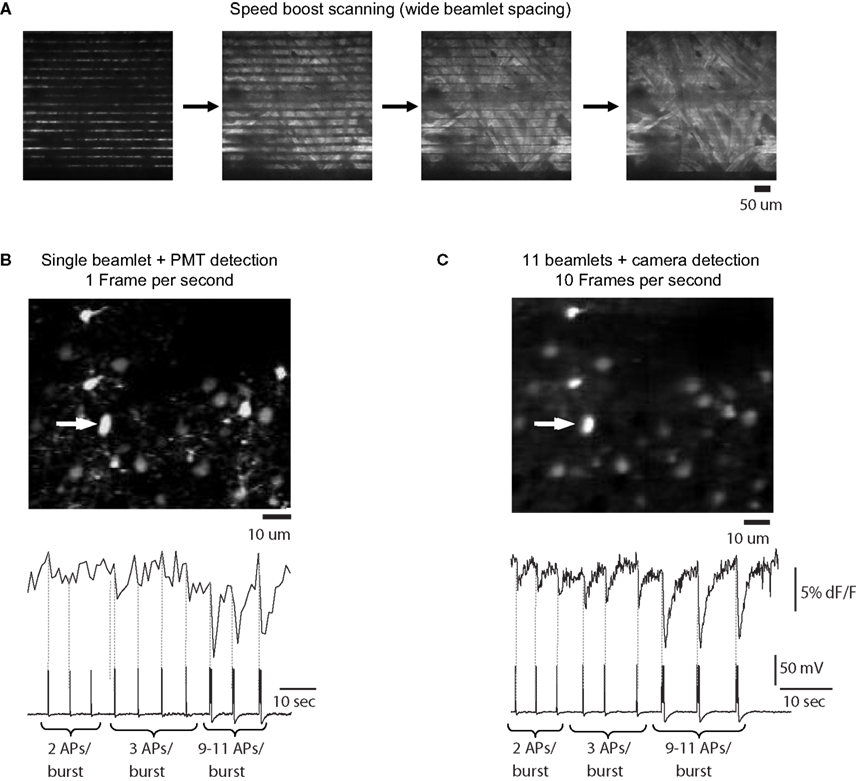
Figure 5. Scanning with vertical DOE. Full-frame calcium imaging using vertical (speed-boost) DOE scanning. (A) Progressive full-field scanning of a paper sample using many beams spread vertically over the field of view and captured with a CCD camera. At left is a “line scan” which creates a number of lines of excitation equal to the number of beamlets. Moving right, a demonstration of the scanning performed by this system: the beamlets are allowed to scan for a longer time with each image, eventually covering the entire field of view with each frame capture by the camera. (B) Full-frame scanning of a patch clamped neuron using a traditional single beam with PMT detection. Movie acquired at one frame per second. Below is intensity versus time profile and patch clamp recording for cell indicated by arrow which was driven to bursts of increasing numbers of action potentials (number of action potentials per burst indicated below trace and timing indicated in imaging trace with dotted vertical line). Vertical axis of brightness trace in arbitrary brightness units, horizontal axis in seconds. (C) Vertical DOE scanning of a population of neurons using 11 beamlet excitation and imaging with a CCD camera. Movie collected at 10 frames per second. Note that calcium transients corresponding to times of bursts of two or three action potentials are easily visible in the calcium indicator tracing produced by DOE-based imaging and are less clear with single beam raster scan. Furthermore, while calcium transients produced by 9–11 action potentials per burst were easily distinguishable in both cases, they were found o have a 2.15-fold greater signal to noise ratio in the case of speed boost imaging.
We found that DOE beam multiplexing not only made scanning faster, but also increased the S/N of the action potential signals by 1.80 ± 0.33 fold (n = 19 signals from three separate cells). This was likely due to the additional acquisition of fluorescence during the flyback by the camera imaging, although quantitative comparisons between the two types of experiments are difficult given the significant differences in detection devices used. In the example shown in Figure 5
, in single beam imaging mode two- and three-action potential bursts produced signals which were difficult to distinguish from noise, while in speed boost mode these signals were easily visible. Signals generated by bursts of roughly 10 action potentials were easily distinguishable in both imaging modalities, but even these latter had an approximately 2.15-fold greater S/N in multibeam imaging compared to single beam imaging. The spatial details of the image were comparable between both cases.
We concluded that DOE beam multiplexing can be effectively used to increase the speed of two-photon laser scanning.
Laser Scanning with DOEs
We describe the use of DOEs for enhancing two-photon imaging as applied specifically to calcium imaging and, more broadly, to biological time-lapse imaging. This approach takes advantage of the fact that most femtosecond lasers produce more laser power than is needed for standard two-photon imaging. By distributing this excitation power into multiple beamlets that simultaneously scan the sample, but are spread over space and time, one can obtain more signal per unit time and scan faster.
We used two different spatial configurations of beamlets created by the DOE to achieve either an increased excitation of the sample, or greater imaging speed. In the horizontal (excitation boost) mode, we excite every point in the sample several times, once with each DOE-produced beamlet. This essentially convolves the traditional single beam-based two-photon imaging result with the spatial function created by the DOE. This improves the S/N, by increasing the signal strength per pixel, integrated over time, as demonstrated here by the detection of action potential-related calcium indicator transients from neurons. We show how horizontal DOE scanning can be used both for linescan and for full-frame raster scan types of imaging, as long as a small amount of degradation of spatial signal can be tolerated in a single user-defined dimension. Although in theory one could increase the intensity of the laser and achieve the same result with single beam scanning, this is not a practical alternative given that photodamage and photobleaching are easily induced, in our experience, with power levels relatively close to the ones used in a typical experiment. Also, increasing laser intensity has the fundamental limit of chromophore saturation, beyond which no additional signal will be obtained. Therefore, splitting the laser power in time, using horizontal DOE scanning, can avoid these problems, but still have the benefit of an increased S/N that results from an increase in integrated excitation. In addition, although one could achieve increased S/N by spatially or temporally averaging the signals after imaging, the “temporal averaging” resulting from the horizontal DOE excitation appears superior since no additional sources of noise are present in the image acquisition, which would be propagated in post hoc spatial or temporal averaging. Horizontal DOE mode appears to be a good compromise between maintaining temporal resolution, imparting only minimal spatial resolution decrements and not surpassing instantaneous photodamage or chromophore saturation thresholds while imparting increased signal to noise ratios.
In vertical DOE (speed boost) mode, we return to sampling each point once per frame but utilize the simultaneous excitation of multiple points to decrease the time needed to do so. By spreading beamlets vertically across the field of view, each beamlet scans a fractional amount of the total field, with the entire system thereby taking only a fraction of the time to image the full field. It is necessary to utilize a camera or similar device to detect signals in this case and it is therefore also necessary to coordinate camera frame acquisition with scanner system frame scanning. Although it is difficult to perform meaningful comparisons between these scanning regime with a camera and single beam scanning with a PMT, our results show that one is able to image calcium indicator-loaded neurons significantly faster than with conventional raster scanning techniques in a similar type of experiment. This method also does not necessarily degrade the spatial resolution of imaging systems since the spatial resolution is determined by the camera utilized for detection.
Relation with Past Work
Our work adds to an increasing number of different strategies that seek to improve the temporal resolution and S/N ratio of two-photon microscopy. Random access scanning (Iyer et al., 2006
; Otsu et al., 2008
; Reddy and Saggau, 2005
; Reddy et al., 2008
) and SLM (Lutz et al., 2008
; Nikolenko et al., 2008
) solve the speed bottleneck by illuminating only selected pixels of the image. An alternative solution, which we pursue here, is to simultaneously scan several pixels at once, by splitting the beam into several beamlets. This can be achieved via use of a system of beam-splitter semi-transparent mirrors mirrors (Kurtz et al., 2006
; Nielsen et al., 2001
), linear multilens arrays or spinning circular lens arrays (Bewersdorf et al., 1998
). DOEs appear to us a highly effective, simpler, less expensive method for laser multiplexing since it requires a single optical element that has a high transmission efficiency. The use of DOEs to enhance laser scanning systems was pioneered by Sacconi et al., who used a custom-made DOE system to obtain two-photon images of cultured cells on a coverslip and enhance image acquisition speed (Sacconi et al., 2003
). Using commercially available and inexpensive DOEs as well as standard commercial scanning software, we follow a similar strategy that results in enhancement of S/N, as well as speed. Moreover, we have extended this strategy and demonstrated its usefulness in one of the common applications of two-photon imaging in neuroscience: the optical detection of fast neuronal activity using calcium imaging.
Our strategy is complementary to the use of temporal laser multiplexing to increase the S/N of two-photon imaging (Ji et al., 2008
). By increasing the repetition rate of a laser source (pulse splitting), Ji et al. also generated a stronger fluorescence signal per imaging period, which resulted in better S/N but without increasing photodamage and photobleaching since the instantaneous power is not above threshold for these phenomena. With a horizontal DOE scanning regime, one can also achieve a similar enhancement, but by multiplexing the laser beam in space, rather than in time. Since the interbeam scanning interval (microseconds) is much slower than the excited states from most fluorophores (nanoseconds), spatial multiplexing can be a useful alternative to pulse doubling. While the temporal multiplexing has the advantage of not decreasing spatial resolution, it appears more complicated to instantiate than the DOEs presented here. In fact, these two methods could be used together, particularly since the speed-boost DOE method enhances the physical speed limitations imposed by moving galvanometer mirrors with non-zero inertia, something not addressed by pulse doubling.
Limitations and Utility of DOE Scanning
We view DOEs as a particularly inexpensive and easily-implemented member of a variety of optical tools that experimentalists can combine to maximize the S/N and speed of their measurements, not only for two-photon fluorescence, but also in principle in other non-linear microscopies. In spite of its usefulness, DOE scanning also has some practical limitations. Because a DOE splits the beam into less powerful beamlets, its use could become power-limited with increasing number of beamlets because of the trade-offs among laser power, number of beamlets, temporal resolution, and desired S/N. For imaging calcium signals with the beamlet regimes we have explored, this does not appear to be a major problem, although for uncaging or photochemical applications, which often use the full power of the laser source, this could become limiting. Another practical limitation is that inexpensive DOEs are only manufactured in finite combinations of number of beamlets, spatial layout and angle of spread, limiting the choice of the experimenter, although this of course can be solved with custom-designed DOEs (Sacconi et al., 2003
). Finally, as mentioned and demonstrated above (Figure 4
), the horizontal DOE scanning can result in spatial blurring.
In vivo imaging of deep mammalian cortex is an example of a situation which is relatively power limited with currently available laser technologies since increased excitation power is often utilized in order to allow high S/N imaging at depth (Oheim et al., 2001
). In such situations multibeam imaging may not be useful, or the number of beamlets used may be reduced to allow sufficient power per beamlet. As increasingly powerful lasers are produced, however, this particular problem will be mitigated. In general this is a highly generalizable and customizable method with few theoretical limitations and which can be engineered to a particular imaging situation by those wishing to employ it.
Given the various options available to enhance two-photon imaging, each with its own advantages and disadvantages, it is appropriate to discuss the situations in which we believe DOE scanning would particularly useful. In general we would recommend it to improve S/N and speed for commercial two-photon systems, since DOE scanning is a relatively simple technique that requires minimal modification to existing laser scanning microscopes, does not require specialized software, and the cost of DOEs is low. In addition, the power transmission through DOEs is excellent, so this strategy may not be so costly in terms of power loss as, for example, SLMs. In fact, with proper design and at the appropriate wavelength some DOEs have a reduced zero- and higher diffraction orders beam, making them even more efficient. Finally, DOEs, which are optically simple, do not significantly distort the temporal profile of the laser pulses, so they could be the method of choice when pulse width is critical.
The authors declare that the research was conducted in the absence of any commercial or financial relationships that could be construed as a potential conflict of interest.
We thank members of the laboratory and anonymous reviewers for useful comments. Supported by the Kavli Institute for Brain Science, the NINDS and the National Eye Institute.
The Supplementary Material for this article can be found online at http://www.frontiersin.org/neuralcircuits/paper/10.3389/neuro.04/006.2009
.