Iridium oxide microelectrode arrays for in vitro stimulation of individual rat neurons from dissociated cultures
1
Institute of Bio- and Nanosystems, Institute 2: Bioelectronics, Forschungszentrum Jülich GmbH, Jülich, Germany
2
Jülich-Aachen Research Alliance - Fundamentals of Future Information Technologies, Aachen and Jülich, Germany
3
Institute of Materials in Electrical Engineering (IWE1), RWTH Aachen University, Aachen, Germany
4
Informatics and Microsystem Technology, University of Applied Sciences Kaiserslautern – Campus Zweibrücken, Zweibrücken, Germany
We present the first in vitro extracellular stimulation of individual neurons from dissociated cultures with iridium oxide (IrOx) electrodes. Microelectrode arrays with sputtered IrOx films (SIROF) were developed for electrophysiological investigations with electrogenic cells. The microelectrodes were characterized with scanning electron and atomic force microscopy, revealing rough and porous electrodes with enlarged surface areas. As shown by cyclic voltammetry and electrochemical impedance spectroscopy, the large surface area in combination with the good electrochemical properties of SIROF resulted in high charge storage capacity and low electrode impedance. Thus, we could transfer the good properties of IrOx as material for in vivo stimulation electrodes to multi-electrode arrays with electrode diameters as small as 10 μm for in vitro applications. Single rat cortical neurons from dissociated cultures were successfully stimulated to fire action potentials using single or trains of biphasic rectangular voltage-controlled stimulation pulses. The stimulated cell’s membrane potential was simultaneously monitored using whole-cell current-clamp recordings. This experimental configuration allowed direct evaluation of the influence of pulse phase sequence, amplitude, and number on the stimulation success ratio and action potential latency. Negative phase first pulses were more effective for extracellular stimulation and caused reduced latency in comparison to positive phase first pulses. Increasing the pulse amplitude also improved stimulation reliability. However, in order to prevent cell or electrode damage, the pulse amplitude is limited to voltages below the threshold for irreversible electrochemical reactions at the electrode. As an alternative to increasing the amplitude, a higher number of stimulation pulses was also shown to increase stimulation success.
Bioelectronic hybrid systems at the interface between biological and electronic information processing can be utilized for electrophysiological studies with dissociated networks of neurons (Gross et al., 1993
; Eytan et al., 2003
; Jimbo et al., 2003
; Wagenaar et al., 2005
; Heer et al., 2007
; Jun et al., 2007
) or brain slices (Novak and Wheeler, 1988
; Egert et al., 1998
; Heuschkel et al., 2002
; Gawad et al., 2009
). For both applications, extracellular stimulation of single cells is desirable to gain precise access to the neuronal network or tissue with a high resolution. At the same time, stable cell-device interfacing requires biocompatible materials and devices that can be used for long-term stimulation without damaging the cells or devices. Two basic approaches can be used in order to achieve this goal.
Firstly, insulated planar electrodes (Fromherz and Stett, 1995
; Schoen and Fromherz, 2007
, 2008
) can be used for the purely capacitive stimulation of cells using voltage ramps or pulses. Secondly, multi-electrode arrays (MEAs) consisting of cell-size adapted metal electrodes have a long history for the voltage-and current-controlled extracellular stimulation of electrically excitable cells (Pine, 1980
; Regehr et al., 1988
; Jimbo and Kawana, 1992
; Gross et al., 1993
; Maher et al., 1999
). For these metallic electrodes, the total stimulation current is significantly increased by a faradaic charge transfer from the electrode to the electrolyte solution in addition to the capacitive current. However, the cell membrane can be depolarized for both kinds of electrodes by stimulation pulses until voltage-gated sodium channels in the membrane open and allow the influx of sodium ions for a self-amplifying depolarization, finally leading to an action potential (Schoen and Fromherz, 2007
, 2008
).
In order to achieve a reliable cell-electrode interface, it is important to use an electrode material that can deliver a high amount of charge into the electrolyte solution underneath the cell. At the same time, cell and device damage must be prevented by using electrode voltages within the safe electrochemical window, where no irreversible electrochemical reactions such as gas evolution occur (Brummer et al., 1983
; Huang et al., 2001
; Merrill et al., 2005
; Cogan, 2008
). In the past, various materials such as platinum (Heuschkel et al., 2002
), gold-plated indium tin oxide (ITO) (Gross et al., 1993
), and titanium nitride (TiN) (Egert et al., 1998
; Eytan et al., 2003
; Wagenaar et al., 2004
, 2005
) have been used for microelectrodes both for stimulation and recording of cell signals. In order to reduce the electrode impedance, platinum (Heer et al., 2007
), ITO (Jimbo and Kawana, 1992
; Jimbo et al., 2003
), and gold (Pine, 1980
; Novak and Wheeler, 1988
; Regehr et al., 1988
; Maher et al., 1999
; Jun et al., 2007
) electrodes have been platinized before usage for stimulation and recording. Recent developments in the field of electrode materials and surface coatings include carbon nanotubes (Wang et al., 2006
; Keefer et al., 2008
; Shein et al., 2009
) and electrically conducting polymers such as PEDOT (Wilks et al., 2009
), which both show good electrochemical properties, but need further investigation concerning their mechanical stability.
A very promising material, which has already a history of application in neuroprosthetics (Rizzo et al., 2003
; Weiland et al., 2005
; McCreery, 2008
) is iridium and especially iridium oxide (IrOx), which can be formed by electrochemical activation of iridium (Robblee et al., 1983
; Aurian-Blajeni et al., 1989a
; Weiland et al., 2002
; Lee et al., 2003
; Gawad et al., 2009
) or by reactive sputtering from iridium in an oxidizing plasma (Schiavone et al., 1979
; Aurian-Blajeni et al., 1989b
; Klein et al., 1989
; Slavcheva et al., 2004
, 2006
; Wessling et al., 2006
; Cogan et al., 2009
). For stimulation electrodes, IrOx results in low impedance and high charge storage capacity in comparison to other electrode materials. This is caused by its porous surface structure, greatly enhancing the electrode surface area, and a fast reversible faradaic reaction between the Ir3+ and Ir4+ oxide states (Slavcheva et al., 2004
; Merrill et al., 2005
; Cogan, 2008
). Furthermore, it is highly biocompatible and very stable in electrolyte solutions (Lee et al., 2003
; Merrill et al., 2005
) making it an ideal material for the interfacing of neuronal tissue and cultured networks. Despite the long history in the field of neuroprosthetics, neither activated nor sputtered IrOx films (SIROF) have so far been applied for electrophysiological experiments with dissociated neuronal cell cultures using MEAs. While the groups working with MEAs did not have access to high quality IrOx films, the groups interested in the material mainly focused on functional electrical stimulation instead. Recently, a first study on extracellular recordings from a brain slice with SIROF MEAs has been reported, though (Gawad et al., 2009
).
In order to prevent damage to the stimulation electrodes and the cells or tissue, the electrode potential has to be kept within the safe electrochemical window for the used electrode material (Merrill et al., 2005
). Extracellular stimulation can be achieved using either current- or voltage-controlled stimulation pulses. While current-controlled stimulation enables precise definition of the current density and injected charge during the pulse, the sensor potential is not directly controlled or limited during stimulation. For voltage-controlled stimulation, the sensor potential is predefined, but the current density and amount of injected charge is not controlled in this case. Thus, voltage-controlled stimulation directly allows preventing harmful reactions at the electrode, while stimulation pulses have to be chosen carefully for current-controlled stimulation to achieve this task (Wagenaar et al., 2004
). Due to weak coupling between cell and electrode, successful stimulation would sometimes require voltages outside the safe electrochemical window. In that case, other stimulation pulse parameters such as the pulse form, frequency, phase sequence (mono- or biphasic pulses, positive or negative phase first), and an increasing number of pulses can be used to increase the probability of stimulation success.
In a previous study, the effect of the pulse phase sequence on stimulation efficiency for voltage- and current-controlled stimulation was investigated using TiN electrodes (Wagenaar et al., 2004
). The authors used either current- or voltage-controlled pulses and evaluated the stimulation success by counting action potential responses within a network of neuronal cells by recording with an array of 60 microelectrodes. Other studies have been using direct intracellular recording to investigate the influence of the pulse amplitude for current-controlled stimulation pulses on the stimulation with MEAs (Jimbo and Kawana, 1992
; Buitenweg et al., 2002
) or the pulse number on the voltage-controlled extracellular stimulation with capacitors (Schoen and Fromherz, 2008
).
In this work, we report the first extracellular stimulation of individual rat cortical neurons from a dissociated culture with IrOx MEAs in vitro. Simultaneous intracellular measurement of the stimulated cell’s membrane potential with patch-clamp recordings in the current-clamp mode (see Figure 1
A) was utilized to directly examine the stimulation effect on the cell. In particular, we investigated the influence of the stimulation pulse parameters (see Figure 1
B) phase sequence, amplitude, and number on the success ratio of action potential excitation (percentage of successful stimulations) and the action potential latency (time delay between onset of the extracellular stimulation pulse and maximum of the action potential) for voltage-controlled stimulation pulses.
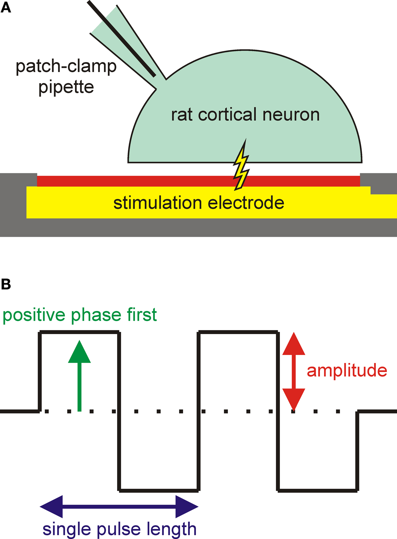
Figure 1. Experimental configuration and varied pulse parameters. (A) Configuration for stimulation experiments. A rat cortical neuron was grown on a microelectrode for extracellular stimulation. The membrane potential of the cell was simultaneously monitored using a patch-clamp pipette in the whole-cell configuration. (B) Single or trains of biphasic rectangular stimulation pulses were used for voltage-controlled stimulation. The influence of three pulse parameters (phase sequence, amplitude, and pulse number) on the stimulation success was investigated. The shown pulse train has a positive phase first and a pulse number of 2.
Multi-Electrode Array Production and Encapsulation
The chips used for this study were based on in-house fabricated gold MEAs, which were manufactured using standard silicon technology as described before (Ecken et al., 2003
). The 64 microelectrodes were arranged in an 8 × 8 matrix with a pitch of 200 μm. The circular electrodes had a diameter of 100 μm for three electrodes in every corner of the chip and 10 μm for the 52 other electrodes. Bond pads, contact lines, and electrodes consisted of 300 nm gold sandwiched by two 30-nm titanium adhesive layers and were fabricated on glass wafers (Borofloat 33, Schott AG, Mainz, Germany) using optical lithography, electron beam evaporation, and a lift off process. A stable passivation against electrolyte solutions was achieved by a stack of 500 nm SiO2, 500 nm Si3N4, and 100 nm SiO2 deposited by plasma enhanced chemical vapor deposition. The microelectrodes and the bond pads were opened by a second optical lithography, reactive ion etching with CHF3 gas, and wet etching of the top titanium layer using a NH4F mixture.
A 20-nm adhesive titanium layer and a 300-nm functional SIROF were deposited on the electrodes for enhanced stimulation capabilities by a third optical lithography and a second lift off process (photo resist n-Lof 2020, Microchemicals GmbH, Ulm, Germany). The amorphous SIROF was deposited by reactive sputtering of iridium in Ar/O2 plasma at room temperature using a Nordiko NS 2550 DC magnetron sputtering system (Control Process Apparatus, Inc., Fremont, CA, USA) with a 6-inch diameter iridium disk of 99.9% purity (Slavcheva et al., 2004
). Before deposition, the sputtering chamber was evacuated to 4 × 10⁻⁶ mbar using a cryogenic pump. A DC-power of 180 W was applied to the target, and the working gas flows were kept at 100 sccm (Ar) and 10 sccm (O2), respectively. During sputtering, the oxygen partial pressure was measured with a Baratron gauge (MKS Instruments, Inc., Andover, MA, USA). The final MEA layer structure is shown schematically in Figure 2
A.
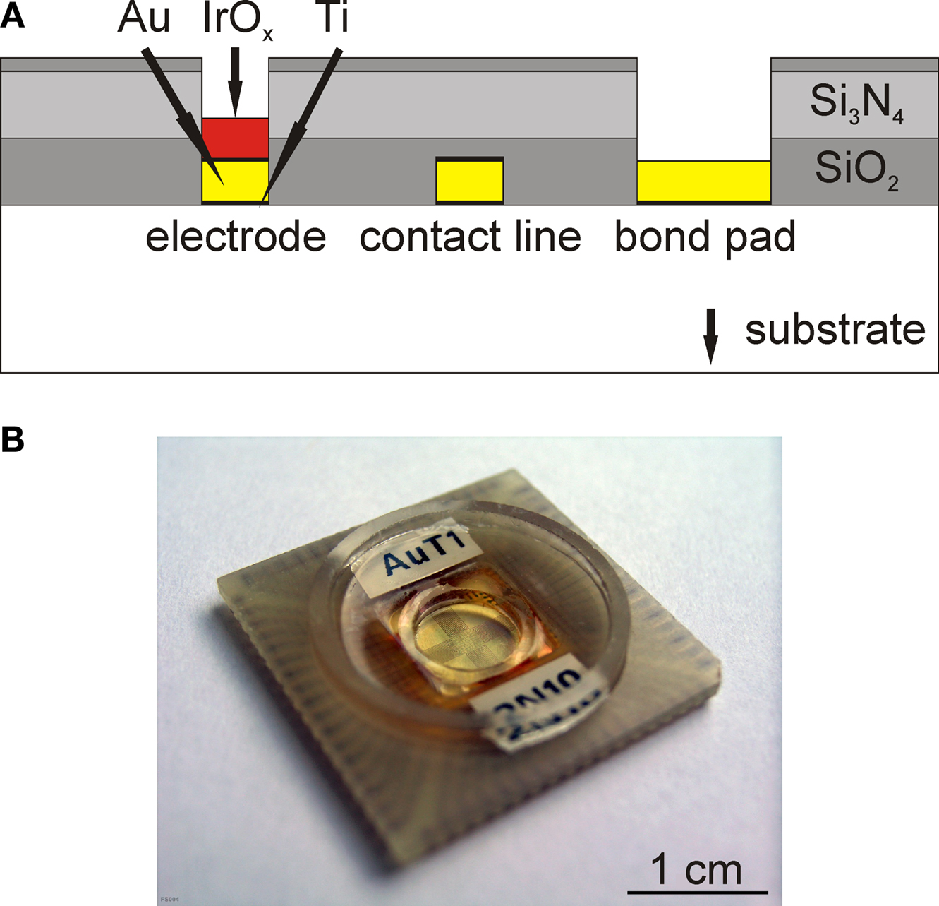
Figure 2. Microelectrode arrays. (A) Layer structure of the MEA chips (not to scale). Electrodes, contact lines, and bond pads consisted of a 300-nm gold layer. The chip was passivated by a stack of 500 nm SiO2, 500 nm Si3N4 and 100 nm SiO2. Electrodes additionally carried 300 nm SIROF to improve the electrode for stimulation capabilities. Thin titanium layers were used to improve the adhesion of gold and SIROF. (B) Completely encapsulated MEA. During the packaging, a cell culture dish on top of the chip surface is formed.
MEA chips with a size of 11 × 11 mm2 were mounted to the backside of 24 × 24 mm2 printed circuit board carriers (WI-KA GmbH, Baesweiler, Germany) with a flip-chip encapsulation procedure that was published before (Ecken et al., 2003
) and is briefly described in the following. First, the chips and carriers were cleaned by 5 min of sonication in a mixture of each 50% (v/v) ethanol and acetone. The electrical contact between the bond pads on the chips and the carriers was formed by precisely printing a conductive two-component silver glue (Epo-Tek H20E-PFC, Polytec GmbH, Waldbronn, Germany) on the contact areas of the carrier using a laser perforated foil in a screen printer (SP-002, Essemtec AG, Aesch, Switzerland). Chips and carriers were then aligned and glued together using a precise X–Y positioning system (Fineplacer 96, Finetech GmbH & Co. KG, Berlin, Germany). The gaps between the contacts were filled with a dielectric two component underfill (Epo-Tek U300, Polytec). A cell culture dish was formed on the chip by two glass rings with inner diameters of 7 and 16 mm and filling the space between the two rings with polydimethylsiloxane (PDMS) (Sylgard 96-083, Dow Corning Co., Midland, USA). The silver glue, underfill, and PDMS were cured after each encapsulation step for at least 1 h at 150 °C. The cell culture dish formed during the encapsulation process resulted in a surface area of 38.5 mm2 for cell culture and could hold up to 600 μl of medium. Figure 2
B shows a completely encapsulated MEA chip with the chip-mounted cell culture dish.
SEM Images and AFM Measurements
Scanning electron microscope (SEM) images and atomic force microscope (AFM) measurements of unencapsulated chips were conducted to investigate the surface structure and roughness of the SIROF on top of the microelectrodes. Furthermore, the edge of the SIROF from a large fractured sample was also imaged by SEM, to show a cross-section of the porous material. For these investigations, the samples were cleaned by sonication in a mixture of each 50% (v/v) ethanol and acetone. SEM imaging was conducted with an LEO1550 SEM (Carl Zeiss SMT AG, Oberkochen, Germany). The AFM measurements were performed with a Nanoscope IV Multimode AFM (Veeco Instruments Inc., Plainview, NY, USA) in tapping mode using n-doped silicon tapping mode cantilevers with a resonance frequency range from 232 to 294 kHz (RTESPW, Veeco Instruments).
Electrochemical Activation and Characterization of the Electrodes
Electrochemical activation and characterization of SIROF microelectrodes were done by cyclic voltammetry (CV) and electrochemical impedance spectroscopy (EIS) with a three-electrode setup with a potentiostat/galvanostat (Autolab PGSTAT100, Eco Chemie B.V., Utrecht, Netherlands) and a frequency response analyzer module (Autolab FRA2, Eco Chemie). A single electrode of a MEA was used as working electrode, a platinum wire with a much larger surface area as counter electrode, and a Ag/AgCl wire as reference electrode. All electrochemical procedures were done in unbuffered 0.9% (w/v) NaCl in bi-distilled water at room temperature. Counter and reference electrodes were immersed into the electrolyte solution in the culture dish on top of the encapsulated MEA chip. In case of CV, the potential of the working electrode was cycled against the potential of the Ag/AgCl wire. For EIS, the measurements were done with respect to open circuit potential, and a sinusoidal input signal with 10 mV amplitude was used to characterize the complex impedance of the working electrode and the electrolyte solution.
Directly after encapsulation, the SIROF electrodes were electrochemically activated by CV with 50 cycles between −700 and +700 mV with a scan rate of 100 mV/s. As frequently shown in literature (Slavcheva et al., 2004
; Wessling et al., 2006
; Cogan, 2008
; Cogan et al., 2009
), this procedure can be used to improve the electrochemical properties of IrOx layers. At the beginning of the activation procedure (approximately the first 10 cycles), the surface and pore structure of the SIROF chips is cleaned from residues of the photolithographic process steps, causing a strong increase of the measured current. After those first 10 cycles, the current slowly further increases by activation of remaining sub stoichiometric SIROF (i.e., more iridium like material) to IrOx. Since the total current usually saturated between the 40th and 50th cycle, all electrodes used in this study were activated with 50 cycles. The last scan of the activation procedure was used to calculate the cathodal charge storage capacity as the area-related integral of the negative current (Cogan, 2008
).
Subsequently, the impedance of the SIROF electrodes was measured by EIS and compared to the impedance of plain and platinized gold electrodes. The electrodes used for the comparison had exactly the same size and were produced in the same production process, only without the deposition of the SIROF stack. The electrochemical platinization procedure was adapted from Thiébaud et al. (1997)
. Briefly, the potential of the gold sample was continuously cycled from 0.1 to −1.0 V for 50 times in the potentiostat with a solution containing 1–2% potassium hexahydroxyplatinate (Platinum 3745 Solution, Engelhard - CLAL Deutschland GmbH, Dreieich, Germany) with a scan rate of 100 mV/s.
Chip Cleaning and Cell Culture
The encapsulated chips with the culture chamber could be repeatedly used for culturing cells and cleaned up to 10 times without any visible damage, except when misalignment of the SIROF and gold electrodes underneath induced device failure by SIROF detachment after continuous exposure to electrolyte solution. The cleaning procedure started with mechanical cleaning with cotton buds and a 70% ethanol solution, and subsequent sonication for 5 min in 2% detergent (Hellmanex II, Hellma GmbH & Co. KG, Müllheim, Germany). After rinsing and additional 5 min sonication with bi-distilled water, the cell culture containers were further cleaned for 20 min at 80°C with 20% sulfuric acid. The sulfuric acid was removed thoroughly by intense rinsing and 5 min sonication with bi-distilled water, and the chips were dried by a nitrogen jet. After sterilization with 70% ethanol for 15 min and with ultraviolet light for 30 min under a sterile clean bench, the sensitive area of the chips was incubated for 1 h with 50 μl of a solution of 0.01 mg/ml poly-D-lysine (PDL) and 0.1 mg/ml extracellular matrix (ECM) gel in Gey’s balanced salt solution (GBSS). Afterwards, the protein solution was removed, and the chips were rinsed once with GBSS (PDL, ECM gel and GBSS by Sigma-Aldrich, St Louis, MO, USA).
Rat embryonic cortical neurons were obtained from embryos of pregnant Wistar rats at 18 days gestation (E18). The embryos were collected and used to isolate primary cells in accordance with German animal protection law (�6 TierSchG), as approved since 2003 by the local district government (Landesumweltamt für Natur, Umwelt und Verbraucherschutz Nordrhein-Westfalen, Recklinghausen, Germany). Cortices were dissected from the embryonic brains and cooled in 1 ml Hank’s balanced salt solution without Ca2+ and Mg2+ (HBSS-), 0.035% sodium bicarbonate, 1 mM sodium pyruvate, 10 mM HEPES and 20 mM glucose at a pH-value of 7.3. The cells were mechanically dissociated by trituration with a fire-polished siliconized Pasteur pipette to avoid cell adhesion at the walls of the pipette. 2 ml HBSS+ (with Ca2+ and Mg2+, supplemented as above) were added. Non-dispersed tissue was allowed to settle for 3 min, and the neuron-containing supernatant was centrifuged at 200 g for 2 min at room temperature. The pellet was resuspended in 1 ml neurobasal (NB) medium with 1% B27 (Brewer et al., 1993
) and 0.5 mM L-glutamine per hemisphere isolated (HBSS, NB medium and all reagents by Invitrogen Co., Carlsbad, CA, USA). An aliquot was diluted 1:4 with trypan blue (0.4% solution, Sigma-Aldrich) and dye-excluding cells were counted in a Neubauer counting chamber. The remaining cells were diluted in NB medium with the above supplements, and 20,000 cells were plated in 50 μl medium on the sensitive area of each chip. After 1 h incubation time at 37°C and 5% CO2 atmosphere, the chips were filled with 600 μl of NB medium. Half a cover slip with a 7 days in vitro (DIV) co-culture of neuronal cells was placed on the chip to supplement neuronal growth factors and to increase the number of cells in the culture. The chips with the cells were kept at 37°C and 5% CO2 atmosphere, and half of the culture medium was exchanged every 3–4 days. The co-culture cover slips were removed and all experiments were performed at 6–10 DIV.
Intracellular Electrical Recording
Prior to electrophysiological measurements, the cell culture medium was replaced by an extracellular recording solution containing (in mM) 130 NaCl, 3 KCl, 2 CaCl2, 1 MgCl2, and 10 HEPES, which was adjusted to a pH-value of 7.3 with NaOH. For each individual chip, the osmolality of the recording solution was adjusted to the measured osmolality of the culture medium with D+ glucose. Micropipettes with resistances between 4 and 6 MΩ were pulled from fire-polished borosilicate glass (BF150-86-10, Sutter Instrument Co., Novato, CA, USA) using a laser puller (P-2000, Sutter Instrument) and filled with an intracellular recording solution consisting of (in mM) 120 KCl, 2 NaCl, 4 MgCl2, 4 Na-ATP, 0.2 EGTA, and 5 HEPES, adjusted to a pH-value of 7.3 with KOH (all reagents by Sigma-Aldrich). Standard whole-cell patch-clamp recordings were conducted using an EPC 10 Double amplifier (HEKA Elektronik Dr Schulze GmbH, Lambrecht, Germany) with a chlorinated silver wire in the pipette as patch electrode. Another chlorinated silver wire was used as reference electrode in the bath solution and kept at ground potential during the measurements. The pipette capacitances were compensated after seal formation, and the membrane capacitances, series resistances, and leakage currents were compensated after establishment of the whole-cell configuration. All measurements were performed at room temperature (22–24°C).
Extracellular Electrical Stimulation
For extracellular stimulation, voltage pulses were applied between one selected SIROF microelectrode and the reference electrode using an altered version of our previously published MEA amplifier system (Ecken et al., 2003
; Wrobel et al., 2007
; Yeung et al., 2007
). The amplifier system was modified to allow stimulation pulse generation by an analog output of the data acquisition card (PCI-6071E, National Instruments Co., Austin, TX, USA) and application to the selected electrode. The card’s output impedance of <0.1 Ω (manufacturer’s specifications) and the impedance of the stimulation circuit in the range of 100 Ω are significantly lower than the electrode impedance. In combination with the specified setting time for full scale steps (3 μs), this guarantees that the stimulation pulse is quickly and completely applied to the electrode. The stimulation software for pulse definition and electrode selection was programmed in LabVIEW (National Instruments) and was also used to trigger the data acquisition by the patch-clamp amplifier. Before every stimulation experiment, the electrode was depolarized by forcing the potential to 0 V against the reference electrode for at least 10 ms to ensure stable conditions.
In all stimulation experiments, biphasic rectangular voltage-controlled pulses were used. Voltage-controlled stimulation was chosen to prevent harmful and damaging high electrode potentials (Wagenaar et al., 2004
; Merrill et al., 2005
), but the biphasic pulses cannot be guaranteed to be charge-balanced. For the evaluation of the effect of other stimulation pulse parameters, the pulse duration was kept constant at a value of about 133 μs (pulse frequency 7.5 kHz).
An overview of the examined pulse parameters is shown in Figure 1
B. As previously described by others (Wagenaar et al., 2004
), the stimulation efficiency can be influenced by the order of the positive and negative phase within biphasic voltage pulses (pulse phase sequence). Therefore, stimulation pulses with positive phase first were compared to pulses with negative phase first. As second parameter, the pulse amplitude can be analyzed in regard to its impact on stimulation efficiency. One major goal of this study was to achieve extracellular stimulation avoiding irreversible electrochemical reactions at the electrodes and gas evolution by electrolysis. Hence, we limited the stimulation amplitude to values of less than ±800 mV, which can be considered safe for SIROF. Instead of further raising the pulse amplitude of single pulses, the probability for action potential excitation can be increased by using trains of pulses instead. As shown in the literature, repetitive weak activation of ion channels by trains of stimulation pulses is a method to stepwise depolarize the cell membrane to reach the threshold potential for a self-amplifying depolarization and the activation of action potentials in single cells (Schoen and Fromherz, 2008
). This effect is based on the asymmetric voltage dependence of sodium channel conductivity (Hodgkin and Huxley, 1952
) and can be explained by the theory of periodic electrical stimulation (Gildemeister, 1944
; Bromm and Lullies, 1966
; Bromm, 1968
; Schoen and Fromherz, 2008
). In this work, pulse trains of up to six pulses were used for the stimulation of individual cells.
Microelectrode Characterization
SEM imaging and AFM measurements
First, the unencapsulated MEAs were investigated by SEM imaging before activation. Figure 3
A shows an SEM image of a microelectrode with a diameter of 10 μm. Most electrodes were completely covered with a rough and porous SIROF, significantly increasing the surface area in comparison to a planar electrode. A few electrodes showed defects such as ruptured or detached SIROF stacks, probably originating from the lift-off process used for structuring of the SIROF. Figures 3
B,C show two SEM images of the rough SIROF surface (Figure 3
B) and the edge (Figure 3
C) of a larger fractured substrate covered with the same SIROF stack. Columnar microstructures separated by voids can be seen in the cross-section of the material, being the reason for the development of the rough surface.
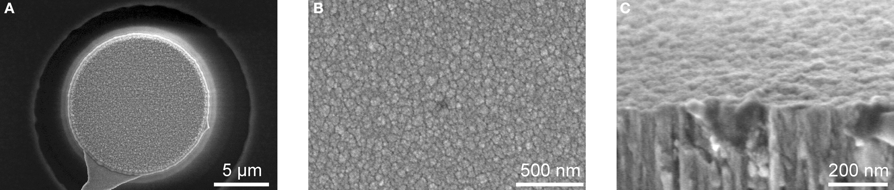
Figure 3. SEM images of SIROF microelectrodes and thin films. SEM images of a whole 10 μm microelectrode (A), a magnification of the SIROF surface (B), and the edge of a large fractured SIROF sample (C) before activation. For all three images, the typical grainy surface structure of SIROF can clearly be seen. The cross-section in (C) also shows the grown columnar microstructure of the SIROF, explaining the rough surface topology.
In the next step, a SIROF microelectrode from an unencapsulated chip was used for an AFM measurement to investigate the structure and the surface roughness of the electrodes. Figure 4
A shows an example of an AFM measurement of a square surface area with an edge length of 1.25 μm of the electrode surface. The typical grainy surface structure known from the SEM measurements can also be seen in the AFM measurement. As visible in the magnification in Figure 4
B, most parts of the surface look homogenously structured with a measured surface roughness of approximately 1.2 nm (root mean square). However, investigating larger surface areas, significantly elevated isolated regions of the surface with peak-to valley distances of more than 150 nm can be identified. Thus, the overall surface roughness is increased to more than 10 nm (root mean square) for larger areas.
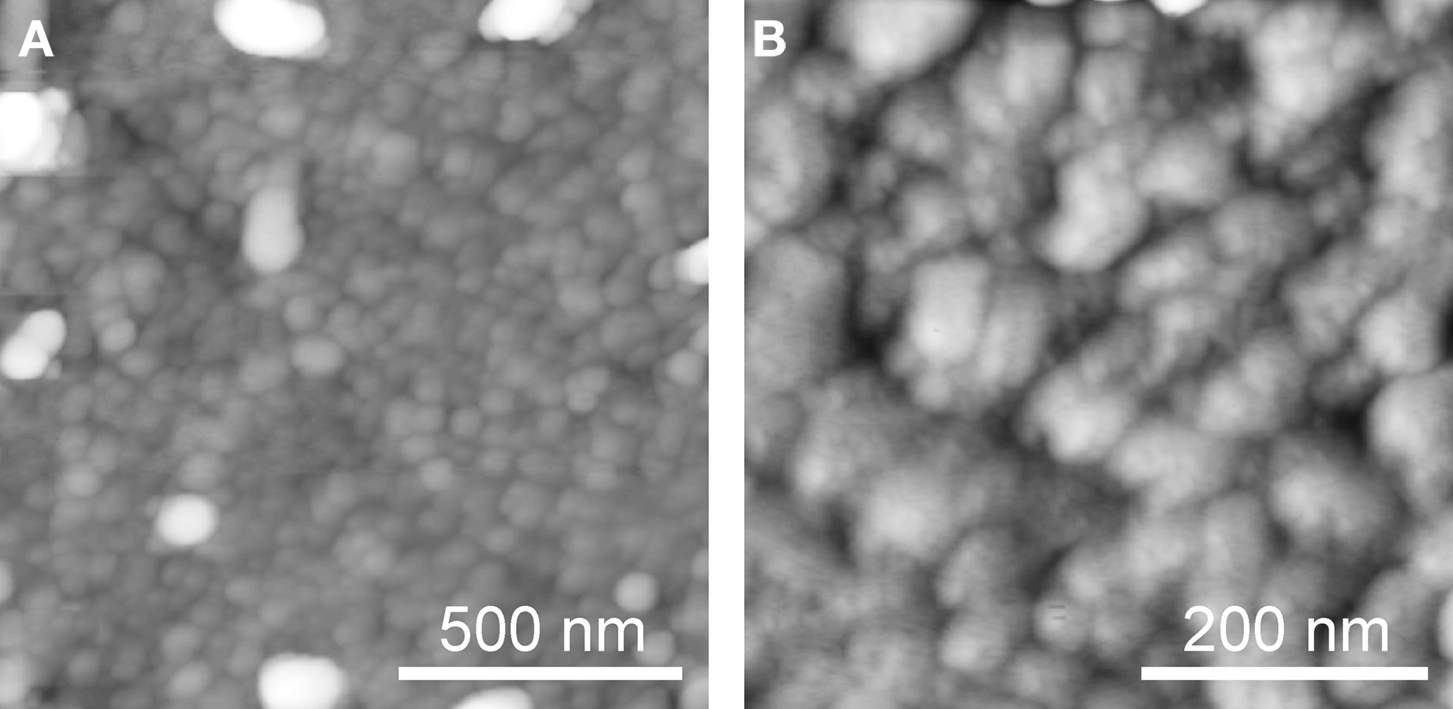
Figure 4. AFM measurement of the surface of SIROF microelectrode. AFM measurements of square surface areas with edge lengths of 1.25 μm (A) and 500 nm (B). The typical rough and grainy surface structure of the SIROF can be seen for both magnifications, with isolated surface areas elevated more than 150 nm. The contrast scale with 256 gray values corresponds to 100 (A) and 25 nm (B).
Electrochemical characterization
Figure 5
shows the last of 50 cycles from the CV activation procedure conducted with two SIROF microelectrodes with diameters of 10 and 100 μm. This last scan was used to calculate the cathodal charge storage capacity, which was found to be 4.91 and 7.99 mC/cm2 for the 100 and 10 μm electrodes, respectively.
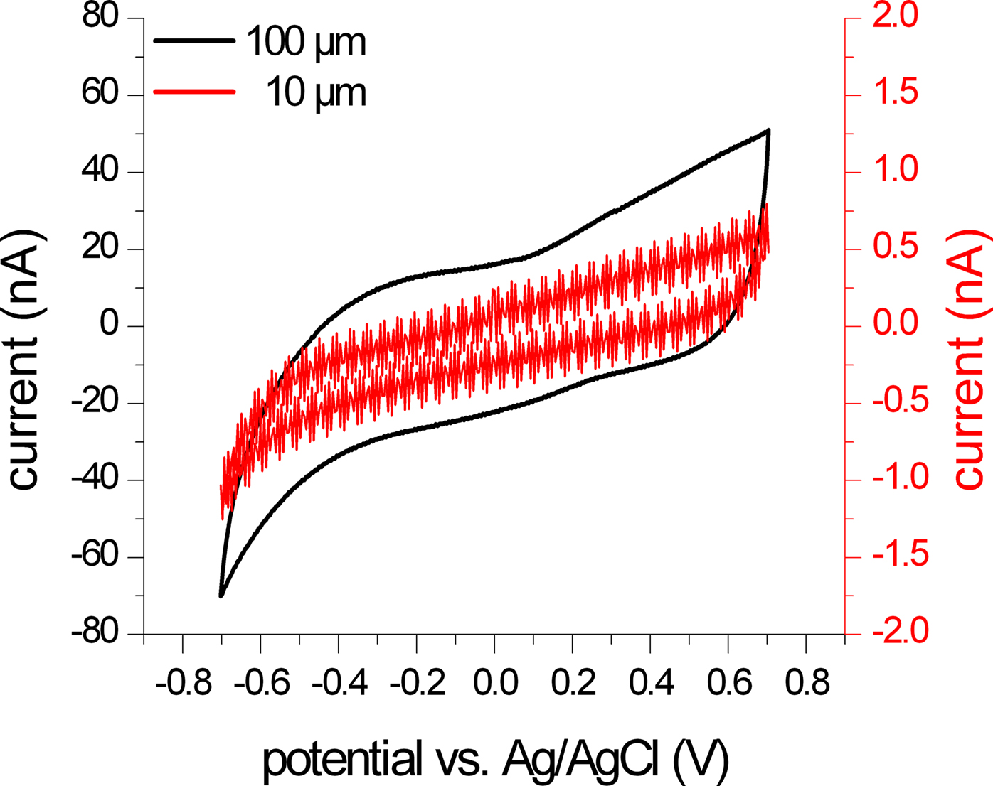
Figure 5. CV scan of two differently sized SIROF microelectrodes. The graph shows the last scan of the activation procedure of two microelectrodes with diameters of 10 μm (red trace) and 100 μm (black trace). The negative current of these two scans was used to calculate the cathodal charge storage capacity of the electrodes. As expected, the signal amplitude is significantly reduced for the smaller electrode (note the difference in the scale for both current measurements). The measured current is close to the resolution limits of the measurement setup and shows signal fluctuations and steps due to noise and distortion, e.g., from the mains frequency.
The impedance of an activated SIROF microelectrode with a diameter of 100 μm measured by EIS is presented in Figure 6
. For comparison, two impedance scans of a gold electrode of the same size without SIROF stack before and after platinization are included, as well.
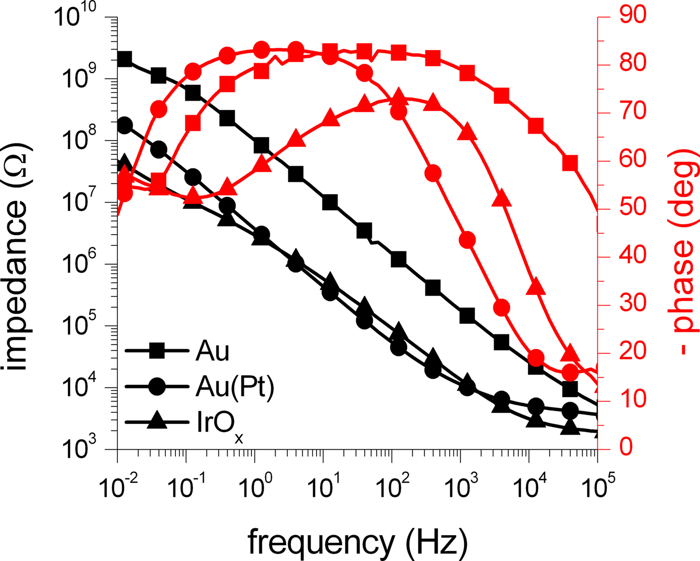
Figure 6. Impedance measurements of microelectrodes with three different electrode materials. The amplitude (black traces) and phase (red traces) of the impedance of 100 μm electrodes acquired through EIS measurements is shown. The impedance of a gold electrode (squares) was significantly reduced by more than one order of magnitude by platinization (circles). The impedance of the activated SIROF electrode (triangles) was in the same range as the impedance of the platinized electrode. The symbols denote every fifth data point.
The two impedance scans for the gold electrode show that the impedance is reduced by the platinization by more than one order of magnitude due to an increase of the surface area. For high frequencies above 10 kHz, the impedance measurements get dominated by the resistance of the bath electrolyte between the working and the counter electrode, causing convergence of both scans. The activated SIROF electrode behaves very similar to the platinized gold electrode and also shows significantly reduced impedance in comparison to the plain gold electrode of the same size. Similar to the scans from the gold electrode, the high-frequency impedance is dominated by the resistance of the bath electrolyte.
Figure 7
shows a comparison of impedance measurements of two activated SIROF microelectrodes with a diameter of 10 and 100 μm. As expected, the impedance of the smaller electrode is significantly increased, but resembles the shape of the impedance scan of the 100 μm electrode. Only in the high frequency range, the influence of the resistance of the bath electrolyte is less dominant in comparison to the impedance scan of the large electrode. For the four investigated electrodes, the impedances at a frequency of 1 kHz were found to be roughly 180 kΩ (gold, 100 μm), 11 kΩ (platinized gold, 100 μm), 14 kΩ (SIROF, 100 μm), and 1.4 MΩ (SIROF, 10 μm).
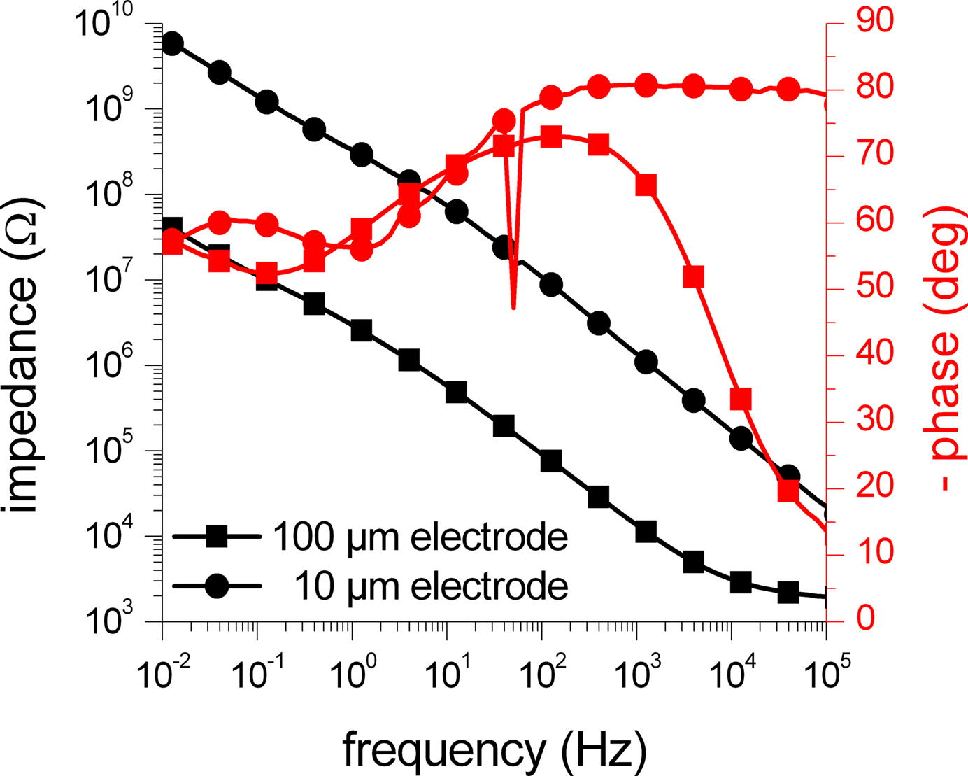
Figure 7. Impedance measurements of SIROF microelectrodes with two different electrode diameters. The amplitude (black traces) and phase (red traces) of the impedance of SIROF electrodes with a diameter of 10 (circles) and 100 μm (squares) acquired through EIS measurements is shown. As expected, the impedance of the smaller electrode is roughly increased by a factor of 100, corresponding to the decrease of the electrode surface area. The glitch at 50 Hz is caused by electromagnetic interference (mains frequency). The symbols denote every fifth data point.
Electrophysiology
The SIROF MEAs were used for the stimulation of individual rat embryonic cortical neurons, while simultaneously monitoring the membrane potential intracellularly. In several experiments, seven neurons (DIV 6–10) located on one of the SIROF microelectrodes with a diameter of 10 or 100 μm were successfully patched and stimulated extracellularly. The effect of the three stimulation pulse parameters phase sequence, amplitude, and pulse number on the stimulation efficiency or success ratio and action potential latency was analyzed. The available time for analyzing the stimulation with every cell greatly varies depending on the cell fitness and the time until the cell dies due to the intracellular measurement with the patch pipette. Furthermore, the experimental conditions between measurements with different neurons severely vary in terms of cell fitness, position on the electrode, and coverage of the electrode. These variations in the experimental conditions and the available time make a statistical analysis of the results very difficult. Therefore, only the results of the stimulation experiments with one particular neuron were taken into account for this evaluation. This particular cell showed good cell fitness and provided a long experimental time for a high number of stimulation experiments. Due to the variation in the experimental situation between experiments, the results from this study cannot be used to give absolute numbers for ideal pulse parameters, but to show general tendencies for the influence of these parameters on the stimulation outcome. Nevertheless, similar trends for the influence of the three investigated stimulation pulse parameters were observed with the other cells as well.
All further experimental data presented in this work was measured with a DIV 7 rat cortical neuron, which was cultured on a 10-μm SIROF microelectrode (Figure 8
). The cell was located at the edge of the electrode, partly covering it. Before extracellular stimulation, the cell activity was tested using standard voltage-clamp and current-clamp protocols, which proved a healthy neuron with reliable activation of ion channels and excitation of action potentials. The stimulation experiments were conducted in the current-clamp configuration to monitor the membrane potential for action potential excitation. A bias pipette current of −20 pA was injected, leading to a membrane potential of about −55 to −60 mV. However, the actual membrane potential at the beginning of each stimulation experiment was not constant, but permanently fluctuated, which is well known for rat cortical neurons in dissociated networks (Vogt et al., 2003
). Therefore, only the 129 stimulation experiments with a pre-pulse membrane potential within the standard deviation (±6.3 mV) of all measurements from a mean value of −57.4 mV were used for statistical analysis. Cellular responses were only regarded as action potentials if their amplitude was higher than 45 mV and reached a maximum potential of at least −10 mV. Furthermore, only responses with a latency of <16 ms were considered to exclude responses evoked by spontaneous network activity. Within these limitations, 43 stimulation experiments successfully caused the excitation of an AP. The error bars in Figures 9
, 10 and 11
represent the standard deviation.
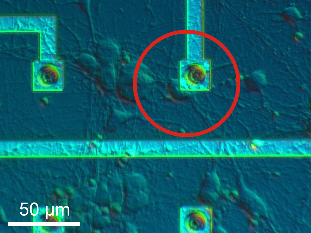
Figure 8. Neuronal cell on stimulation electrode. For stimulation experiments, rat cortical neurons were cultured on SIROF MEAs. The DIV 7 rat cortical neuron in the differential interference contrast image (red circle) grew at the edge of a 10-μm SIROF microelectrode, partly covering it. The cell was patched and extracellularly stimulated.
Pulse phase sequence
Firstly, the effect of the pulse phase sequence on the stimulation success was analyzed. We compared the stimulation efficiency and action potential latency for experiments with biphasic pulses having either positive phase first or negative phase first sequence order. Using the same stimulation frequency, pulse number, and amplitude, we found a higher stimulation probability and lower latencies for negative phase first pulses. Figure 9
A shows the membrane potential during extracellular stimulation with trains of two biphasic pulses (700 mV amplitude). While stimulation with a positive phase first pulse only caused a small depolarization from the initial membrane potential, the negative phase first pulse caused a stronger depolarization resulting in the excitation of an action potential. For both traces, the onset of the extracellular stimulation pulse can be seen by the stimulation artifacts at about 32 and 30 ms, respectively.
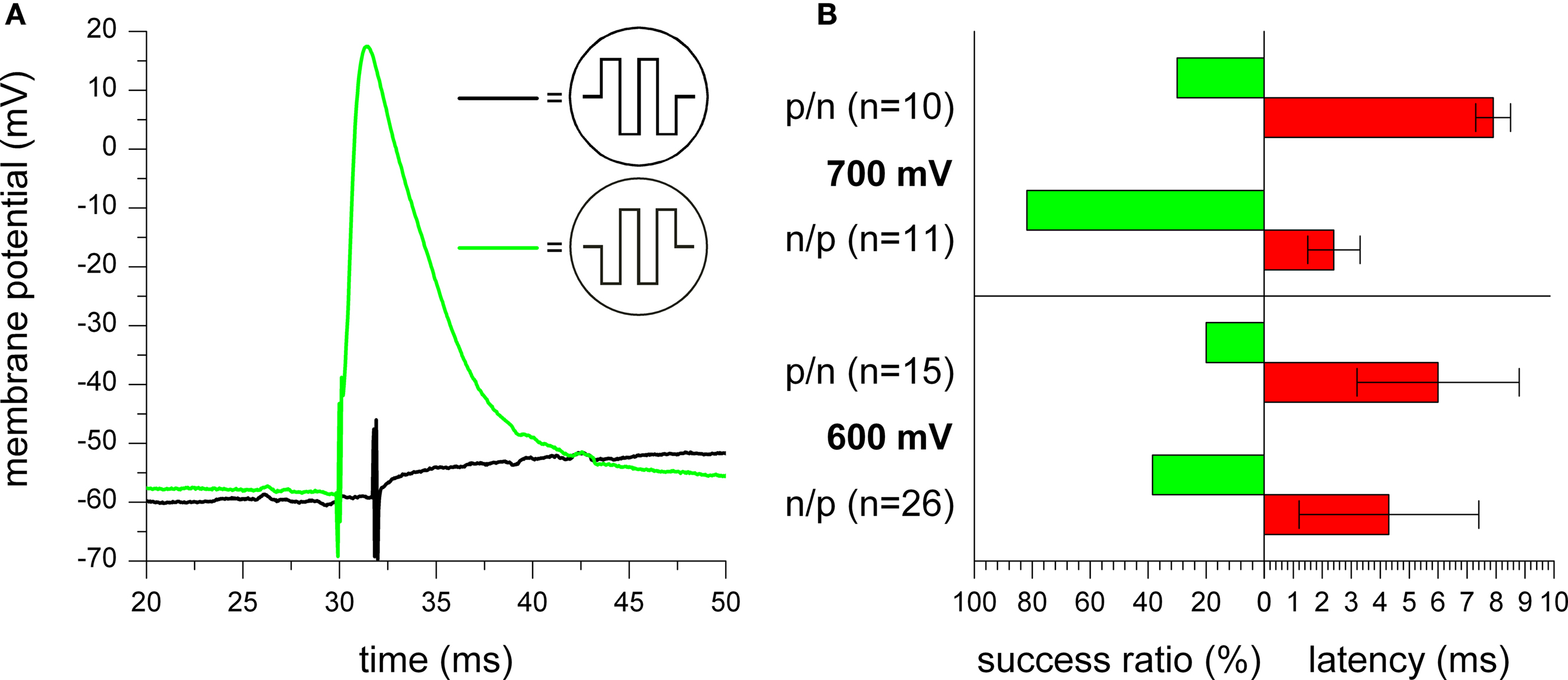
Figure 9. Impact of stimulation pulse phase sequence. (A) Membrane potential of a stimulated cell during application of two biphasic rectangular pulses with 700 mV amplitude with positive (black trace) and negative (green trace) phase first. For both traces, the onset of the extracellular stimulation pulse can be seen by occurrence of stimulation artifacts. As shown with the two examples, no action potential was excited for most positive phase first pulses, while most negative phase first pulses could successfully excite action potentials. (B) Comparison of stimulation success ratio and action potential latency for measurements with positive (p/n) or negative (n/p) phase first pulses at a pulse amplitude of 600 mV (three to five pulses) and 700 mV (one to two pulses), respectively.
Quantifying this result, Figure 9
B shows a comparison of the stimulation efficiency for several measurements with positive or negative phase first pulses at pulse amplitudes of 600 mV (three to five pulses) and 700 mV (one to two pulses), respectively. For both amplitudes, the efficiency of action potential excitation was significantly higher for the negative phase first pulses. Additionally, the latency was also reduced in comparison to positive phase first pulses. However, further measurements indicate that both effects of increased success ratio and reduced latency for negative phase first pulses slowly vanish with increasing number of stimulation pulses (data not shown).
Pulse amplitude
As the second stimulation pulse parameter, the amplitude was investigated. As expected, increasing the pulse amplitude enhances the stimulation success ratio and reduces the latency. While Figure 10
A shows an example of two measurements with one negative phase first stimulation pulse with amplitudes of 600 and 700 mV, Figure 10
B gives a quantitative comparison for experiments with negative phase first stimulation pulses for pulse amplitudes between 500 and 800 mV. For 500 mV, no experiment resulted in a successful stimulation. With increasing amplitude, the stimulation efficiency gradually increased, while the latency decreased at the same time. As can be seen by the large standard deviation for 600 mV, the latency highly varies, thus, limiting the stimulation reliability for low amplitudes. Since stimulation was successful in all cases for pulse amplitudes of 800 mV, it was not further increased to prevent damage to the cell and the electrode.
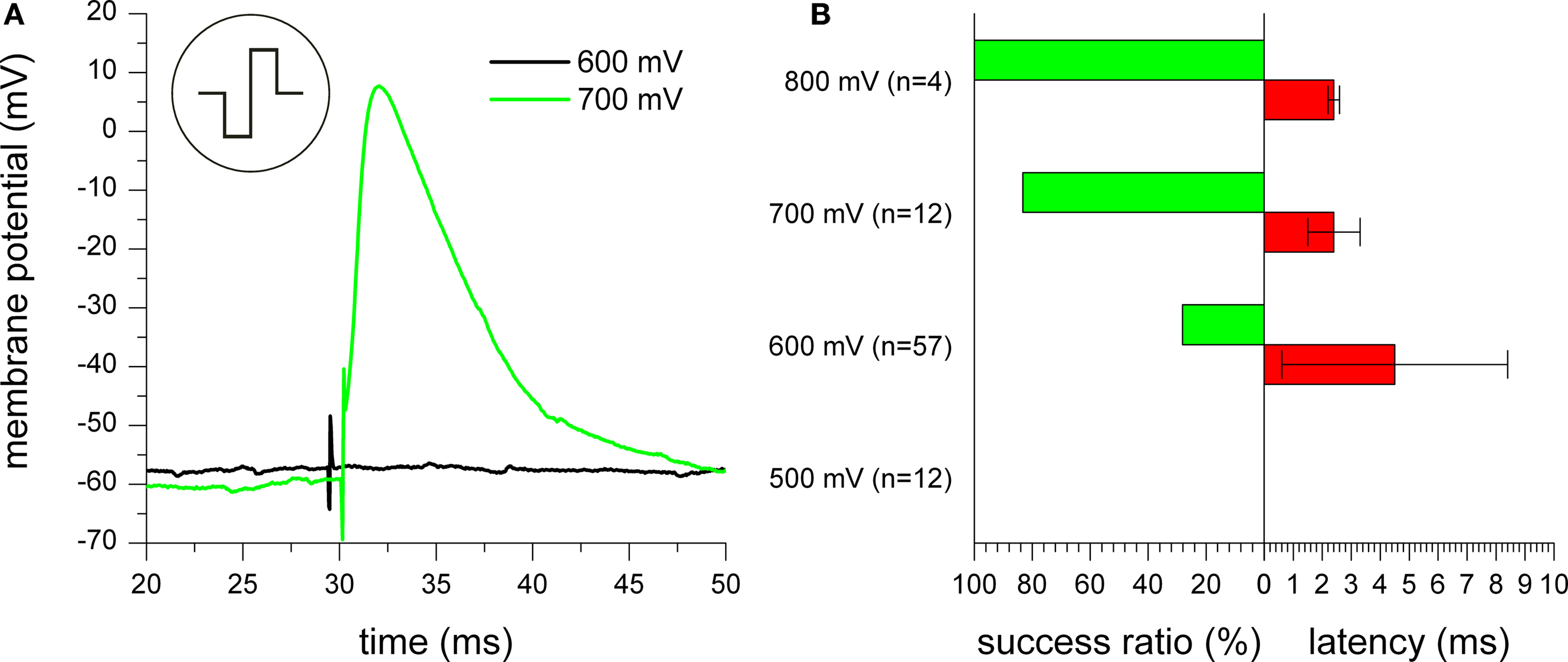
Figure 10. Effect of varying pulse amplitude. (A) Stimulation experiments with one biphasic negative phase first rectangular pulse with 600 mV (black trace) and 700 mV (green trace) amplitude. For both traces, the onset of the extracellular stimulation pulse can be seen by occurrence of stimulation artifacts. For the 700 mV pulse, an action potential was excited. (B) Quantitative analysis of stimulation reliability for experiments with trains of negative phase first stimulation pulses with up to 6 pulses for pulse amplitudes between 500 and 800 mV.
Pulse number
In order to limit the stimulation amplitude within the safe electrochemical window as discussed before, we examined the effect of pulse trains to increase the stimulation efficiency. By using more than one stimulation pulse, the depolarization caused by single pulses adds up, raising the membrane potential step by step above the threshold for action potential excitation. Figure 11
A shows the intracellularly measured membrane potential of the stimulated neuron during application of trains of two, four, or six stimulation pulses with 600 mV amplitude. The onset of the two, four, and six stimulation pulses can be seen by the stimulation artifacts at about 31, 33, and 35 ms, respectively. While two and four pulses were not sufficient to reach the threshold for sodium channel opening, six pulses caused a depolarization which finally led to excitation of an action potential. The inset of Figure 11
A shows a stepwise increase of the membrane potential with each stimulation pulse.
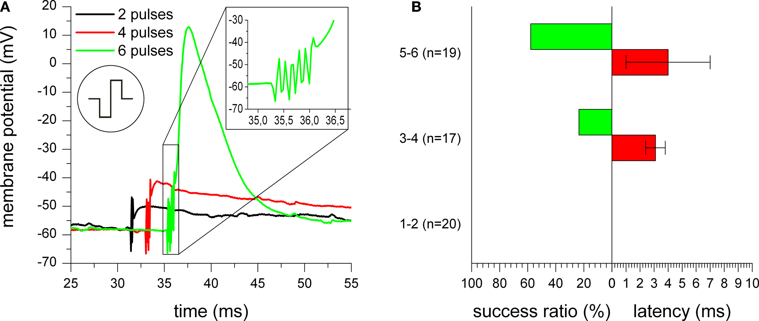
Figure 11. Influence of pulse number used for stimulation. (A) Membrane potential of a cell stimulated with trains of two (black trace), four (red trace), and six (green trace) biphasic negative phase first rectangular pulses with 600 mV amplitude. For all three traces, the onset of the extracellular stimulation pulse can be seen by occurrence of stimulation artifacts. Only for a train of six pulses, an action potential occurred. The inset of (A) shows a magnification of the time of stimulus application with the stepwise increase of the membrane potential from pulse to pulse. (B) Success rate and action potential latency in comparison for stimulation with one to two, three to four, or five to six negative phase first rectangular stimulation pulses with 600 mV amplitude.
Figure 11
B gives quantitative results for the influence of the pulse number on stimulation efficiency and latency of action potentials with negative phase first stimulation pulses and 600 mV amplitude. While stimulation with one or two pulses could never excite an action potential, the success ratio could be increased to about 24% for three or four pulses and even to about 58% for five or six pulses. However, it can be seen that the latency seems to be distributed over a rather large time scale and cannot be reduced by using more stimulation pulses.
MEAs
The results of the SEM imaging and AFM measurements showed the rough and porous surface structure of the functional SIROF, largely increasing the electrochemically active electrode surface area. The imaged microporous surface structure was comparable to IrOx surfaces presented in other studies (Weiland et al., 2002
; Slavcheva et al., 2004
; Gawad et al., 2009
). The surface roughness determined by AFM measurements was found to be in the same range as previously reported values for IrOx films (Blau et al., 1997
, roughness 4–28 nm, peak-to-valley distance 26–250 nm). However, this and other publications showed that the surface roughness severely depends on the production process, and can be further increased by variation of process parameters such as number of activation cycles and oxygen flow during sputtering (Slavcheva et al., 2004
, 2006
). Nevertheless, the surface structure and roughness found for the SIROF on our MEAs was promising for their electrochemical properties.
Examination of the MEAs with CV and EIS measurements revealed the high charge storage capacity and the low impedance caused by the increased surface area and the faradaic charge transfer at the SIROF surface. With values between roughly 5 and 10 mC/cm2, the cathodal charge storage capacity of the microelectrodes was found to be higher than for other electrode materials such as plain and platinized gold, platinum, and TiN and within the range (roughly 1–25 mC/cm2) of other IrOx electrodes (Robblee et al., 1983
; Aurian-Blajeni et al., 1989a
; Klein et al., 1989
; Weiland et al., 2002
; Lee et al., 2003
; Merrill et al., 2005
; Cogan, 2008
). The observed increased charge storage capacity of the smaller electrode can be explained by nonuniform current distributions and transport limitations for larger electrodes (Cogan, 2008
). Even higher values for the charge storage capacity of more than 100 mC/cm2 have been reported in the past (Slavcheva et al., 2004
; Wessling et al., 2008
; Cogan et al., 2009
). Nevertheless, the achieved charge storage capacity severely depends on several material and experimental parameters such as the film thickness, the electrolyte solution, the number of activation cycles, and the potential range used for the calculation of the delivered charge. The variation of these parameters between publications complicates a comparison.
The results of the EIS measurements proved the low impedance of the SIROF microelectrodes in the whole investigated frequency range. The impedance was significantly reduced in comparison to plain and in the same range as platinized gold electrodes. Also a comparison to literature values for TiN electrodes with a similar size reveals similar impedance scans (Wagenaar et al., 2004
, impedance of 50–200 kΩ at 1 kHz for electrodes with a diameter of 30 μm). The increase of the impedance of the 10 μm electrode in comparison to the 100 μm electrode by a factor of 100 corresponds to the decrease in the surface area of the smaller electrode.
In summary, the rough and porous SIROF surface structure in combination with the resulting good electrochemical properties indicate the suitability of the characterized SIROF MEAs for the extracellular stimulation of cortical rat neurons from dissociated cultures in vitro. The charge storage capacity and impedance of the electrodes was found to be good in comparison to other electrode materials, although even better electrochemical properties have been recently reported for novel electrodes with carbon nanotubes (Keefer et al., 2008
) and PEDOT (Wilks et al., 2009
). However, our SIROF MEAs were found to be mechanically stable and could be used for several cell cultures and electrophysiological experiments with subsequent application of the harsh cleaning procedure. This reusability constitutes a significant advantage over the low mechanical stability of surface modifications with platinum black, electrically conductive polymers, and carbon nanotubes. For example, platinum black is usually removed during the chip cleaning step and has to be renewed after every cell culture – a concern that applies to conductive polymers, as well (Wilks et al., 2009
).
Due to the similar fabrication process with a single run reactive sputtering process of a thin film, SIROF is a good candidate to compete with TiN as standard electrode material for MEAs for in vitro electrophysiological studies. Although the initial cost of the sputter target for iridium is higher than for titanium, this difference per device should be marginal in comparison to the total cost of production including operators and maintaining the sputter equipment.
Stimulation Experiments
The SIROF microelectrodes were successfully applied for the extracellular stimulation of individual neurons. In combination with intracellular recordings, stimulation pulse parameters were investigated for their influence on the stimulation efficiency. In our study, negative phase first voltage pulses were found to be more efficient for the extracellular stimulation in terms of success rate and lower action potential latency than positive phase first pulses. This is in contradiction to the results of a previous publication (Wagenaar et al., 2004
), where positive phase first pulses were shown to be slightly more efficient for stimulation. This contradiction of the results could originate in differences in the experimental conditions and the data acquisition (extracellular recording from several cells versus intracellular recording from the stimulated cell).
A possible explanation for the higher stimulation efficiency can be found in the two-domain stimulation model (Schoen and Fromherz, 2007
, 2008
). Here, the cell membrane is divided into the attached membrane, which is in direct contact to the stimulation electrode, and the free membrane. Any voltage applied to the stimulation electrode causes a voltage drop across the cell which is divided between attached and free membrane according to the ratio of both membrane domain’s capacitances (capacitive voltage divider). Since the attached part of the membrane is usually smaller than the free part, the voltage drop across the attached membrane domain is larger. Every voltage applied to the electrode causes depolarization of one membrane domain and hyperpolarization of the other domain.
For a negative phase first pulse, the initial negative voltage causes a hyperpolarization of the large free membrane domain which can remove the partial inactivation of sodium channels in this area. Thus, the following depolarization caused by the fast change to the positive voltage phase can easily excite an action potential in the large free membrane domain if the threshold for sodium channel activation is reached. For the opposite pulse sequence, the large free membrane will first be depolarized and the following hyperpolarization during the second pulse phase can suppress the excitation of an action potential in the large free membrane. Even if an action potential is excited in the smaller attached membrane domain during the depolarization in the second pulse phase, the hyperpolarization in the large free membrane at the same time can block the propagation of the action potential to other parts of the cell (Merrill et al., 2005
). However, this effect of the pulse phase sequence will vanish for an increasing stimulation pulse number, since the influence of the first phase of the first pulse and the initial phase sequence is reduced for later pulses.
As expected, increasing the pulse amplitude also increased the stimulation efficiency if the other parameters were kept constant. At the same time, this improved stimulation success came along with reduced average action potential latency, making the stimulation more reliable in general. Since it is crucial for long-term experiments to prevent damage to electrodes and cells, the stimulation pulse amplitude should be limited to voltages within the safe electrochemical window of the electrode’s material to prevent irreversible electrochemical reactions. In our experiments with SIROF electrodes we achieved reasonable success ratios at voltages as low as 600 or 700 mV and never needed to increase the voltage above 800 mV. However, the necessary pulse amplitude severely depends on the experimental configuration and especially the exact geometry of the cell-electrode contact. Additional experiments with our SIROF MEAs showed reliable stimulation of rat neurons for voltages as low as 300 mV in case of a better cell-device coupling.
A good alternative to amplitude increase for higher stimulation success ratios is the use of trains of stimulation pulses. For every single pulse causing a depolarization higher than the threshold for sodium channel activation, a minor amount of positively charged sodium ions is injected into the cell, generating a small residual depolarization that is left at the end of the pulse. This can lead to a stepwise increase of the membrane potential by summation of residual charges caused by several consecutive stimulation pulses. If the summed depolarization finally leads to a self-amplification, an action potential can be excited. However, repetitive stimulation only suffices to elicit action potentials if two prerequisites are fulfilled: Firstly, the passive repolarization of the cell membrane must be slow enough to leave substantial residual depolarization after each pulse. Secondly, the inactivation of sodium channels must be low enough to leave a sufficient number of excitable channels until the summed depolarization reaches the threshold for channel activation (Schoen and Fromherz, 2008
). Unfortunately, stimulation with a higher number of pulses leads to widely distributed latencies, since the threshold for action potential excitation is reached at a different time of the pulse train for every experiment.
The extracellular stimulation of individual neurons in dissociated cultures is strongly influenced by coupling factors such as geometry of the electrode-cell contact area, which vary for every experiment and cannot be measured beforehand. As shown by the experiments in this work and contradictions to previous publications, it is difficult to find a general rule for the influence of pulse parameters on in vitro stimulation. Therefore, the outcome of any particular stimulation experiment can hardly be predicted, and optimum values for stimulation pulse parameters such as amplitude and pulse number cannot be provided. However, by adjusting those parameters, maximum stimulation reliability can be achieved without causing damage to electrodes and cells.
Within this work, MEAs with functional SIROF for in vitro studies were produced and characterized concerning their surface structure and electrochemical properties. For the first time, IrOx microelectrodes were successfully used for the extracellular stimulation of individual neurons from dissociated cultures. The examination of pulse parameters showed that negative phase first biphasic voltage pulses resulted in a higher stimulation success ratio than positive phase first pulses. In order to prevent damage to electrode and cells, the amplitude of stimulation pulses must be limited to voltages within the safe electrochemical window of the used electrode material. Trains of biphasic voltage pulses with increasing pulse number were shown to further improve the stimulation success if the pulse amplitude cannot be increased anymore.
The authors declare that the research was conducted in the absence of any commercial or financial relationships that could be construed as a potential conflict of interest.
We thank R. Fricke for the neuron culture and N. Wolters and M. Schindler for the amplifier modification. Furthermore, S. Gilles is acknowledged for the AFM measurements. This work was partially funded by the German Research Foundation (Deutsche Forschungsgemeinschaft) on contracts no. OF22/7-1 and SCHN587/5-1 (Mi-BeSAN: Mikroelektronische Bauelemente für extrazelluläre Stimulation und Ableitung von Neuronen).