RideComfort: A Development of Crowdsourcing Smartphones in Measuring Train Ride Quality
 Adam Azzoug
 Sakdirat Kaewunruen
- 1Department of Civil Engineering, School of Engineering, The University of Birmingham, Birmingham, UK
- 2Birmingham Centre for Railway Research and Education, The University of Birmingham, Birmingham, UK
Among the many million train journeys taking place every day, not all of them are being measured or monitored for ride comfort. Improving ride comfort is important for railway companies to attract more passengers to their train services. Giving passengers the ability to measure ride comfort themselves using their smartphones allows railway companies to receive instant feedback from passengers regarding the ride quality on their trains. The purpose of this development is to investigate the feasibility of using smartphones to measure vibration-based ride comfort on trains. This can be accomplished by developing a smartphone application, analyzing the data recorded by the application, and verifying the data by comparing it to data from a track inspection vehicle or an accelerometer. A literature review was undertaken to examine the commonly used standards to evaluate ride comfort, such as the BS ISO 2631-1:1997 standard and Sperling’s ride index as proposed by Sperling and Betzhold (1956). The literature review has also revealed some physical causes of ride discomfort such as vibrations induced by roughness and irregularities present at the wheel/rail interface. We are the first to use artificial neural networks to map data derived from smartphones in order to evaluate ride quality. Our work demonstrates the merits of using smartphones to measure ride comfort aboard trains and suggests recommendations for future technological improvement. Our data argue that the accelerometers found in modern smartphones are of sufficient quality to be used in evaluating ride comfort. The ride comfort levels predicted both by BS ISO 2631-1 and Sperling’s index exhibit excellent agreement.
Introduction
Every day, many million train journeys take place and passengers traveling on these trains are exposed to the vibrations, noises, temperatures, etc. present in the train for the duration of their trips. Passengers will experience the train environment differently based on their individual preferences and expectations. Making passengers feel comfortable aboard their trains is something many railway companies strive to do (Suzuki, 1998; Förstberg, 2000; Karakasis et al., 2005). With the advent of smartphones, passengers can potentially measure the ride comfort themselves. This opens the door for many commercial opportunities, allowing passengers to provide on the fly feedback on the comfort of their journey and equipping railway companies with information they can use to further improve ride comfort for passengers. There is potential for this technology to be used to detect track faults and indicate which sections of track are in need of maintenance, possibly saving on maintenance costs and improving the safety of the railway.
Railway passengers expect a certain level of comfort during their journeys. In general, the comfort of passengers can be affected by a range of different factors such as temperature, humidity, odors, noise, accelerations, and vibrations. The standard BS ISO 2631-1:1997 gives an approximate indication of possible reactions to varying magnitudes of vibration found in public transport, shown in Table 1. It is important to note that passenger reaction to motion is also influenced not only by other factors in their environment such as temperature and noise but also of their expectations, i.e., certain vibrations that are considered comfortable and expected in train journeys might be considered uncomfortable in a car (British Standards Institution, 1997a, BS ISO 2631-1:1997; British Standards Institution, 2001, BS ISO 2631-4:2001; British Standards Institution, 2009, BS ISO 2041:2009).
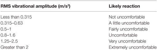
Table 1. Likely passenger reactions to a range of vibration magnitudes according to BS ISO 2631-1:1997.
In this research and development project, we aim to produce a smartphone application that can record the vibrations measured by a smartphone and to investigate how well the smartphone can measure ride comfort aboard trains compared to a more sophisticated accelerometer.
Prior to the development, a critical literature and technology review have been carried out in order to investigate different ways in which ride comfort is measured and evaluated. The review also examines previous products and investigates potential causes of vibrations in trains and also reviews other developments concerning the use of smartphones in measuring ride comfort. In this paper, we will demonstrate the development of smartphone application that can capture internal data and correlate the data with actual onboard sensors using artificial neural networks.
Ride Comfort
Different methods of assessing and quantifying ride comfort have been developed to make it possible to evaluate and predict the ride comfort of a train vehicle based on the vibrations that are experienced inside the vehicle. One of these methods, BS ISO 2631-1:1997 (1997) suggests using a frequency-weighted root mean squared (rms) acceleration to evaluate the ride comfort and is given by
where aw(t) is the instantaneous frequency-weighted acceleration (meters per square second), t is the time (seconds), t0 is the time of observation (seconds), and τ is the integration time for running averaging (seconds). The value gained from Eq. 1 is meant to be compared to the values presented in Table 1, which underlines the relationship between the rms acceleration and expected passenger reaction.
Another widely used method to measure ride comfort is Sperling’s ride index from Sperling and Betzhold (1956) (cited in Förstberg, 2000, p. 54), which is also called the Werzungzahl (Wz) method (Karakasis et al., 2005; Narayanamoorthy et al., 2008; Darlton and Marinov, 2015). The original mathematical form given by Sperling is defined by
where aw,rms is the rms value of the measured frequency-weighted acceleration in meters per square second. The Wz values are intended to be compared to the values in Table 2. A Wz value of 2.5 is comparable to a BS ISO 2631-1:1997 rms value of 0.25 m/s2 according to Narayanamoorthy et al. (2008).
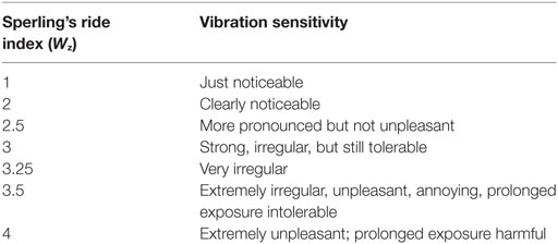
Table 2. Evaluation of ride comfort according to Sperling’s ride index (Narayanamoorthy et al., 2008).
Other standards for evaluating ride comfort do exist such as UIC513, BS 6841, and ENV-12999 (Dumitriu, 2013); however, they do not seem to be employed in any of the papers that have been reviewed and appear to have been made obsolete by BS ISO2631-1:1997. Karakasis et al. (2005) state that the BS ISO 2631-1:1997 is the most precise method but also argue that in certain circumstances where two or more situations need to be compared, the Sperling’s ride index can be more convenient and appropriate. Darlton and Marinov (2015) agree with this and state that due to the Sperling’s ride index need for each direction to be determined separately, it is less accurate compared to BS ISO 2631-1:1997. Darlton and Marinov (2015) also argue that the Sperling’s ride index is easier to read and understand. All of the authors seem to agree that BS ISO 2631-1:1997 is far superior to the Sperling’s ride index in the accuracy and quality of results it produces. However, Sperling’s ride index method still sees use since the results are easier to read and understand. Using both methods is the choice all of the authors made, and it gives an accurate prediction of the ride comfort as well as a number that can easily be compared between different situations.
It is important to note that the values obtained from the BS ISO 2631-1:1997 and Sperling’s ride index must agree with the subjective ratings, otherwise they are not fulfilling their purpose of predicting ride comfort. This point is heavily discussed in Strandemar (2005), and the paper presents evidence that using the methods suggested in BS ISO 2631-1:1997 have shown strong correlation to subjective rating and have proven to be successful in measuring the ride comfort. However, a study done in Sweden by Narayanamoorthy et al. (2008) argues that both the BS ISO 2631-1:1997 method and Sperling’s ride index are inadequate when it comes to measuring the effect of vibrations on the comfort of passengers performing sedentary activities, specifically the use of laptops on trains. The study did not mention the sample size; however, the argument is supported by the findings of Nakagawa and Suzuki (2005), which also indicate that passengers using laptops are more sensitive to discomfort caused by vibration. This mainly affects train journeys which durations are around 1 h or longer as most passengers who did not intend travel for less than an hour did not expect to use their laptops (Nakagawa and Suzuki, 2005; Narayanamoorthy et al., 2008). One can imply from this that passengers traveling only for short duration journeys are not as sensitive to discomfort caused by vibrations as passengers traveling longer journeys, who might expect to be able to read, write or use laptops. As improvements to ride comfort continue, more sensitive methods and limits might be required to evaluate ride comfort.
It is important to keep in mind that passengers in different parts of the world might perceive ride comfort differently, and so a study done in Sweden might not have as much relevance in other parts of the world. This must be considered when comparing subjective measurements of ride comfort between different parts of the world.
Mechanical Causes of Ride Discomfort
Understanding how the track and train characteristics affect the motions of the train is important to interpreting the data regarding ride comfort. Vibrations in trains can be caused by welding and rolling defects, rail joints, poor track alignments, various defects/roughness in the track or wheel surfaces, etc. (BS ISO 2631-4:2001; Karakasis et al., 2005; Lauriks et al., 2003). The vibrations can be divided into six components consisting of translational vibration in the x, y, and z-axis and rotational vibration in the x, y, and z-axis (British Standards Institution, 1997b, BS ISO5805:1997; British Standards Institution, 2001, BS ISO 2631-4:2001; Karakasis et al., 2005; Suzuki, 1998). The vibrations experienced inside the train are partially dampened because of the suspension between the bogie and the carriage, etc. (Kargarnovin et al., 2005). The traveling speed of the train can also magnify the amplitude of the vibrations the faster the train goes (Esveld and Kok, 1998; Youcef et al., 2013). Further sections will briefly discuss how different types of track might affect ride comfort.
Rail Bridges
Railway bridges allow trains to cross over an obstacle and are very common all around the world; however, crossing over them can have adverse effects on ride comfort. Kargarnovin et al. (2005) show that in the train–track–bridge interaction, the wheel–track roughness is the dominant factor causing ride discomfort when crossing a rail bridge. However, according to data obtained from experiments, the wheel–track roughness becomes less dominant compared to the train–bridge interaction as the speed of the train crossing the bridge increases (Kargarnovin et al., 2005; Youcef et al., 2013). This means that when traveling at low speeds the impact on ride comfort from the bridge itself is quite low, rather the condition of the track has the largest impact on ride comfort. As the speed increases the act of traversing the bridge, and the consequent change in foundation strength has an increasing impact on ride comfort. Kargarnovin et al. also states that ride comfort linearly increases with the stiffness of the bridge supports.
Motions induced by the train unto the bridge can cause discomfort among passengers in the form of vertical and rotational acceleration (roll) (Youcef et al., 2013). The sudden change in the stiffness of the track when the train crosses the bridge can cause jerk and other vibrations detrimental to ride comfort (Youcef et al., 2013; Kaewunruen, 2014a). Kaewunruen (2014a) and Kargarnovin et al. (2005) indicate that enhancing the stiffness of the ballast near bridge ends slightly improves the ride comfort in those zones. The motions of the train passing over the bridge can also cause excitation of the bridge, which in turn also has an effect on the ride comfort of the passengers (Youcef et al., 2013).
Turnouts (Switches and Crossings)
A railway turnout (also called switches and crossings) is a type of track allowing trains to switch from one track to another. Passing a turnout induces motions in the train due to the rail track discontinuity in the turnout (BS ISO 2631-4:2001; Ren et al., 2005). Kaewunruen (2014b) show a large increase in vertical vibrations when passing a turnout. A sizeable difference in the amplitude of the vibrations, before and after action was taken to improve the condition of a deteriorated turnout, can also be observed in Kaewunruen (2014b). After the turnout was mended, a significant increase in ride comfort was observed. There are also substantial lateral vibrations associated with turnouts (Ren et al., 2005). Turnouts poorly aligned or in poor condition can cause significant vertical and lateral vibrations and may even cause derailment of the train (BS ISO 2631-4:2001; Ren et al., 2005).
Turns and Curves
When the train turns, there is an increase in rotational vibration (roll) (BS ISO 2631-4:2001; Orvnäs, 2011), this vibration is generally reduced due to the presence of cants (where one half of the track is superelevated), which enable trains to maintain higher speeds while traversing the curve. There is also an increase in lateral vibrations causing passenger to experience swaying when a train passes a curve (BS ISO 2631-4:2001; Orvnäs, 2011), which might have a negative impact on ride comfort. Sudden jerk might also be experienced due to changes in the curve radii (BS ISO 2631-4:2001; Lauriks et al., 2003).
Past Developments of Smartphones’ Applications for Measuring Ride Quality
In recent years, the potential for the use of smartphones in enabling passengers to measure ride comfort has drawn a great deal of interest, and a few studies have been done using smartphones instead of traditional accelerometers. One project in Sweden, called Roadroid (Forslöf, 2012; Forslöf and Jones, 2014), investigated the use of smartphones in determining the conditions of roads and the ride comfort associated with it. Forslöf (2012) found that there are big differences between different smartphones in terms of the quality and sampling frequency of data, making it sometimes problematic to compare data between them. Before using data from two different phones, data samples should be taken from the phones and compared to each other to observe the differences in sensitivity and sampling rate.
Based on field trials done by Forslöf, the smartphones were able to deliver usable data for the purpose of evaluating ride comfort on roads. Forslöf also mentions that this type of technology can open up opportunities in developing countries where there is a limited availability of advanced measuring equipment. Islam and Johnston (2013) (cited in Forslöf and Jones, 2014, p. 7) showed a correlation of up to 81% between laser measurements and the measurements from the smartphone; this could suggest that measurements from the smartphone is sufficient for measuring ride comfort on roads (Forslöf and Jones, 2014). However, there is no mention as to how the laser measurements were carried out.
It should be noted that the types of vibrations experienced onboard trains are different from the ones experienced in road vehicles, and the test results gained from road vehicles do not necessitate that similar results will be achieved from measurements taken in rail vehicles. George et al. (2013) studied the discomfort of standing passengers in trains, using smartphone accelerometers. Vibrational data were measured from phones and a stopwatch was used to allow subjects to report perceived discomfort. Using logistic regression analysis, a relationship between the subjective discomfort readings and the measured vibrations was established. The study achieved an accuracy of 80% in predicting discomfort based of the logistic regression analysis, which is encouraging for the use of smartphones in measuring ride comfort. However, it should be noted that the study only used three subjects as well as using software not designed for the purpose of measuring ride comfort.
Before using third-party software for purposes it is not intended for, it should be understood how the software processes the data and if the software alters it in any way by using noise reduction filter to make the data more presentable. Based upon what is written in George et al. (2013), no actions have been taken to ensure the integrity of the data from the app. From the page of the app that George et al. (2013) claim to have used, users have reported that advertisements and other visual processes cause lag in the data gathering (Mobile Tools, 2013), this is observable in the data presented in George et al. (2013) where there are visible gaps between certain measurements, potentially caused by the lags.
A study done in Newcastle (Darlton and Marinov, 2015) to evaluate the use of tilting technology in the “Tyne and Wear” metro also made use of smartphone accelerometers. The study made use of third-party software in the same manner as in George et al. (2013). The data were recorded by strapping the phone to the chest or thigh of a passenger, to better observe the trains effect on whole body vibration according to Darlton and Marinov (2015). This method might be considered questionable as the body itself dampen vibrations significantly depending on the individual and vibrations reaching the chest are even more dampened compared to vibrations in the thigh (Silva et al., 2011). Darlton and Marinov claim that 95% of all recorded vibrations were induced by train movements.
The studies done by Darlton and Marinov (2015) and George et al. (2013) make the presumption that a smartphone accelerometer is of sufficient quality to measure ride comfort aboard rail vehicles although no studies have been undertaken to support this. In fact, this literature review has found that the commonly used standards to evaluate ride comfort are BS ISO 2631-1:1997 standard and Sperling’s ride index. The development of any new method must be consistent with these indices. Therefore, it is crucial to develop a novel and innovative smartphone application that could enable passengers to evaluate their trips, which is compatible with accepted standard practice such as the BS ISO 2631-1:1997 standard and Sperling’s ride index.
Methodology
Developing the App
The application developed to measure ride quality was made in Google’s Android Studio Integrated Development Environment with the Android Software Development Kit (SDK). The Android SDK was chosen as the author owns a Nexus 4, which was already set up to work with Android Studio. This method of app development was chosen as there is an abundance of documentation available regarding the Android SDK, and there is no real benefit in using another method to develop the app.
Due to the size and low cost of accelerometers and gyroscopes in smartphones, the instruments are generally not as accurate as their more expensive counterparts (Sachs, 2010). The accelerometers and gyroscopes found in smartphones only measure on sensor change; therefore, there is no set sample rate for the smartphones instead it varies depending on how often the phone detects a change in the accelerometer. How often the phone can detect a change in the sensor depends on the quality of the sensor itself as well as how fast the processor of the phone is. To find the average sampling rates inherent to different phones, as described by Forslöf (2012), a function was developed in the app to give an indication of the different average sampling rates possible when starting the app. BS ISO 2631-4:2001 suggests using a coordinate system for rail vehicles as illustrated in Figure 1. Each axis is defined using the following references:
• z-axis: perpendicular to the floor.
• x-axis: along the direction of travel.
• y-axis: lateral at right angles to the direction of travel.
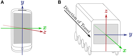
Figure 1. Comparison of the local coordinate system for a smartphone and the coordinate system of a train. (A) Coordinate system used by the Android sensor API (Google, 2015). (B) Coordinate system for a vehicle as proposed by BS ISO 2631-4:2001.
Figure 1A shows the default coordinate system used by the smartphone sensor systems. The device might be placed in different positions/orientations for the purpose of recording data, to avoid confusion and to ease analysis of the data the coordinate system of the phone will be translated to the coordinate system suggested in BS ISO 2631-4:2001.
Parameters to Be Recorded
The application has been programmed to record the following parameters:
• Time and date
• The translational and rotational accelerations in the x, y, and z axes.
• Type of instrument (i.e., accelerometer or gyroscope) to help separate the readings in MATLAB.
• GPS location to see which parts of the track is associated with certain vibrations.
These parameters are sufficient to achieve the aims and objectives of this project.
Field Testing
The field testing took place on the ninth of March 2016 in Long Marston, UK. A shunter had to be used in place of a locomotive for the experiment due to some unfortunate circumstances. The shunter could only travel up to 17 mph, and so all of the experiments were conducted on varying speeds between 5 and 17 mph. For the experiment, the shunter passed back and forth on the section of track highlighted in Figure 2. The length the shunter traveled was approximately 600 m; however, this varied from pass to pass due to the needs of other researchers on site.
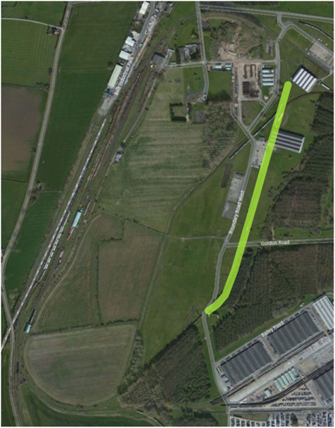
Figure 2. A map of Long Marston with the section of track that was used highlighted in yellow.
Two phones were acquired for field testing, a Nexus 4 and a HTC Sense as well as a PCB accelerometer. These phones were chosen as they were what was readily available. The phones were placed at the end of the carriage along with the accelerometer where the risk of people inadvertently bumping into them was minimized. The phones were placed on a thin high-friction rubber pad to prevent any movement, so that there would no relative motion between the carriage and the phones. The rubber pads were deemed the cheapest non-destructive way of holding the phones in place, which is they were chosen for the task. Unfortunately, the magnetic base that was meant to be used with the accelerometer was not available, and so the accelerometer was also secured on the rubber pad due to a lack of other alternatives, which can be seen in Figure 3. The data collection on the phones was started manually by tapping the start button in the app, and data from the accelerometer were recorded on a laptop.
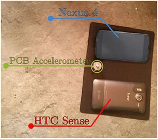
Figure 3. The placement of the two phones and the accelerometer before any wires were connected.
Analysis Using MATLAB and an ANN
The data were resampled to 35 Hz in MATLAB; this was done to make it possible to synchronize the data more easily as well as preparing it for analysis in the ANN. Thirty-five hertz was the lowest average sampling rate during the experiment, and so to reduce the risk of introducing any errors, it was chosen as the resampling rate for all of the data. The data from the two phones were then used as input data for the ANN, while the accelerometer data were put as the output data and so the ANN was trained. The whole process can be seen in Figure 4. The ANN model was then used to calculate the regression and get the coefficient of determination.
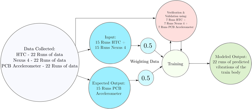
Figure 4. Diagram showing the details of the ANN analysis process.
Ride comfort indices were also produced in MATLAB following the equations discussed in Sections “Ride Comfort” and “Mechanical Causes of Ride Discomfort.” The ride comfort indices can be calculated in accordance with BS ISO 2631-1:1997 standard and Sperling’s ride index. The validation of the outcomes has been presented elsewhere. Excellent agreement (less than 3% error) is found in our ANN model (50% weighting) between trained and untrained data (prediction and measurement).
Results and Discussion
Results from the ANN show that the measurements from the phones and the accelerometer have a R2 value around 85% as shown in Figure 5. A 100% value would indicate a perfect fit, whereas a 0% value would indicate that there is no relationship between the two measurements. The reason that the coefficient of determination is not closer to 100% is most likely due to human errors introduced during the experiment, such as people coming into contact with the accelerometer equipment.
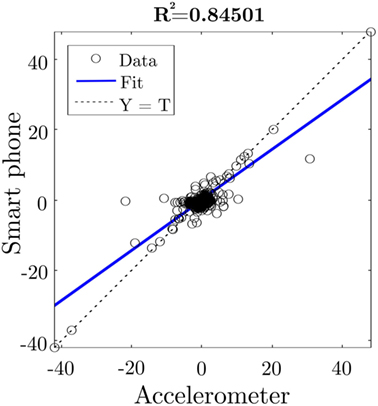
Figure 5. Regression analysis done by MATLAB’s ANN.
Visual inspection of the collected data in Figures 5 and 6 confirms that the three devices all show the same vibrations. All of the data that were recorded is shown in Figure 6. Although the data in Figure 6 are presented as a continuous stream of data, it was actually not. We have observed several gaps in the time axis, which are not clearly shown. In general, Figure 6 shows the differences in the sensitivity, noise level, etc. between the three devices due to the differences in the type of accelerometers and support conditions. It can be also a good visual representation of all the errors that have been introduced into the accelerometer data. Every time the PCB chart violently spikes and goes beyond the y-axis limits, it means that something or someone had physical contact with either the accelerometer itself or the cable attached to it.
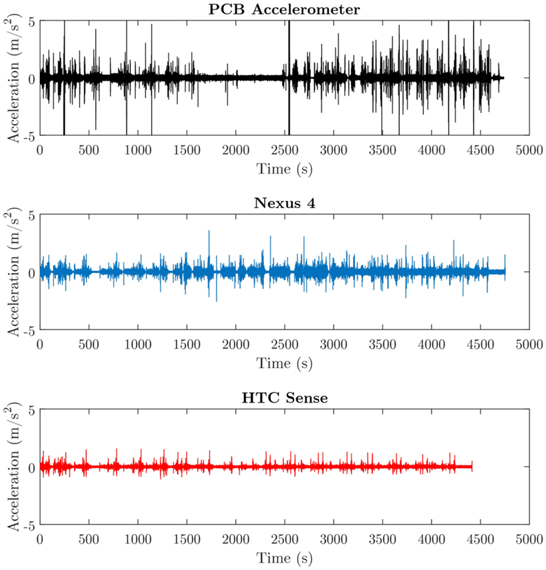
Figure 6. All of the data collected in Long Marston (not synchronized with each other), recorded at 17 mph.
The lack of major vibrations in the PCB chart between 1,500 and 2,500 s was caused by the cable coiling and coming into contact with another piece of electric equipment effectively preventing any meaningful data from being recorded during that time. The HTC Sense chart is shorter than the others because the phone itself crashed on two occasions during the field trial due to unknown reasons.
In Figure 7, the differences in measurements from the accelerometer and the two phones are observable. The measurement starts as the shunter just started moving around the 60 s mark the shunter starts braking and goes to a full stop 15 s later. It then starts moving again at around the 100 s mark. The accelerometer has a lot less noise, and the spikes that occur from the air brakes being used are clearly visible. The HTC Sense struggles to record many of the greater vibration, probably due to possessing an older and lower quality accelerometer, but also possibly because it does not have the processing power to keep up with the speed at which the measurements are being recorded.
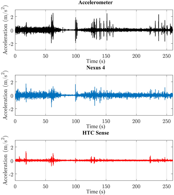
Figure 7. A 4-min and 20-s sample of the data that were collected in Long Marston, recorded at 17 mph.
Two different methods were used to calculate the ride comfort, BS ISO 2631-1:1997 and Sperling’s ride index; these can be seen in Figures 8 and 9. Excellent agreement can be observed using the British Standard, while very good prediction (peak picking) can also be found using Sperling’s index.
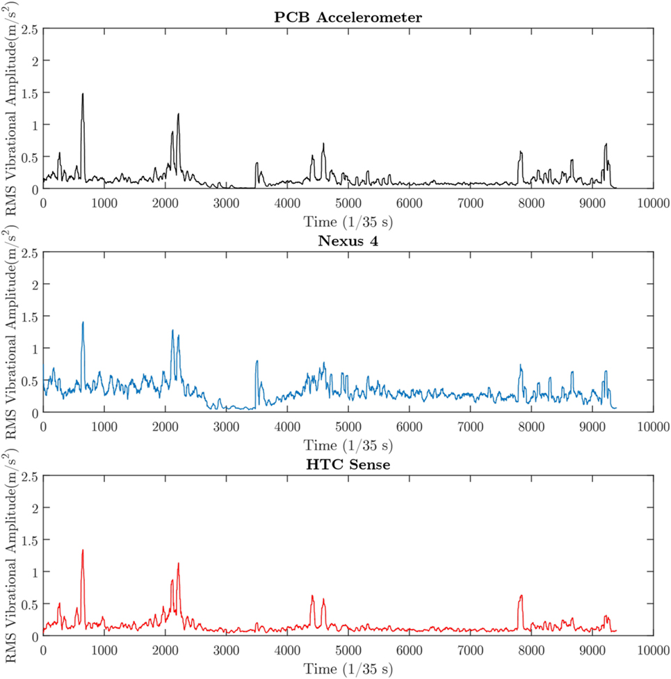
Figure 8. BS ISO 2631-1:1997 ride comfort for the 4-min sample.
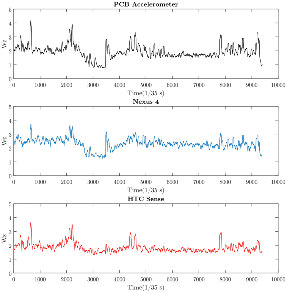
Figure 9. Sperling ride index for the 4-min sample.
Figure 10 shows what percentage of the journey would be considered comfortable or uncomfortable according to Tables 1 and 2. Most of the spikes in vibration amplitude were caused due to the driver of the shunter being quite inexperienced with the vehicle and using the air brakes a lot to regulate the speed. From Figures 7 and 8, it is quite clear that both phones give a very good representation of ride comfort when compared to the PCB accelerometer. Many of the figures indicate that there are some issues with the noise levels of the phones, especially the Nexus 4, while the HTC Sense might have some issues with its sensitivity.
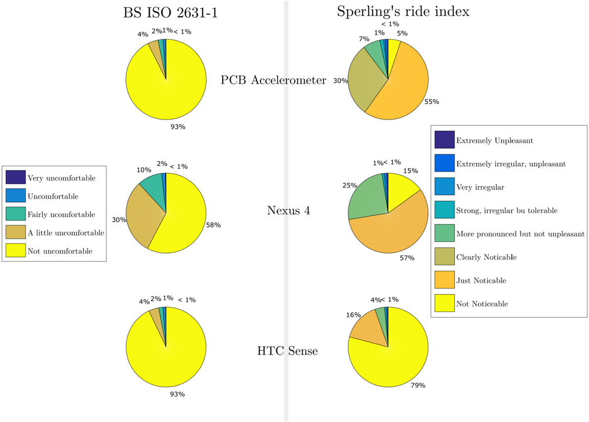
Figure 10. Pie charts showing the percentage of different comfort zones in a 4-min journey.
Power spectral density charts were produced and compared, which can be seen in Figure 11. The spectral charts can be used to understand where many of the vibrations are coming from as generally actions in the lower frequency domain relate to the wheel–track interaction, while actions in the higher frequency domain mainly concern the train itself (Oostermeijer and Kok, 2000; Schulte-Werning et al., 2007). Changes to the profile of the spectral chart can indicate changes to the condition of either the track or train. Using the app to create a record of the spectral profile of the train/track could potentially be used to know what condition the train/track is in.
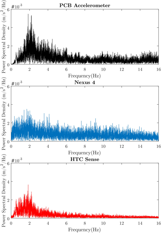
Figure 11. Power spectral density charts for each device made using fast Fourier transformation.
Discussion
Based on the results shown in Section “Past Developments of Smartphones’ Applications for Measuring Ride Quality,” the accelerometers in the smartphones seem to be able to measure ride comfort at a level comparable to that of a more sophisticated accelerometer. As was mentioned in Section “Past Developments of Smartphones’ Applications for Measuring Ride Quality,” the phones did have a different sampling rate and sensitivity as can be seen in Figure 6 when comparing data for the Nexus 4 to the HTC Sense. It should also be noted that both phones that were used, were relatively old. The Nexus 4 was almost 4 years old, whereas the HTC Sense was around 5 years old. Mobile technology develops at a high rate, and the smartphones of today and in the future will be equipped with higher quality accelerometers compared to the ones used in this experiment. Based on the results of this project, the technology used in modern smartphones is more than enough to measure ride comfort aboard trains.
However, it is not the quality of the sensors inside the phones that will hinder this type of technology from being implemented. Roadroid in Sweden is very successful because the application itself is part of a GPS program. Many drivers in Sweden use their phones for their GPS functionality and so getting people to use roadroid is exceedingly simple, just package it with the most popular GPS software. However, for the app that was developed for this project, it would much more difficult to get passengers to use it. There exists no reason to start up a specific app aboard a train and let it lay relatively still while collecting data. The greatest challenge in employ this type of technology is to make passengers themselves implement it in their daily lives. For roadroid, it was relatively simple as drivers were already implementing the use of phone GPS in their lives. For this app to be successful, there needs to be an incentive for passengers to use and implement it.
Providing an incentive could be done in a variety of ways, the app could be packaged with another app popularly used onboard trains if such an app exists. Rail companies could provide Wi-Fi onboard their trains while making it so that the app has to be running in order for the passenger to access the Wi-Fi network. Another idea might see that railway companies provide discounts to passengers who voluntarily use the app and collect valuable data. Perhaps, passengers themselves are curious about the ride comfort and end up implementing the app in their travels on their own. At this stage of the technology, how it will be implemented is mostly speculation. Unfortunately, during the field trials, the carriage only traveled on straight track, and so it was not possible to collect any data on how well the phones can measure swaying and other vibrations that are not in the z-axis (perpendicular to the floor).
Error Sources
Due to the HTC Sense being an older phone, the processor was not very powerful and so the sample rate varied quite a lot, dropping down to as low as 18 Hz at certain point in the data collecting. It is entirely possible for it to have missed ride comfort significant vibrations as the phone is forced to buffer the recording of the data due to the lack of processing power. Designing the application in such a way that it is more efficient in the use of processing power might be a way to mitigate this type of problem in the future. Due to the lack of a magnetic base for the accelerometer, the only thing preventing it from moving was the rubber pads it was sitting on; the device was not very secure at all and at one point in the data collection toppled over from the strong vibration caused by the shunter’s air brakes. It should be noted that the HTC Sense has a broken screen due to being exposed heavy pressure; it is unknown how this has impacted on the sensors. The Nexus 4 has had its screen replaced on two separate occasions, once due to scratches caused by sand and another time due to falling, shattering the screen. Both times the screen was replaced by an amateur, and therefore, the instruments on the phone may or may not have suffered. There were many other researchers onboard the carriage, and due to the lack of time, it was very hectic, and even though the accelerometer and the phones were placed out of the way as possible, people may have stepped near the phones or inadvertently touched the accelerometer or its wiring, introducing errors to the data.
Conclusion and Recommendation
In this study, we have investigated how well the accelerometers inside smartphones could measure ride comfort compared with a more sophisticated accelerometer. Although the phones show some inconsistency in being able to properly detect lower levels of discomfort, they show similarities when it comes to finding more uncomfortable levels of vibrations. After reviewing the results of the field trials, it is evident that there is merit in using smartphones for the purpose of measuring ride comfort aboard trains.
Every year more advanced accelerometers are being used in phones, in the future smartphones will be able measure ride comfort with even more accuracy than they currently can. The inherent differences in the different phones sampling rate and quality of data could be seen in Figure 5. These differences between the phones can make it difficult to standardize the accuracy of the ride comfort that the application records. A database that keeps track of the inherent differences between the phones would need to be made if this app is to be put to use.
Due to there being many possible error sources during the field testing of the developed app, it is recommended that more testing be done to get less error-riddled data. Testing should preferably be done with a three-dimensional accelerometer to better test the phones ability to measure ride comfort in curves and turnouts. Correlating the measured vibrations with laser measurements of track could give a better understanding of the potential use of smartphones to determine the condition of the tracks/trains. Newer phones should be used as if and when this technology gets implemented the phones that are new at the time of development will be the standard in the future.
Based on our market research, we found that it is highly likely that passengers will install the app to better understand the ride quality. Adding a functionality to the app allowing passengers to give feedbacks on subjective causes of discomfort in trains such as smells, temperature, etc. could help rail companies improve conditions onboard the train. The extension can attract crowdsourcing data that could truly improve customer experiences.
Author Contributions
AA and SK developed the idea; AA developed crowdsourcing platform and ANN server; AA and SK verified data and wrote the paper.
Conflict of Interest Statement
The authors declare that the research was conducted in the absence of any commercial or financial relationships that could be construed as a potential conflict of interest.
Acknowledgments
The authors deeply appreciated technical support and constructive advice during field measurement campaigns from Drs. Edward Steward, Mayorkinos Papaelias, Graeme Yeo, and Sarah Yeo. In addition, they are grateful to both the reviewers for their constructive comments.
Funding
The authors are very grateful for the financial support from European Commission for H2020-MSCA-RISE Project No. 691135 “RISEN: Rail Infrastructure Systems Engineering Network,” which enables a global research network that tackles the grand challenge in railway infrastructure resilience and advanced sensing under extreme conditions (www.risen2rail.eu). This project is also partly sponsored by H2020-S2R Project No. 730849 “S-CODE: Switch and Crossing Optimal Design and Evaluation.”
References
British Standards Institution. (1997a). Mechanical Vibration and Shock – Evaluation of Human Exposure to Whole Body Vibration – Part 1: General Requirements. London: BSI. (BS ISO 2631-1).
British Standards Institution. (1997b). Mechanical Vibration and Shock – Human Exposure – Vocabulary. London: BSI. (BS ISO 5805).
British Standards Institution. (2001). Mechanical Vibration and Shock – Evaluation of Human Exposure to Whole Body Vibration – Part 4: Guidelines for the Evaluation of the Effects of Vibration and Rotational Motion on Passenger and Crew Comfort in Fixed-Guideway Transport Systems. London: BSI. (BS ISO2631-4).
British Standards Institution. (2009). Mechanical Vibration, Shock and Condition Monitoring – Vocabulary. London: BSI. (BS ISO 2041).
Darlton, A. O., and Marinov, M. (2015). Suitability of tilting technology to the tyne and wear metro system. Urban Rail Transit 1, 47–68. doi: 10.1007/s40864-015-0007-8
Dumitriu, M. (2013). Evaluation of the comfort index in railway vehicles depending on the vertical suspension. Ann. Fac. Eng. Hunedoara 11, 23–32.
Esveld, C., and Kok, A. W. M. (1998). Interaction between moving vehicles and railway track at high speed. Rail Eng. Int. 27, 14–16.
Forslöf, L. (2012). Roadroid–Smartphone Road Quality Monitoring. Available at: http://hojja.se/common/References/Roadroid%20Final%20Paper%20ITS%20World%20Congress%20Vienna%202012.pdf
Forslöf, L., and Jones, H. (2014). Roadroid Continuous Road Condition Monitoring with Smart Phones. Available at: http://roadroid.com/common/References/SARF-IRF%20paper.v5.pdf
Förstberg, J. (2000). Ride Comfort and Motion Sickness in Tilting Trains. Available at: www.diva-portal.org/smash/get/diva2:8728/FULLTEXT01.pdf
George, T. K., Gadhia, H. M., Sukumar, R. S. O., and Cabibihan, J.-J. (2013). “Sensing discomfort of standing passengers in public rail transportation systems using a smart phone,” in 10th IEEE International Conference on Control and Automation (ICCA) 12–14 June 2013 (Hangzhou, China), 1509–1513.
Google. (2015). Coordinate System (Relative to a Device) That’s Used by the Sensor API. Available at: https://developer.android.com/guide/topics/sensors/sensors_overview.html
Islam, T., and Johnston, M. (2013). Using Cell-Phones to Monitor Road Roughness. Auckland, New Zealand: Department of Civil and Environmental Engineering, University of Auckland.
Kaewunruen, S. (2014a). Impact damage mechanism and mitigation by ballast bonding at railway bridge ends. Int. J. Railw. Technol. 3, 1–22. doi:10.4203/ijrt.3.4.1
Kaewunruen, S. (2014b). Monitoring structural deterioration of railway turnout systems via dynamic wheel/rail interaction. Case Stud. Nondestr. Test. Eval. 1, 19–24. doi:10.1016/j.csndt.2014.03.004
Karakasis, K., Skarlatos, D., and Zakinthinos, T. (2005). A factorial analysis for the determination of an optimal train speed with a desired ride comfort. Appl. Acoust. 66, 1121–1134. doi:10.1016/j.apacoust.2005.02.006
Kargarnovin, M., Younesian, D., Thompson, D., and Jones, C. (2005). Ride comfort of high-speed trains travelling over railway bridges. Veh. Syst. Dyn. 43, 173–197. doi:10.1080/00423110512331335111
Lauriks, G., Evans, J., Förstberg, J., Balli, M., and Barron de Angoiti, I. (2003). UIC Comfort Tests. Available at: http://vti.diva-portal.org/smash/get/diva2:670177/FULLTEXT01.pdf
Mobile Tools. (2013). Vibration Monitoring [Android App]. Available at: https://play.google.com/store/apps/details?id=com.lul.vibration.monitoring
Nakagawa, C., and Suzuki, H. (2005). Effects of train vibrations on passenger pc use. Q. Rep. RTRI 46, 200–205. doi:10.2219/rtriqr.46.200
Narayanamoorthy, R., Saran, V., Goel, V., Harsha, S., Khan, S., and Berg, M. (2008). “Determination of activity comfort in swedish passenger trains,” in Proceedings of 8th World Congress on Railway Research (WCRR 2008) (Seoul, South Korea), 18–22.
Oostermeijer, K., and Kok, A. (2000). Dynamic behaviour of railway superstructures. HERON 45, 25–34.
Orvnäs, A. (2011). On Active Secondary Suspension in Rail Vehicles to Improve Ride Comfort. Available at: www.diva-portal.org/smash/get/diva2:460526/FULLTEXT01.pdf
Ren, Z., Sun, S., and Zhai, W. (2005). Study on lateral dynamic characteristics of vehicle/turnout system. Veh. Syst. Dyn. 43, 285–303. doi:10.1080/00423110500083262
Sachs, D. (2010). Sensor Fusion on Android Devices: A Revolution in Motion Processing. Google Tech Talks. Available at: https://youtu.be/C7JQ7Rpwn2k
Schulte-Werning, B., Thompson, D., Gautier, P., Hanson, C., Hemsworth, B., Nelson, J., et al. (2007). “Noise and vibration mitigation for rail transportation, systems,” in Proceedings of the 9th International Workshop on Railway Noise (Munich, Germany).
Silva, H., Lourenco, A., Tomas, R., Lee, V., and Going, S. (2011). “Accelerometry-based study of body vibration dampening during whole-body vibration training,” in IEEE International Workshop on Medical Measurements and Applications Proceedings (MeMeA) 30-31 May 2011 (Bari, Italy), 98–102.
Sperling, E., and Betzhold, C. (1956). Beitrag zur beurteilung des fahrkomforts in schienenfahrzeugen, Vol. 80. Dresden, Germany: Glasers Annalen, 314–320.
Strandemar, K. (2005). On Objective Measures for Ride Comfort Evaluation. Available at: www.diva-portal.org/smash/get/diva2:14199/FULLTEXT01.pdf
Suzuki, H. (1998). Research trends on riding comfort evaluation in japan. Proc. Inst. Mech. Eng. F J. Rail Rapid Transit 212, 61–72. doi:10.1243/0954409981530689
Keywords: railway infrastructure, ride quality, operations monitoring, artificial neural networks, mobile application
Citation: Azzoug A and Kaewunruen S (2017) RideComfort: A Development of Crowdsourcing Smartphones in Measuring Train Ride Quality. Front. Built Environ. 3:3. doi: 10.3389/fbuil.2017.00003
Received: 18 October 2016; Accepted: 11 January 2017;
Published: 03 February 2017
Edited by:
Chris Hendrickson, Carnegie Mellon University, USAReviewed by:
Rasa Ušpalytė-Vitkūnienė, Vilnius Gediminas Technical University, LithuaniaCheul Kyu Lee, Korea Railroad Research Institute, South Korea
Copyright: © 2017 Azzoug and Kaewunruen. This is an open-access article distributed under the terms of the Creative Commons Attribution License (CC BY). The use, distribution or reproduction in other forums is permitted, provided the original author(s) or licensor are credited and that the original publication in this journal is cited, in accordance with accepted academic practice. No use, distribution or reproduction is permitted which does not comply with these terms.
*Correspondence: Sakdirat Kaewunruen, sakdirat@hotmail.com, s.kaewunruen@bham.ac.uk