Lifecycle Assessments of Railway Bridge Transitions Exposed to Extreme Climate Events
 Sadudee Setsobhonkul
 Sakdirat Kaewunruen
 Joseph M. Sussman
- 1TEAM Consulting Engineering and Management Co., Ltd., Bangkok, Thailand
- 2Department of Civil Engineering, University of Birmingham, Birmingham, United Kingdom
- 3Department of Civil and Environmental Engineering, Massachusetts Institute of Technology, Cambridge, MA, United States
Railway track components located at bridge transition zones or approach areas suffer from impact load and vibrations caused by abrupt changes in track stiffness on the bridge and the subgrade. The numerous strategies that can be used to mitigate these abrupt track stiffness changes rely on one of two concepts. The first concept is that of providing a gradual stiffness change, and the second is that of equalizing the track stiffness. A number of such mitigation methods have been developed and implemented over recent decades. Construction activities associated with these methods require various materials, processes, and uses of time, costs, and carbon emissions. In this study, eight of the most common techniques for railway bridge transition mitigation, including under ballast mats (UBMs), soft baseplates, under sleeper pads (USPs), rail pads, embankment treatments, transition slabs, ballast bonding, and wide sleepers, are compared. This study benchmarks the costs and carbon emissions of these eight mitigation techniques over the 50-year lifespan of a railway system subject to identical probabilities of four environmental scenarios: a control case, extremely high temperatures, extremely low temperatures, and flash flooding. This unprecedented study systemically investigates the effectiveness of the mitigation methods while considering the effects of 30 and 100 m bridge span lengths. Our results indicate that railway engineers should adopt different mitigation methods for different scenarios. The soft baseplate is the most appropriate method for a short-span bridge in the control case and the case of flash flooding, while ballast bonding is better for long-span railway bridges. Embankment treatment is recommended for both high- and low-extreme temperatures. However, its applicability is limited when the differential track stiffness is extremely high. Hence, alternatives that are 5–25% more expensive are proposed in parallel. The alternative methods include ballast bonding, and the USP and UMB methods, the latter two of which are designed for different climate scenarios. These recommendations translate novel insights from the systems thinking approach into practice and will benefit the railway industry significantly over the long term, enhancing both economic and environmental sustainability.
Introduction
Recent, rapid expansion of railway systems (e.g., metro, urban, and suburban rails, freight, etc.) has occurred globally. In order to provide an efficient and sustainable railway service suitable for local geographies and geometries, it is necessary to design and adopt railway assets and infrastructure such that they work in harmony with local specifications and constraints (e.g., underground tunneling, overpass/underpass bridges, rock cutting, etc.). To cope with diverse geographies such as mountains, fields, and rivers, special infrastructure such as railway bridges and tunnels has been designed to provide economic solutions for specific railway lines. Efficient and sustainable railway services can be developed via optimized design and use of infrastructure. This yields valuable benefits with low economic and environmental costs. On the other hand, various types of infrastructure can cause problems that require specific maintenance regimes (Kaewunruen et al., 2015, 2016a,b). Modern railways use two common track systems: ballasted tracks and slab tracks. Both types of tracks may be connected to each other within the same route. The transition zone between ballasted and slab tracks has long been a maintenance priority since differential settlement can be observed due to rapid ballast deterioration in transition zones (Kaewunruen, 2014a,b,c, 2017). Higher-magnitude impact loads caused by train–track interactions in zones with stiffness differences increase wear rates, fatigue thresholds, and differential track settlement and also reduce passenger comfort. The transition zone between tracks on the embankment substructure and those on the bridge is commonly referred to as the “bridge transition.” Bridge transitions exhibit larger stiffness differences than other types of transition zones and thus require four to eight times more maintenance than ordinary tracks (José and Varandas, 2011; Tschumi, 2012). A typical bridge transition approach area is illustrated in Figure 1.
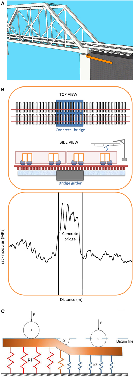
Figure 1. Track modulus and its interaction with railway system. (A) bridge end area; (B) change in track modulus; (C) change in track stiffness at transition areas (k1 is bridge stiffness; k2 is track stiffness; alpha is the relative dip angle).
At the bridge ends, the differential track stiffness can impart intense vibrations and dynamic impact forces to both the train bogies and the rails. These detrimental forces typically result when no improvements are applied to a track with 20 mm of irregular variation (Kang et al., 2008). Thus, a transition zone must be designed to decrease the contact forces and vibrations experienced by the tracks and trains. Appropriate transition zones protect the infrastructure from large impact forces and excessive vertical rail deflection. There are two types of track stiffness difference mitigation methods for continuous rails supported by various types of infrastructure (e.g., bedrock, soil foundations, bridge viaducts, etc.). Transition zone stiffness moderation is way of coping with different types of infrastructure that intrinsically yield different track stiffnesses (Sañudo et al., 2016).
Our critical literature review revealed that Lei and Zhang analyzed the dynamic behavior during track transitions using a finite element approach (Lei and Zhang, 2010). They found that abrupt stiffness changes can cause considerable vertical rail vibration acceleration. The study identified the dominant influences as train speed, subgrade stiffness, track transition irregularity, and angular irregularity during vehicle acceleration, which arises from vehicle suspension systems. The peak contact force can be minimized when the vertical rail deflection changes gradually.
The problems that can arise in transition zones are typically prioritized. Prioritization is informed by three main issues discussed by Zhang:
(1) An abrupt change in the vertical stiffness of the track causes the wheel to experience an equally abrupt change in elevation because of the uneven track deflection.
(2) At-grade ballasted track (or when a track structure or transit guideway is installed directly on ground formation) may inherently settle more than ballasted track on a structure or direct-fixation track, creating a dip in the surface at the transition; this is especially true when the structure abutment is built on a deep pile foundation where the settlement is negligible.
(3) Settlement of at-grade tracks can be highly variable because of geotechnical issues affecting the subgrade performance such as low strength soils, deficient soil placement and compaction, poor drainage, and erosion (Lei and Zhang, 2010).
Thus, the transition zones must deal with the differential track stiffness and are also exposed to substructure condition variations and foundation consolidation along the railway line. These problems lead to the need for various mitigation solutions that fit various budget constraints, mitigation objectives, lifecycles, condition monitoring technologies, and site conditions.
Currently, there are two main transition zone design options (Kaewunruen, 2014a,b,c):
• Option 1: equalize the stiffnesses and rail deflections of the ballasted and slab tracks by moderating the resilience of the rail on the slab track or the ballasted track over the bridge. A sensible solution is to reduce the stiffnesses of both the slab track and the track over bridge to match the ballasted track stiffness by inserting softer elastic materials.
• Option 2: provide a gradual stiffness increase (or stiffness ramp) in the ballasted track to match the stiffness of the slab track or the ballasted track over the bridge.
From the various practical techniques that can be adopted to solve this problem, eight have been chosen for this comparative study. They are under ballast mats (UBMs), soft baseplates, rail pads, under sleeper pads (USPs), transition slabs, embankment treatments, ballast bonding, and wide sleepers. These methods are used widely across Europe, Australia, North America, and Asia. In order to identify the optimal systemic approach, both lifecycle cost and environmental carbon footprint were evaluated using a discount rate determined based on recommendations for governmental rail projects (Kaewunruen, 2014a,b,c). The resulting improved understanding of railway bridge transition zone lifecycle performance under various environmental conditions will help track engineers to apply, develop, and prioritize customized mitigation actions and methods that are suitable for their rail lines. The novel insights developed using this systems thinking approach will help to reduce long-term maintenance costs and hence carbon footprints from railway maintenance and operation activities.
Recent Research on Transition Zones
Moduli of Materials
A railway track can be composed of various materials such as wood, steel, concrete, subgrade rock, and resilience materials. The differences between these materials affect their mechanical properties, short- and long-term performance under various conditions, and elasticities. Elasticity differences can cause negative track stiffness effects and lead to unplanned transition zone maintenance problems. The moduli of timber sleepered, ballasted tracks should be around 28–35 MPa, depending on their ballast thicknesses. Moduli may range from 25 to 41 MPa for their concrete sleepered counterparts, while those of rail tracks over concrete bridges can reach approximately 55–85 MPa (Kaewunruen, 2014a,b,c; Kaewunruen et al., 2017).
Optimum Track Stiffness
Although the track stiffness can be reduced to cope with unwanted differentials, it should still be optimized. Low track stiffness can cause a larger differential track displacement, whereas excess track stiffness leads to a higher dynamic load and additional rail deterioration (Puzavac et al., 2012). The track stiffness should be controlled appropriately, otherwise the vertical track geometry deterioration rate (or “top deviation”), which affects the train ride quality (Azzoug and Kaewunruen, 2017), will increase. Several vertical track stiffness recommendations are already available:
• 80–130 kN/mm (RSSB, 2005),
• 70–80 kN/mm on high speed lines (Pita, 2002),
• and 70–80 kN/mm on freight-traffic lines (Sussmann, 2001).
In the UK, infrastructure should be designed based on a track stiffness value obtained using a falling weight reflectometer measurement method (Kim, 2016), as follows:
• 60 kN/mm for a mainline without reinforcement (NR Standard 039, 2005)
• and 60 kN/mm for a new track up to 100 mph and 100 kN/mm for new track above 100 mph (NR Standard 039, 2005).
However, the optimum track stiffness is a theoretical value derived from a model. It depends on a number of factors such as the subgrade, ballast, steel rail stiffness, construction workmanship, maintenance quality, train axle load, train speed, and operational and environmental conditions (Esveld, 2001; Kaewunruen, 2013, 2014a,b,c, 2017).
Transition Zone Mitigation Methods
A number of techniques can be used to either provide gradual track stiffness changes or reduce the stiffness of a track over a bridge in order to eliminate stiffness differences in the transition zone. Here are some of the more common techniques.
Rail Pads
Rail pad or soft under rail pad (URP) installation is often used to reduce the differential track stiffness instead of providing a gradual track stiffness change. This method uses relatively soft elastic materials to support the rail and increases the elasticity of the track over the bridge. Rail pads can also provide gradual track stiffness increases via strategic placement of pads with different stiffnesses to establish variable stiffness ramping along on the rail supports. However, engineers must consider the permissible axle load imposed on each component of the fastening system to prevent premature damage to the rail pad and other parts of the track. According to a study by Lund and Åswärdh (2014), rail pads are used to reduce track stiffnesses in the stiffer portion of the transition, and elastomeric pads can be placed at the rail seat between the rail and sleeper. For the best results, the pad stiffness should be equal to the track modulus, thus enabling gradual stiffness increases and decreases along the track. The pads can also be customized in accordance with damping requirements, which attenuate high-frequency impact loads (Nyström and Prokopov, 2011). The deflection of structural concrete in most ballastless tracks is negligible. With wood or composite sleeper decks, localized compression stress may provide the main contribution to the total rail deflection. Thus, it is important to consider the material stiffness when selecting and applying pads (Jenks, 2006; Kaewunruen, 2013).
The characteristics and topologies of rail pads are important to the adaptation of solutions to a particular railway system. The rail pad dimensions vary depending on whether a UIC 54 or UIC 60 rail type is used. The dimensions are usually 180 mm long—140 mm wide and 180 mm long—148 mm wide, respectively. These pads are often used to improve the load distribution, resulting in better ride quality and protecting the superstructure from wear and damage. In addition, the elastic rail pad provides electrical and signaling insulation (between track circuits) and is a good source of damping that reduces transmission of rail vibrations to sleepers. This also reduces cracking and wear rates of concrete sleepers and abutments (Miguel Sol-Sánchez, 2015).
The use of rail pads in transition zones has been studied and implemented in European countries such as Germany, Spain, and France, typically to reduce track stiffness. For example, French railways use 9.0 mm thick rail pads and 90 kN/mm of stiffness in order to reduce the global vertical stiffness. Research from Greek railways found that the use of stiff rail pads increased stresses on the sleepers, causing them to crack. Their results also show that replacing stiff rail pads (250 kN/mm) with more flexible ones (40 kN/mm) reduced the stresses transmitted to the sleepers by up to 20% with a ballasted track (Miguel Sol-Sánchez, 2015).
Soft Baseplate
A baseplate consists of rubber and steel components that form a rail-fastening system, which is placed at the rail seat. The rails are then fastened to the stiff rail pads via the baseplate using steel spring clips. The baseplate pad is acoustically important and separates the baseplate from supporting structures such as bridge components. The assembly is generally fixed to a bridge component via anchor bolts and anti-vibration coil springs (Peeling, 2012). Soft baseplates provide additional elasticity to the portion of the track over the bridge, making them very useful in reducing the differential stiffness. A study by Kaewunruen (2016) field monitored a transition zone between a steel bridge and a plain-ballasted track, revealing interesting insights into the use of special soft baseplates and fastening systems on a transom railway bridge. The soft baseplate method improved the isolation of vibrations that travel from the track to the bridge and the formation at the bridge transition. Field vibration measurements showed that no significant vibrations transfer from the rails to sleepers or from the sleepers to the ballast layer. Although bridge transition vibration isolation has improved significantly, geometry data from the “AK Car” track inspection vehicle shows that deterioration continues due to the remaining dynamic effects at the bridge transition, but at a slower rate than on a railway bridge without soft baseplates (Kaewunruen, 2016). In addition, soft baseplates provide a more maintainable and durable approach than URPs on bridges, in addition to offering more effective and longer infrastructure lifespans.
Under Ballast Mats
Under ballast mats are among the many techniques used to reduce dynamic load actions in transition zones. As with rail pads, UBMs are designed to moderate the stiffer portion of the track, especially with ballasted tracks installed directly over concrete bridges or viaducts. The UBM is an elastic mat (or elastic material) that is installed between the ballast and the substructure of a ballasted track. They can also be installed underneath the concrete slabs of slab tracks. In specific areas such as tunnels, bridges, elevated stations, deep cuttings, and switches, the UBM is essential because its elasticity is required to reduce the track stiffness. This technique can reduce stresses on component materials from dynamic loads, noise emissions, and structural vibrations (Miguel Sol-Sánchez, 2015). The various types of UBMs usually have thicknesses of 15–30 mm and horizontal dimensions that depend on the technique developed during construction. UBMs typically contain a single layer of polymeric material, but they can sometimes have two layers. The first layer distributes loads uniformly, and the second (elastic) layer dampens dynamic loads. Alternative composites are being developed from waste tires to reduce the cost of UBM manufacturing (Miguel Sol-Sánchez, 2015).
A previous study of dynamic axle loads on tracks with and without ballast mats (Auersch, 2006) focused on vibration reduction. The study used a finite element model of UIC 60 rails with concrete sleepers on a ballasted track. It evaluated the force transfer functions, vehicle–track resonance, and forces reduction at higher frequencies. The results showed that insertion of the elastic mat under the ballast shifts the vehicle–track resonance by 20–50 Hz. This approach reduced the dynamic forces considerably. The study also showed that the resonant frequency and force reduction of a ballast-mat track depend on its stiffness, as well as the masses of the track and wheelset (Auersch, 2006).
Under Sleeper Pads
Due to the various variations of track conditions along the transition zone, USPs are sometimes used to enable for smoother track stiffness transitions. Note that the vertical stiffness of a railway track can change very rapidly over just a few meters, and tracks are seldom built on homogeneous sub grades. Sub grade properties such as stiffness can change along the track. The track stiffness changes in a semi-random manner. Thus, USPs can minimize track stiffness variations and decrease maintenance requirements (Witt, 2008).
The USP is a resilient material that is typically installed between the ballast and sleepers in the transition zone. It is typically around 6–20 mm thick and typically consists of two types of material: one used to provide stiffness and damping, and another for protection (Witt, 2008). According to a study by Schilder (2013), USPs have been manufactured from polyurethane (PUR), rubber, and ethylene-vinyl acetate (EVA).
Four different processes can be used to establish strong bonds between USPs and sleepers (Schilder, 2013), including
• coating by spraying or painting onto hardened concrete,
• gluing to hardened concrete,
• direct placement onto unset concrete (during sleeper production), and
• placement onto unset concrete via an interlocking layer (e.g., extruded knobs, wire meshes, geo-membranes, or fine-grained gravel).
Under sleeper pads can be classified into four stiffness levels: stiff, medium stiff, soft, and very soft. Their static stiffnesses (Cstat) can range from less than 0.10 to 0.25 N/mm3. The different USP stiffnesses influence the outcomes of their applications. For example, soft USPs can reduce ground-borne vibrations but can cause negative effects in the transition zone.
Based on a numerical study by Witt (2008), a model was developed that evaluates track performance with three different USP stiffnesses and includes rails, rail pads, sleepers, and ballasts. The track stiffness at the transition zone varied from about 40 to 160 kN/mm. A train speed of 90 m/s was used, and the wheel load was assumed to be 10,000 kg. The maximum vertical contact force at the transition zone was reduced from approximately 33 kN to approximately 18 and 25 kN with soft and medium USPs, respectively. There was no significant change in the stiff USPs. However, the wheel–rail contact force was larger and occurred for longer when soft USPs were used. Hence, medium USPs may be best for the transition zone.
Under sleeper pads have positive effects other than the track stiffness moderation. Other benefits identified by Schilder (2013) include
• USPs can ballast thicknesses;
• USPs can reduce long pitch rail corrugation on small radius sections;
• USPs can reduce high-frequency vibrations and structure-borne noise;
• USPs are alternatives to under-ballast mats above 40–50 Hz;
• USPs can reduce track maintenance;
• The track quality remains stable over a longer period of time;
• USPs can lead to higher railway track economic values; and
• The benefits are greatest at smaller radii. An internal rate of 5% is reached at all traffic load levels.
Transition Slab
A transition slab (approach slab) is a reinforced concrete slab installed as a structural element within the track substructure to increase the track stiffness/modulus. Most transition slabs are concrete structures and either are designed with a taper that gradually increases the stiffness over an approach distance of about 6 m or are uniform in thickness but placed at an angle with a tapered ballast depth to achieve the same ramping effect [Transportation Technology Center, Inc. (TTCI), 2006]. The transition slab is one possible transition zone infrastructure solution that provides a gradual change in track stiffness and reduces the dynamic impacts on rails and train dynamics. Transition slabs can be used on both railway tracks and on roadways in a similar manner. At least three different stiffness zones are present after implementation of the transition slab: between the ballasted track and the slab, between the slab and one end of the bridge, and between the other end of the bridge and the slab. Stiffness differences should be minimized to increase the effectiveness of this method.
The American Railway Engineering and Maintenance-of-Way Association recommends transition slabs that are at least 6 m long and taper from a depth of 0.460 m at the structure end to 0.300 m at the at-grade end. General specifications for an approach slab design based on various tests were provided by Sharpe et al. and cited by [Transportation Technology Center, Inc. (TTCI), 2006]. This transition slab design calls for vertical adjustment of the rails on the direct-fixation bridge deck. In addition, the adjustable fasteners permit the rail on the ballasted side to be raised above the desired final elevation and settle (design tamping). Incorporating design-tamping capabilities improves the transition performance beyond that of a simple approach slab [Transportation Technology Center, Inc. (TTCI), 2006].
Ballast Bonding
The ballast bonding or ballast glue method improves the stabilization and dynamic behavior of railway tracks by tackling and changing the ballast behavior. In the transition zone, it serves to reduce ballast settlement and improve the ballast track stiffness to avoid abrupt changes. Lakušic et al. (2010) suggested that a ballast glue transition area (MC-Bauchemie Müller GmbH) can be enabled by stabilizing the ballast under the first four sleepers. This is done by applying ballast glue over the full width of ballast bed, and then changing the area treated with glue between groups of four sleepers to gradually moderate the track stiffness. This method is shown in Figure 2.
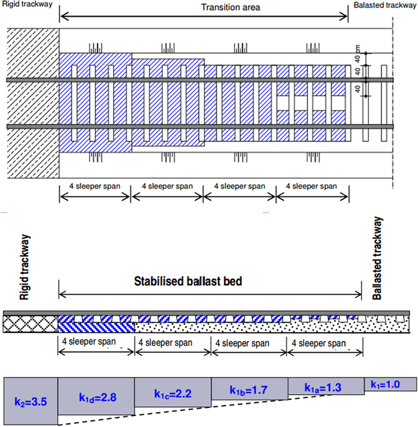
Figure 2. Gradual change in track stiffness on transition area (Lakušic et al., 2010).
A study of impact damage mechanisms and mitigation via ballast bonding at railway bridge ends has revealed that stabilization of the ballast bed using ballast bonding/glue bonds the corners and contact points of ballast gravel pieces. Adhesive implementation requires between 30 min and 3 h to establish the stiffness transition zones, depending on the type of adhesive used and the scale of work (Kaewunruen, 2014a,b,c). Studies in Europe have indicated some prerequisites related to track integrity that must be met when applying ballast glue:
• To improve the quality of the transition zone, the subgrade should be in good condition;
• mud-free tracks are required;
• a well-compacted ballast bed is preferable;
• the track geometry should be resurfaced and restored to the desired position prior to ballast bonding.
The study also suggested two methods of ballast stabilization as follows:
• Surface bonding: this method cosmetically prevents movement of ballast gravel in the surface area. A shallow ballast bond is applied to the ballast surface.
• Structural bonding: this method reinforces and enhances the mechanical properties (stiffness, stability, bearing capacity, etc.) throughout the ballast layer.
The research included extensive field measurements conducted by measuring the dynamic performances of both sides of the bridge using seven detection points on the HDPE pad, a ballast 250 mm in thickness, a subgrade 150 mm thick, and a compacted formation. Results showed that ballast bonding (MC-Bauchemie Müller GmbH) can suppress sleeper and ballast vibration at the bridge transition zone in the short to medium term. It also showed that the dynamic performance of substructure improves significantly. However, there were increases in high-frequency rolling (wheel–rail interface coupling) noise and low-frequency (0–10 Hz) track vibration. Overall, ballast bonding improves settlement, track surface geometry stability, and passenger comfort by increasing adhesion between aggregates. In economic terms, ballast bonding reduces overall maintenance costs and the frequency of maintenance by reducing tamping activities from four times per year to once every 3 years (Kaewunruen, 2014a,b,c).
Embankment Treatment
A study of the Sikån Bridge has demonstrated a bridge end improvement implemented by modifying the embankment structure (Fara, 2014). The embankment is generally an invisible portion of the railway substructure underneath the ballast. However, railway vibrations and dynamic impacts can affect it directly, causing damage to the embankment material. The embankment is normally affected by ground settlement and consolidates over time. The dynamic transition zone effects even expedite embankment settlement. Substructure settlement in turn causes the abrupt elevation changes that affect train ride quality and safety.
Methods of preventing differential settlement and providing gradual changes in track stiffness were studied and implemented in various countries using different forms and layers of embankment. German railway transition zones use three different types of backfill material with various elasticities and have provisions for drainage behind the abutment. The German transition zone design allows a 22.5 t maximum axle load with a maximum speed of 230 km/h. Swiss railways also use various types of backfill materials with geotextiles and specify the same maximum axle load and speed limit as the German system.
The French national railway uses five different backfill materials. They need to be compacted to a very high degree (95–100%). The top layer formation should be more than 5 m or equal to the abutment height (H). This transition zone allows 22.5 t of axle load with a maximum speed of 320 km/h. However, Fara’s study (Fara, 2014) stated that the transition embankment treatment might not be enough to prevent transition problems between foundation structures and substructures with different stiffness. This is because the foundation materials are often weaker than the structural materials, and physical constraints limit improvements in material stiffness. Other solutions such as ballast bonding and transition slabs may be used in combination with embankment treatment.
Effect of Temperature on Elastic Pads
Before implementation of rail pads, their static stiffnesses at temperatures between −40 and 70°C must be evaluated. Typically, a universal testing machine is equipped with a temperature control box to determine the influence of the temperature-dependent rail pad stiffness. This then influences vertical vehicle–track coupled vibrations. The static stiffnesses of these rail pads exhibit non-linear variations of temperature. The thermal responses of the pads depend largely on material characterization (e.g., natural, synthetic, recycled rubber, etc.). In general, the static stiffnesses of all three common types of rail pad are considerably sensitive to temperatures below 20°C, with chloroprene rubber (CR) rail pads being the most sensitive. Above 20°C, their static stiffnesses increase slightly with temperature; however, low-temperature (−40 to 70°C) effects on rail pad stiffness are more significant than higher temperature effects (20–70°C) (Wei et al., 2016).
Factors That Influence Bridge Transitions
For benchmarking purposes, the risks and probabilities of climate effects have been treated identically across all extreme scenarios. This study assumes that any localized effects are neutralized in order to enable fair and unbiased comparisons. In practice, local weather can be considered during design and planning.
Climate and Temperature Impacts
Climate change is a significant issue for every industry in the world. Global temperatures have risen sharply and continuously by an annual average of 0.5°C over the past 20 years (the zero line is the mean temperature from 1961 to 1990). Global warming and climate change have affected railways and other infrastructure (Binti Sa’adin et al., 2016a,b,c, 2017). They increase the renewal and wear rates of lubrication materials, as well as the possibility of track twisting and buckling. They have also affected the lifespans and performance of resilience materials used in railway systems (Wu and Kaewunruen, 2017).
Weather has important effects on railway systems. Conditions such as flooding, rainfall, heat, and snow can impair railway infrastructure and signaling systems. The variability associated with climate change creates problems for railway operators, nuisances for staff or passengers, and disruption of signaling systems, which directly harm infrastructure systems and can lead to accidents or derailment. Temperature increases in the transition zone and bridge transition areas affect the performance and characteristics of rail pads, under slab pads, UBMs, ballast glue, and other components via elastomer degradation.
An experiment was conducted with three different types of rail pads: thermoplastic polyurethane elastomer, CR, and ethylene propylene diene monomer (Wei et al., 2016). The goal was to investigate the effects of temperature-dependent rail pad stiffnesses on vehicle–track coupled vibrations. A relationship between static stiffness and temperature was established. Temperature variations influence the stiffness of every resilient material. For example, rail pads and other elastomers exhibit different stiffnesses during summer and winter (Hanasaka, 2016). In addition, global temperature increases must be considered when designing rail infrastructure and components. The effects of temperature and climate change are summarized in Table 1.
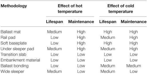
Table 1. Effect of temperature to bridge approach material and maintenance.
Impacts of Flash Floods and Rainfall
Temperature, rain, and flooding can affect railway systems and infrastructure. Rain can change daily temperatures, affecting the expansion and contraction of materials. Water from rainfall can affect infrastructure lifespans via faster deterioration of components such as elastic pads, concrete, and ballast. Moreover, flash floods can have enormous effects on railway lines before, during, and after drainage from the railway track. They can wash away the ballast that supports the track structure, increase the settlement rate of the subgrade under the ballast, undermine subgrade soil properties, and cause track collapse as in Norway (Heyerdahl et al., 2013). Track components, especially those made from metal, can become rusted and loose. In addition, the corrosion rate of concrete can increase. Rising water from flash floods can affect subgrade compaction characteristics and cause track mud pumping. Since water is an incompressible fluid, it further damages the track formation layers and supporting structures. In addition, operating a train on wet/submerged tracks causes ballast dilation.
The Trent River in the UK has a long history of surface water flooding (Environment Agency, 2010). Trent River data are typically combined with historical rainfall data for benchmarking and calculation of flooding return periods [The National River Flow Archive (NRFA), 20161]. The return period can be calculated using flow rate data from 1997 to 2016. Infrastructure designs usually adopt return periods of 10- to 50-year intervals, depending on the type and importance of the structure. Historical data show that the Trent River in the UK can handle flow rates of approximately 600–800 m3/s. For this study, a flood occurs when the flow rate exceeds 800 m3/s.
Engineering Assumptions and Calculations
To align the lifecycle analyses in this study to the same baseline, this section provides the detailed engineering assumptions used in benchmarking. The same assumptions have been consistently and unbiasedly used in estimates and analyses throughout this study. After adopting identical climate-related probabilities for benchmarking purposes, this study focused on three case studies, including a control case and two sensitivity test cases with extreme temperatures and flooding conditions. In addition, two different bridge spans have been compared to analyze their installation and maintenance costs. This study calculates total costs based on the accounting concepts of incremental cost items and cash flow. Cost breakdowns are briefly appended to the assumptions presented in each section.
Control Case
The costs and maintenance lifecycles of eight different solutions and techniques are presented for this control case. Two different bridge spans were compared. One span was long, whereas the other was short. Assumptions and estimates are shown below.
1. The cross-section of the bridge is illustrated in Figure 3. The railway tracks in this model are standard gage with a length of 28 m. The bridge contains 100 m of double tracks, and the span lengths were derived from median bridge span lengths found in the literature (Fryba, 1996).
2. Material quantities were estimated as follows:
• Ballast mat: the ballast mat size was estimated from the mat area under the ballast on both sides of the track and was determined using the following calculation:
• Rail pad: the rail pad was placed under both tracks and both rails along the bridge track to reduce track stiffness. The rail pad size was estimated as follows:
• USP: based on the assumption that the spacing between sleepers on the track was 0.60 m (Eickhoff et al., 2015), the number of USPs was estimated from the number of sleepers. This calculation includes USPs on bridges and 10 sleepers on each side of the bridge transition. The quantity of USPs required was calculated as follows:
For short-span bridges: sleeper on bridge +20 sleepers at end of bridge
For long-span bridges: sleeper on bridge +20 sleepers at the bridge transition area
Alternatively, the USP requirements can be calculated using the cost/meter of bridge and transition zone. In this case, the quantity of USPs is approximately: 2 × 40 m for a short-span bridge and 2 × 130 m for a long-span bridge.
• Soft baseplate: the baseplate requirements were estimated from the quantity of rail seats on both sides of the track. For this study, the quantity of double-track soft baseplates on the bridge was calculated as follows:
where 0.6 m represents the concrete sleeper spacing.
• Transition slab: existing transition slab data indicates a total cost of approximately €100,000 to perform installation without stopping service (Fara, 2014). This cost includes materials, staff, and possession planning. In addition, the length of the transition slab from the bridge abutment to the embankment zone is approximately 5.5 m. Transition slab sizes are identical for both short- and long-span bridges.
• Embankment method: estimates of the special embankments and compacted zones in the transition area were adopted from the French railway model (Fara, 2014). The bridge was assumed to be 5 m tall, and the quantity of embankment materials was calculated from the area and width of the bridge with 1 m of additional offset material. In addition, the transition slab size remained the same for both short- and long-span bridges.
• Ballast bonding/ballast glue: in this approach, the transition zone was assumed to be identical for both short- and long-span bridges (Kaewunruen, 2014a,b,c). Therefore, the costs were the same for both span lengths.
• Wide sleeper: wider sleepers can typically be installed on both sides of the transition zone. Approximately 5–10 wide sleepers were used on each side (Michas, 2012). The increased dimensions increased the overall sleeper stiffness. As with the transition slab and ballast glue methods, the quantity of wide sleepers remained the same regardless of bridge span length. Notably, this study assumed that the size of the bridge was 10.70 m. However, the use of wide sleepers can expand the overall bridge cross-section (wider track center). Total costs and quantities are shown in Table 2 based on these estimates and various resource life span assumptions.
3. This study considered span lengths were derived from median bridge reinstallation, which affects time and labor costs (according to resource data) for maintenance and renewal, as shown in the following bullet points and Table 3:
• Although the bridge transition and a transition mitigation technique were installed, they may only reduce the rate of maintenance activities such as tamping or track resurfacing.
• It was assumed that there would be no direct maintenance of the ballast mat, USP, wide sleeper, transition slab, embankment zone, or ballast bonding (renewal only).
• Renewal of the UBM was assumed to cost 200 €/m2 (Deutsche Bahn and Hans-Joerg, 2011).
• As shown in Table 2, rail pads should be renewed within 1.7–7 years, but the cost of reinstallation is 90 €/m (Deutsche Bahn and Hans-Joerg, 2011).
• USP renewal costs 250 €/m (Deutsche Bahn and Hans-Joerg, 2011).
• Ballast bonding maintenance cannot take place because it can break during tamping. The glue should be saved for reapplication after tamping, but the cost of ballast bonding remains at 15,000 €/zone (Kaewunruen, 2014a,b,c).
• The approximate track lifespan is 50 years.
• The embankment treatment method can be maintained via stone blowing, compacting, re-ballasting, and embankment material renewal. The cost of renewal embankment material was doubled in this study due to construction/maintenance complications.
4. All of these solutions were assumed to reduce the track impact load at the same rate. This study did not consider damage to rolling stock.
5. Lifecycle analysis was performed using 50-year periods.
6. This study considered the overall incremental cost of materials and construction, as well as the costs of the construction process, materials, labor, etc.
7. This study used a discount rate of 6%. This median rate for governmental projects was adopted from Kaewunruen (2014a,b,c).
8. The base financial year was 2016. Previous year costs were estimated and adjusted to this year.
9. Railway superstructure components, i.e., sleepers, rails, fasteners, etc., must be regularly inspected for maintenance planning. The maintenance frequency is directly related to the substructure and its elements such as ballasts, embankments, USPs, and UBMs. A rail track with a high-quality, well-engineered, well-executed substructure typically has a higher initial cost but lower maintenance costs. In this study, the inspection and maintenance routine was estimated using other conjunction research (Osman et al., 2016a,b).
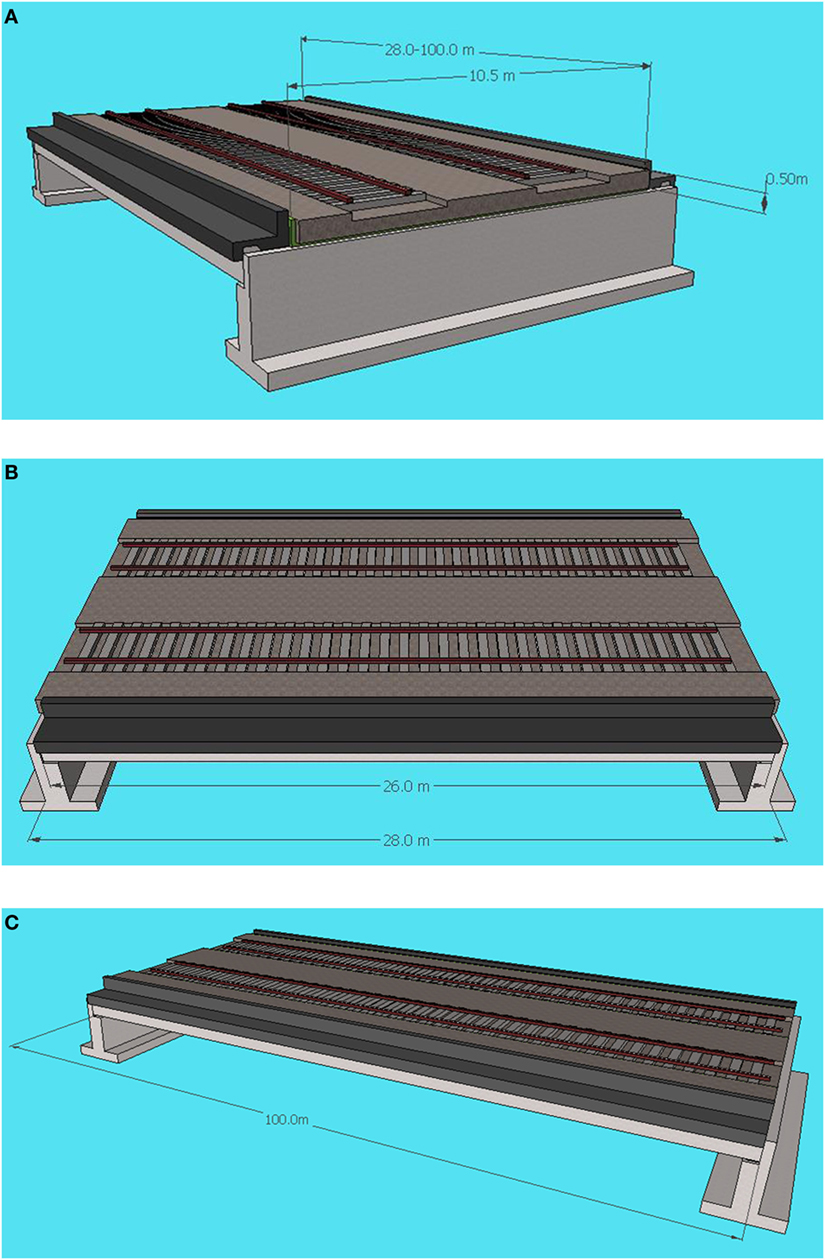
Figure 3. Longitudinal sections of railway bridge. (A) bridge cross section; (B) longitudinal section of short span bridge; (C) longitudinal section of long span bridge.
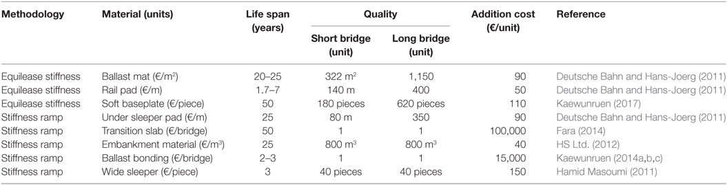
Table 2. Assumptions of additional cost of materials.
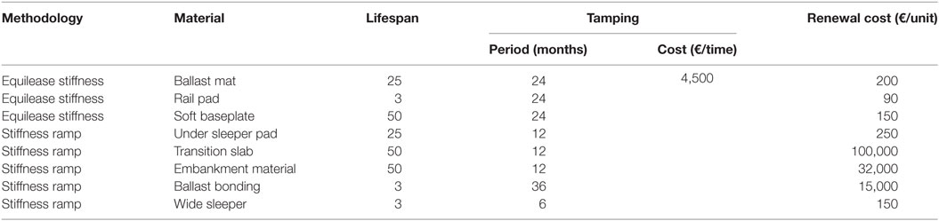
Table 3. Assumptions table for lifespan and maintenance in control case.
Extreme Temperature Cases
Extreme temperatures include both extremely hot and cold weather, ranging from −10 to +40°C. Assumptions related to extreme temperatures are applied to both long- and short-span bridges. Infrastructure lifecycle and maintenance assumptions are influenced by extreme temperatures and are shown below:
1. The ballast mat lifetime is affected by extreme temperatures. The mats are made from PUR, which can withstand temperatures of −20 to 70°C (Trelleborg Engineered Products Australia Pty Ltd., 20162). However, the ballast mat glue or seam can lose its resistance to high temperatures. Extremely high or low temperatures can decrease ballast mat lifetimes by 20 years. Although extreme temperatures may not damage ballast mats, they can reduce ballast mat elasticity or render the elasticity dysfunctional (Huntsman International LLC, 2016). This causes maintenance rates to increase.
2. Low temperatures decrease rail pad lifespans because the plastic material gradually tears off along the vertical axle. The rail pad lifespan used to analyze the low-temperature case was 2 years. The maintenance frequency increased every 12 months due to the effect of temperature on the elastic pad. Extreme temperatures affect rail pads and ballast pads in similar ways. The elasticity of the rail pad is affected by extremely cold conditions that increase the track stiffness. Rail pads can become over-elastic in the summer, which causes track stiffness differentials (Wei et al., 2016).
3. Extreme temperatures affect soft baseplates, which consist of a plastic material (similar to USPs), polymers, and a fastening system (Kockott, 1989). The soft baseplate lifetime is reduced to 25 years, and more frequent maintenance is required.
4. USPs are affected in the same way as rail pads and soft baseplates due to their similar material behaviors. The USP lifespan decreases to 20 years with maintenance every 6 months, according to an EVA polymer study (Agroui et al., 2015).
5. The transition slab and embankment are not affected by the temperature because the former contains a concrete slab underneath its surface. Embankment soil including clay, and sand is not affected by temperature changes in the range of 5–40°C (Yavari, 2016).
6. Ballast bonding from the use of MC 70 ballast bonding material can withstand temperatures between 6 and 40°C (MC-Bauchemie Müller GmbH & Co. KG, 2016), but can be affected by temperature. Low temperatures cause the bonding ballast to crack more easily than in the control condition. Hence, the ballast bonding lifespan is reduced by 2 years and tamping must always be done alongside bonding.
7. Wide sleepers are typically easy to crack because they have longer moment arms than ordinary sleepers. However, temperatures between 0 and 40°C do not affect concrete (Arioz, 2007).
The lifespan and maintenance period of the bridge transition zone are presented in Table 4 based on the assumptions above.
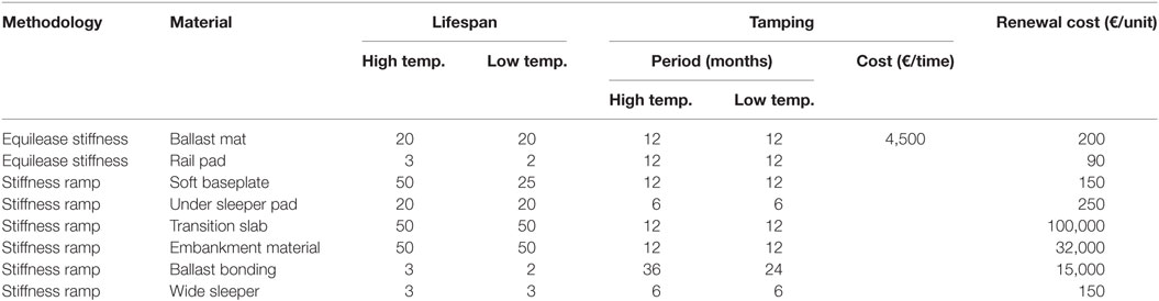
Table 4. Lifespan and maintenance in case of extreme temperature.
Flash Flooding Case
In general, flash flooding and temperature have different effects. The former does not induce rail expansion or contraction that can produce additional internal forces within the steel rail. The railway track is affected by external forces due to fluid flow and moving objects. On the bridge, rain can drain via pipes or gaps between track sleepers/transoms over truss bridges. Naturally, the bridge transition area is the interface by which track surface runoff (or drainage water) flows to the river. High-velocity water flow to the bridge transition area can damage sleepers, embankments, substructures, and other track and bridge components. The assumptions associated with this case included:
1. This analysis considered flood damage to ballast and track materials based on assumptions related to the effect of flooding on track component lifespans and the frequency of re-ballasting. Detailed assumptions regarding relevant maintenance methodologies are summarized in Table 5. This analysis used a flood return period of 10 years, which is considered typical for the UK.
2. Ballast mats are waterproof and are not affected by flash floods (Trelleborg Engineered Products Australia Pty Ltd., 2016). However, flash flooding can increase the rate of ballast loss as the friction between the ballast mat and gravel is less than that between the ballast and subgrade. Thus, it is assumed that re-ballasting is more frequent than with other methods.
3. USPs are not usually affected by flash floods, especially if they are short (Gardner, 1981). However, they can be affected by ballast movement (rotation and translation) caused by floods. The USPs are installed between the ballast and sleeper and can be affected by granular collision or abrasion. The natural characteristics of elastomer materials affect USP lifecycles. The bonding glue interfaces between sleeper pads and sleepers can be damaged by a flash flood.
4. Embankment treatment techniques can be affected directly because flash floods increase the subgrade settlement rate and wash away both ballast and embankment materials (Australian Transport Safety Bureau, 2011). Total ballast loss and significant embankment erosion can often be observed annually, especially in North Queensland.
5. Transition slabs can be affected by surges in subgrade settlement rates above and below the concrete slab. These surges can reduce lifespan of the slab (European Environment Agency, Gropo Fomento, Ministerio de Agricultura, Alimentacion y Medio Ambiente, 2013; Fara, 2014).
6. Ballast bonding is not affected significantly since the bonded ballast can remain flooded and the glue increases interlocking between granular ballast elements, thus enhancing the bonds between ballast packs along the transition zone. Moreover, water drains freely through voids between sections of glued ballast gravel (Lakušic et al., 2010).
7. The lifespans of other methods were assumed to remain the same as in the control case. The only additional cost assumed was re-ballasting due to ballast loss.
8. Re-ballasting was considered in the flash flood case and was calculated based on a re-ballasting effort on the bridge transition area (20 m from the bridge section, at €650/m).
9. The analysis framework is shown in Table 4.
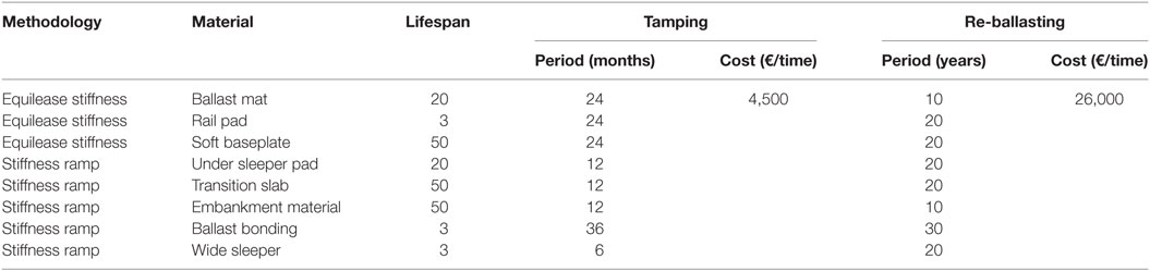
Table 5. Assumptions table for lifespan and maintenance in case of flash flood.
Life Cycle Costs
Life cycle cost assessments for the four cases are presented and discussed separately. Notably, the most suitable outcome is heavily influenced by climate variability and railway bridge length. In this study, single extreme events were considered. The effects of multiple hazards on life cycle costs are outside the scope of this paper, but will be studied in the future.
Control Case
The total costs of each method are shown in Figures 4 and 5. Soft baseplates are the most economical solution for short-span bridges with a 50-year lifespan, while wide sleepers represent the most expensive method due to the low lifespan and high annual maintenance cost of the technique. These costs are driven by various expenses associated with larger track centers. For a long-span bridge, the costs of using a rail pad, USP, UBM, or soft baseplate are more than double those calculated with a short-span bridge. The most expensive long-span bridge method is the use of only rail pads, while the most economical methods are ballast bonding and embankment treatment. Interestingly, the total costs of transition slabs, embankments, ballast bonding, and wide sleepers are the same for long and short spans, as the transition zone does not change with the bridge length.
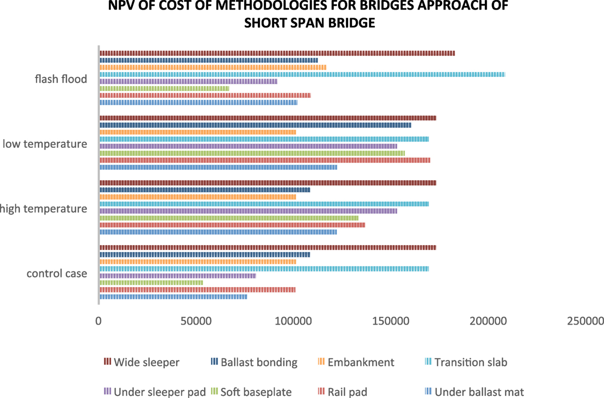
Figure 4. Net present value (NPV) of total cost of bridge approach treatment methodologies for short-span bridge in four cases.
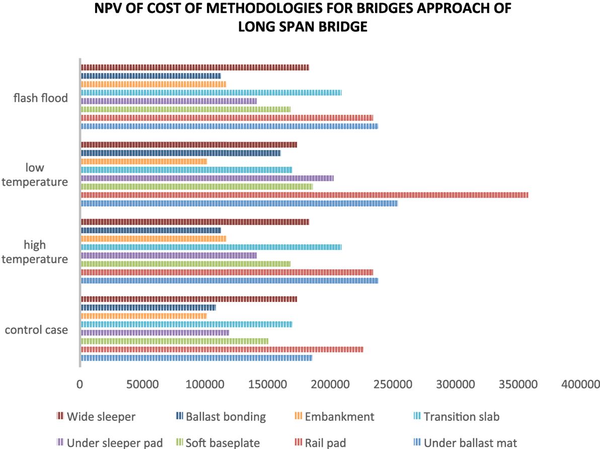
Figure 5. Net present value (NPV) of total cost of bridge approach treatment methodologies for long-span bridge in four cases.
In addition, the total costs of each methodology can be reduced. For example, much of the cost of a transition slab is that of installation on an existing bridge, which would otherwise increase the complexity and construction management costs. In the case of brown field projects, physical constraints such as track spacing and clearance increase project difficulty, resulting in increased cost and delay. On the other hand, the transition slab construction cost can be reduced for new railway bridges (green field projects) via proper design and planning. Embankment treatments and UBMs are quite appropriate for greenfield areas, but are much more expensive in brownfield areas. In addition, the costs of USPs and rail pads depend on the sleeper spacing and bridge length.
Extreme Temperature
Extremely high and low temperatures cause different effects. Most elastic materials function correctly at high temperatures that do not exceed 40°C, but are affected significantly by temperatures below 5°C. Thus, the two types of extreme temperatures are discussed separately.
Extremely High Temperature
Figures 4 and 5 summarize the net present values of the mitigation methods when exposed to extreme temperatures. At high temperatures, ballast bonding and embankment treatments are the most economical for both long- and short-span bridges with a 2% difference as shown in Figures 4 and 5. On the other hand, wide sleepers and transition slabs are the most expensive methods for short-span bridges, with a 5% difference. The life cycle costs of UBMs, USPs, and rail pads suggest that they are the most expensive methods for long-span bridges. The costs of techniques that use elastomer materials, including ballast mats, rail pads, and USPs, can rise in extreme temperatures due to the nature of the materials. Although the embankment method is the most economical, it may not be sufficient alone in brown field reconstruction or if the stiffness difference is high (Fara, 2014).
Extremely Low Temperatures
The costs of combined mitigation methods can be recalculated using an accounting finance approach. An initial study found that combined approaches can be quite costly (Setsobhonkul, 2016). Thus, only individual methods are compared and presented in this paper. According to Figures 4 and 5, embankment treatments and UBMs represent the best methods for both short- and long-span bridges at extremely low temperatures, with a 15% cost differential noted. Wide sleepers provide the worst financial performance. Rail pads and UBMs are the most expensive methods for long-span bridges, while embankment treatment is the most economical option. However, embankment treatments sometimes must be used in conjunction with other methods, depending on the difference in track stiffness. Adverse effects may occur when the track stiffness difference is too high. Strategy and material selection for bridge transitions should thus consider factors introduced by extreme temperature effects.
Flash Floods
In the flooding case illustrated in Figures 4 and 5, the soft baseplate technique is the most economical method for short-span bridges, and costs approximately €67,000 for 50 years. The ballast bonding is the most suitable method for long-span counterparts. The UBM, USP, and rail pad options incur similar costs with a difference of approximately 10%. For long-span bridges, the costs of UBMs, rail pads, and soft baseplates are more than double those of transition slabs, embankment treatment, and ballast bonding. Ballast bonding is the most economical option for long-span bridges and offers acceptable costs for short-span bridges. By contrast, UBMs and rail pads are among the most expensive methods for this extreme case.
Indeed, flash floods can affect every mitigation method used in the transition zones of bridge approaches. Flash floods cause the total costs of all techniques to increase significantly. Considering the increase in cost relative to the control case, the ballast bonding technique is best because the bonded ballast deters material loss. UBMs represent the worst method because they can increase the rate of ballast loss due to reduced ballast–subgrade friction. Notably, floodwater does not directly affect materials other than the soil and subgrade since the UBM acts as an isolation layer. However, the embankment can be affected much more than the ballast. The embankment can be washed away, resulting in railway infrastructure failure in heavy flash flooding and cases with flood-borne debris. Moreover, the seepage force from floodwater can increase the embankment settlement rate and reduce the strength of the sub ballast. Nevertheless, the effect of flash flooding can be reduced by using a flood barrier or other flood protection to shield the railway track and transition zone. This last strategy is not within the scope of this paper, but will be investigated in the future.
Carbon Emissions
Issue of Carbon Emissions
Environmental impacts are important to railways and passengers due to concerns about environmental threats. Individual consumption of goods usually leaves a carbon footprint, and regulations often require companies to report carbon emissions (The Secretary of State, 2013). In some countries such as Norway, companies are taxed for carbon emissions (Annegrete Bruvoll, 2004). In the UK, passenger and freight transport account for 14.5 and 8.8% of carbon emissions, respectively. Cars and taxis contribute the most heavily at 12.7% followed by passenger rail and the London underground at 0.5 and 0.07%, respectively (Association of Train Operating Companies, National Rail, 2007).
Carbon Emission Calculation and Life Cycle Analysis
In a railway system with various subsystems and components, three main factors should be considered: emission factors (EFs), distance, and product weight (Hoen et al., 2010). The EF is constant regardless of the methodology, engine, activity, or material used. The distance of travel and the weight vary based on the fuel type, engine efficiency, quantity, size, and material used.
The analysis of carbon emissions during the bridge transition lifecycle considers installation and renewal materials, as well as maintenance processes. Maintenance process emissions depend on the frequency of maintenance, as mentioned in the Section “Engineering Assumptions and Calculations.” Figure 6 shows a comparison of carbon emissions from rail resurfacing machinery for each maintenance device in working and traveling modes. It includes emissions from the ballast regulator (BX 055 and BX 060), ballast stabilizer (DS003), line tamper, and switch tamper (TJ 061). Although the emission rates are the same, the total carbon emissions from these machines depend on the type of emission gas/fuel used.
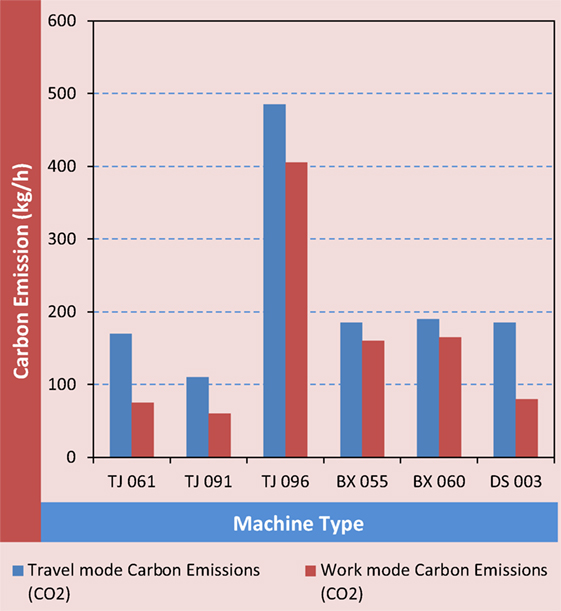
Figure 6. Comparison of carbon emissions from rail resurfacing machineries (Krezo et al., 2014).
A field investigation and parametric study of greenhouse gas emissions from railway plain-line renewals (Krezo et al., 2016) shows that CO2-e emissions are related to construction material consumption. The embedded CO2-e emission per unit of track can be evaluated as follows:
where k is the material index, N is the total number of material types used in track construction, EFk is the embedded emissions factor for a material of type k (kg/kg), and QMk is the quantity of material k required per meter of track construction (kg/m).
Carbon emissions from the materials and the treatment of each methodology are shown in Table 6. The carbon emission calculations are based on lifespan and quantity in the control case, as mentioned in the Section “Engineering Assumptions and Calculations.” Material lifespans affect carbon emissions, as seen in the cases of soft baseplates, embankment treatments, and transition slabs. Rail pads and USPs produce the lowest carbon emission rates before maintenance emissions are considered. Ballast bonding and wide sleepers have the highest emission rates due to low material lifespans. This indicates that more frequent work (construction, tamping, etc.) is required over the system lifetime.
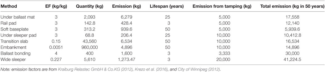
Table 6. Carbon emission from bridge approach material in control case.
In transition zones that require frequent maintenance, carbon emissions from maintenance processes are significant. Table 6 shows calculated total carbon emissions from the control case in each 50-year period. The material and tamping machine carbon emissions are calculated by assuming that the machine emits carbon during 1 h of work and 1 h of travel. The wide sleeper method exhibits the highest EF and lowest lifespan and thus produces the largest amount of CO2-e. The soft baseplate technique requires the fewest emissions due its long material lifespan and low maintenance requirements. Interestingly, the total emission rate from the tamping machine exceeds that from the material with most methods other than ballast bonding and UBMs.
Figure 7 presents the total carbon emissions of each method in four different scenarios: the control case, extremely high temperatures (around 40°C), relatively low temperatures (below 0°C), and flash flooding. The UBM method emits the most carbon across a 50-year period in all cases, with emissions approximately eight times higher than with soft baseplates. Soft baseplates are the best material with regard to carbon emissions. The technique emits approximately 10,000 kg of carbon over 50 years under extreme temperature conditions, and less than 10,000 kg in control case or with flash flooding. Interestingly, the carbon emissions from transition slabs and embankment treatments change little, as the effects on maintenance are insignificant.
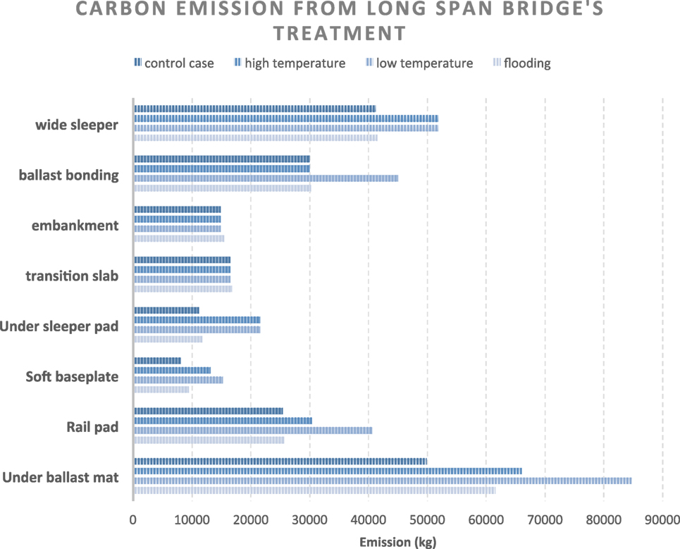
Figure 7. Carbon emission from long-span bridge approach treatment and maintenance in different cases.
Figure 8 shows that wide sleepers always produce the highest carbon emission methods when used with short-span bridges, while soft baseplates offer the best carbon performance. In the control and flash flood cases, the emission rates from the under sleeper and rail pad methods are lower than those of the transition slab and embankment treatment methods, with a difference of approximately 10%. In addition, carbon emissions from ballast bonding, transition slabs, and wide sleepers are similar for both long- and short-span bridges. Further CO2 emission analyses can be found in Setsobhonkul (2016).
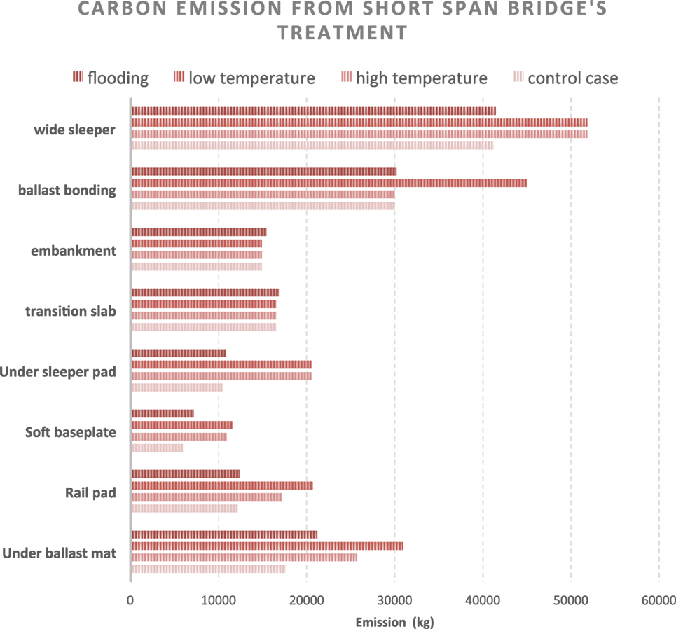
Figure 8. Carbon emission from short-span bridge ends treatment and maintenance in different cases.
Conclusion
Various methods can be used to reduce the impact loads caused by differences in track stiffness at bridge approaches. There are two main solution strategies: reduction of track stiffness on railway bridges and provision of gradual increases in track stiffness from the embankment area to the bridge using stiffness transition zones. This unprecedented research considers the maintenance and installation life cycle costs of eight commonly adopted methods, including UBMs, rail pads, and soft baseplates, which are used to equalize track stiffnesses on bridges, as well as USPs, transition slabs, embankment treatments, ballast bonding, and wide sleepers, which are used to increase track stiffnesses gradually.
Novel Findings
The lifecycle assessments of bridge transition zones indicate that each method requires a variety of individual components and installation methods with varying installation and maintenance costs. The total cost of each technique depends on environmental parameters and railway bridge span lengths. The construction site condition is important as well. Some strategies such as the embankment method, transition slabs, and UBMs are suitable only for greenfield construction.
Control Case
Soft baseplates and elastic rail pads are the best options for the control case. Both options have optimized costs, and the price difference between them is less than 25% for a short-span bridge. The ballast bonding and embankment treatment techniques are the most economical methods for long-span bridges with 50-year lifecycles.
Extremely High Temperatures
High temperatures can affect elastic pad properties. The elastic pad may lose its elasticity due to the nature of the elastomer materials. In this case, ballast bonding and embankment treatment techniques offer the best performance for both short- and long-span bridges, with a cost difference of less than 7%.
Extremely Low Temperatures
Extremely low temperatures affect elastomers even more than high temperatures. In these conditions, embankment treatment is the best method for both short- and long-railway bridge spans. The UBM option is also acceptable in extremely low-temperature conditions, and costs approximately 20% more than embankment treatment for short-span bridges. For long-span bridges, the second best option is ballast bonding, with a difference of around 25% from the embankment treatment method.
Flash Flooding
In a flash flooding situation, the most suitable method is the use of soft baseplates, followed by USPs for short-span bridges and ballast bonding for long-span bridges. The lifecycle costs of USPs are approximately 30% higher than those of soft baseplates.
Carbon Emissions
The soft baseplate method is the best approach for minimization of carbon emissions with both short- and long-span bridges across all four cases. By contrast, wide sleepering and UBMs provide the highest carbon emissions with short- and long-span bridges, respectively, in all four cases. A summary of the carbon emissions and costs of the bridge transition methods is illustrated in Figure 9.
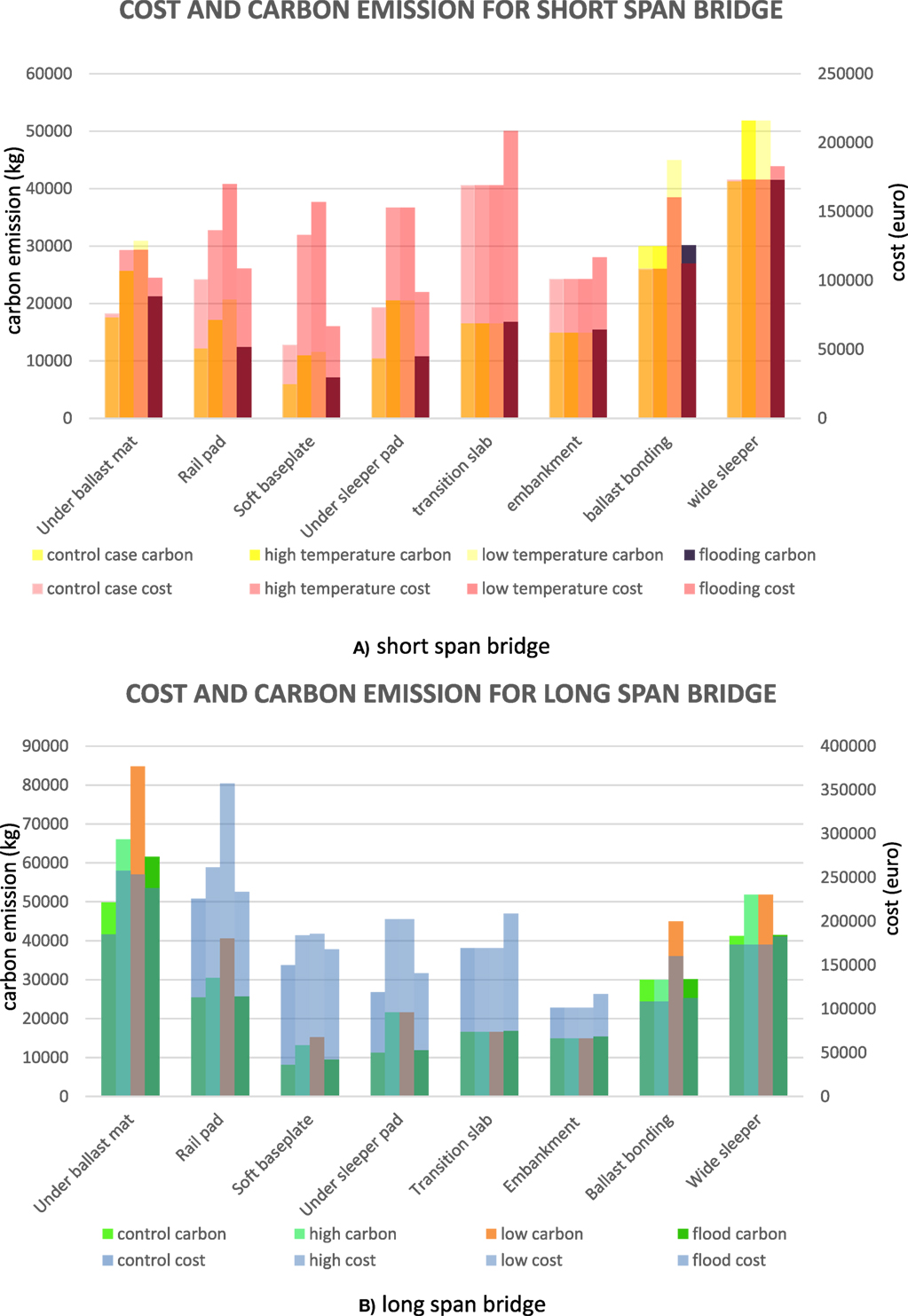
Figure 9. Cost and carbon emission. (A) Short-span bridge. (B) Long-span bridge.
Recommendations
Lifecycle economic and environmental costs have improved insights regarding track design, construction, and maintenance that can significantly enhance infrastructure resilience. Overall, elastic rail pads, soft baseplates, and UBMs are suitable for short-span bridges. By contrast, transition slabs, ballast bonding, and embankment treatment should be considered for long-span bridges.
However, long-span transition mitigation method selection is best done by considering lifecycle cost and carbon emissions for the design, maintenance, and renewal of a particular bridge. It is also important for railway engineers to consider whether the activity is for a brownfield or greenfield site. This research evaluates the life cycle performances of railway bridge approaches using four separate sensitivity parameters. In the future, we will consider combined effects (multiple hazards) and the stochastic probabilities of extreme events both individually and collectively.
Author Contributions
SS, SK, and JS developed the original concept and scope; analyzed and discussed the results. SS and SK performed life cycle evaluation and wrote the manuscript. SK and JS discussed and edited the manuscript.
Conflict of Interest Statement
The authors declare that the research was conducted in the absence of any commercial or financial relationships that could be construed as a potential conflict of interest.
The reviewer, GF, and handling editor declared their shared affiliation, and the handling editor states that the process nevertheless met the standards of a fair and objective review.
Funding
The authors gratefully acknowledge the British Department for Transport for the T-TRIG Grant for Transport-Technology Research Innovations Grant Scheme, Project No. RCS15/0233. Special thanks are also given to the European Commission for financial sponsorship via the H2020-MSCA-RISE Project No. 691135 RISEN: “Rail Infrastructure Systems Engineering Network”, which enables a global research network to tackle the grand challenge of railway infrastructure resilience in the face of physical natural and unnatural threats, as well as advanced sensing under extreme conditions (www.risen2rail.eu).
Footnotes
References
Agroui, K., Collins, G., Oreski, G., and Ouadjaout, L. D. (2015). Effect of crosslinking on EVA-based encapsulant properties during photovoltaic module fabrication process. Revue des Energ. Renouvelables 18, 303–314.
Annegrete Bruvoll, B. M. (2004). Greenhouse gas emission in Norway: do carbon taxes work? Energy Policy 32, 493–505. doi: 10.1016/S0301-4215(03)00151-4
Arioz, O. (2007). Effects of elevated temperatures on properties of concrete. Fire Saf. J. 42, 516–522. doi:10.1016/j.firesaf.2007.01.003
Association of Train Operating Companies, National Rail. (2007). Baseline Energy Statement – Energy Consumption and Carbon Dioxide Emissions on the Railway. London, UK: ATOC.
Auersch, L. (2006). Dynamic axle loads on tracks with and without ballast mats. Proc. Inst. Mech. Eng. 220, 169–183. doi:10.1243/09544097F00105
Australian Transport Safety Bureau. (2011). Derailment of Freight Train 7AD1at Edith River. Australian Capital Territory: Australian Transport Safety Bureau.
Azzoug, A., and Kaewunruen, S. (2017). RideComfort: a development of crowdsourcing smartphones in measuring train ride quality. Front. Built Environ. 3:3. doi:10.3389/fbuil.2017.00003
Binti Sa’adin, S. L., Kaewunruen, S., and Jaroszweski, D. (2016a). Risks of Climate Change with Respect to the Singapore-Malaysia High Speed Rail System. Climate 4, 65.
Binti Sa’adin, S. L., Kaewunruen, S., and Jaroszweski, D. (2016b). Operational readiness for climate change of Malaysia high-speed rail. Proc. Inst. Civil Eng. Transp. 169(5), 308–320.
Binti Sa’adin, S. L., Kaewunruen, S., and Jaroszweski, D. (2016c). Climate change vulnerability and adaptation for the Singapore-Malaysia high-speed rail system. Ingenieur 66(2), 44–54.
Binti Sa’adin, S. L., Kaewunruen, S., and Jaroszweski, D. (2017). Heavy rainfall and flood vulnerability of Singapore-Malaysia high speed rail system. Aust. J. Civil Eng. doi:10.1080/14488353.2017.1336895
City of Winnipeg. (2012). Appendix 7, Winnipeg Sewage Treatment Program. Canada: City of Winnipeg. Available at: http://www.winnipeg.ca/finance/findata/matmgt/documents/2012/682-2012/682-2012_Appendix_H-WSTP_South_End_Plant_Process_Selection_Report/Appendix%207.pdf
Deutsche Bahn, A. G., and Hans-Joerg, T. (2011). State of the Art Review of Mitigation Measures on Track Deliverable D3.1. Paris: International Union of Railways.
Eickhoff, B., Mazzola, L., Bezin, Y., Tucker, G., Stradtmann, H., Haigermoser, A., et al. (2015). Track loading limits and cross acceptance of vehicle approvals. Proc. Inst. Mech. Eng. F 229, 710–728. doi:10.1177/0954409715575092
Environment Agency. (2010). River Trent Catchment Flood Management Plan. Solihull: Environment Agency Sapphire East.
European Environment Agency, Gropo Fomento, Ministerio de Agricultura, Alimentacion y Medio Ambiente. (2013). Climate Change Adaption Needs of the Core Network of Transport Infrastructure in Spain.
Fara, A. (2014). Transition Zones for Railway Bridges: A Study of the Sikån Bridge. Lulea: Luleå University of Technology Department of Civil, Environmental and Natural Resources Engineering.
Gardner, R. J. (1981). Effect of long term humid aging on plastics. Polymer Eng. Sci. 21, 557–565. doi:10.1002/pen.760210908
Hamid Masoumi, P. V. (2011). “Attenuation of ground-borne vibration affecting residents near railway lines,” in Seventh Framework Program, Brussels.
Hanasaka, M. (2016). Influence of Temperature on Vibration Reduction Performances of Elastic Track Material. Tokyo: Railway Technic Research Institute.
Heyerdahl, H., Høydal, Ø, Nadim, F., and Kalsnes, B. G. (2013). “Rainfall-induced collapse of old railway embankments in Norway,” in International Conference on Soil Mechanics and Geotechnical Engineering (Paris: Norwegian National Rail Administration).
Hoen, K. M. R., TanJ, T., Fransoo, C., and van Houtum, G. J. (2010). Effect of Carbon Emission Regulations on Transport Mode Selection in Supply Chains. Eindhoven, the Netherlands: School of Industrial Engineering, Eindhoven University of Technology.
Huntsman International LLC. (2016). A Guide to Thermoplastic Polyurethanes (TPU). Available at: http://www.huntsman.com/portal/page/portal/polyurethanes/Media%20Library/global/files/guide_tpu.pdf
Jenks, C. W. (2006). Design of Track Transitions. (Washington DC, USA: Transportation Research Board).
José, N., and Varandas, P. H. (2011). Dynamic behaviour of railway tracks on transitions zones. Comput. Struct. 89, 1468–1479.
Kaewunruen, S. (2013). “Acoustic and dynamic characteristics of a complex urban turnout using fibre-reinforced foamed urethane (FFU) bearers,” in Proceedings of 2013 International Workshop on Railway Noise (Uddevalla, Sweden).
Kaewunruen, S. (2014a). Impact damage mechanism and mitigation by ballast bonding at railway bridge ends. Int. J. Railw. Technol. 3, 1–22. doi:10.4203/ijrt.3.4.1
Kaewunruen, S. (2014b). Monitoring structural deterioration of railway turnout systems via dynamic wheel/rail interaction. Case Stud. Nondestr. Test. Eval. 1, 19–24. doi:10.1016/j.csndt.2014.03.004
Kaewunruen, S. (2014c). Monitoring in-service performance of fibre-reinforced foamed urethane sleepers/bearers in railway urban turnout systems. Struct. Monit. Maint. 1, 131–157. doi:10.12989/smm.2014.1.1.131
Kaewunruen, S. (2016). “Field performance to mitigate impact vibration at railway bridge ends using soft baseplates,” in World Congress on Railway Research (Milan: WCRR), 1–10.
Kaewunruen, S. (2017). Monitoring of rail corrugation growth on sharp curves for track maintenance prioritization. Int. J. Acoust. Vib. (in press).
Kaewunruen, S., Lewandrowski, T., and Chamniprasart, K. (2017). Dynamic responses of interspersed railway tracks to moving train loads. Int. J. Struct. Stab. Dyn. doi:10.1142/S0219455418500116
Kaewunruen, S., Sussman, J. M., and Einstein, H. H. (2015). Strategic framework to achieve carbon-efficient construction and maintenance of railway infrastructure systems. Front. Environ. Sci. 3:6. doi:10.3389/fenvs.2015.00006
Kaewunruen, S., Sussman, J. M., and Matsumoto, A. (2016a). Grand challenges in transportation and transit systems. Front. Built Environ. 2:4. doi:10.3389/fbuil.2016.00004
Kaewunruen, S., Aikawa, A., and Remennikov, A. M. (2016b). “Effectiveness of soft baseplates and fastenings to mitigate track dynamic settlement at transition zone at railway bridge approaches,” in Proceedings of the Third International Conference on Railway Technology: Research, Development and Maintenance, Civil-Comp Press (Stirlingshire: Civil-Comp Press).
Kang, Y. S., Yang, S. C., Lee, H. S., Kim, Y. B., Jang, S. Y., and Kim, E. (2008). A Study of Track and Train Dynamic Behavior of Transition Zone. Available at: http://www.uic.org/cdrom/2008/11_wcrr2008/pdf/I.1.4.1.4.pdf
Kim, H. (2016). Trackside Measurement of Critical Zones in Railway Tracks. Birmingham: The Birmingham Centre for Railway Research and Education.
Kockott, D. (1989). Natural and artificial weathering of polymers. Polym. Degrad. Stab. 25, 181–208. doi:10.1016/S0141-3910(89)81007-9
Kraiburg Relastec GmbH & Co.KG. (2012). KRAIBURG SBM – sub ballast mat. Available at: http://www.kraiburg-relastec.com/damtec/es/assets/9480_04_01062012_kraiburg-sbm_gb.pdf
Krezo, S., Mirza, O., He, Y., Kaewunruen, S., and Sussman, J. M. (2014). “Carbon emissions analysis of rail resurfacing work: a case study and practical guidelines,” in Proceedings of the Second International Conference on Railway Technology: Research Development and Maintenance, ed J. Pombo, Ajaccio, Corsica.
Krezo, S., Mirza, O., He, Y., and Kaewunruen, S. (2016). Field investigation and parametric study of greenhouse gas emissions from railway plain-line renewals. Trans. Res. D 42, 77–90. doi:10.1016/j.trd.2015.10.021
Lakušić, S., Ahac, M., and Haladin, I. (2010). “Track stability using ballast bonding method,” in Proceeding of the 10th Slovenian Road and Transportation Congress, IN PROMETU, Portorož, 20–22. Oktobra 2010, Portorož, Slovenia.
Lei, X., and Zhang, X. L. (2010). Analyses of dynamic behavior of track transition with finite elements. J. Vib. Control 17, 1733–1747.
Lund, H., and Åswärdh, Å (2014). Transition Zones between Ballasted and Ballastless Tracks. Lund: LTH School of Engineering at Campus Helsingborg, Department of Technology and Society, Lund University.
MC-Bauchemie Müller GmbH & Co. KG. (2016). MC-Ballast Bond 70. Available at: http://buildingchemicalsupplies.co.nz/doc/mc/datasheets/BallastBond/MC-Ballastbond70.pdf
Michas, G. (2012). Slab Track Systems for High-Speed Railways. Stockholm, Sweden: School of Architecture and the Built Environment Royal Institute of Technology.
Miguel Sol-Sánchez, F. M.-N.-G. (2015). The use of elastic elements in railway tracks: a state of the art review. Constr. Build. Mater. 293–305. doi:10.1016/j.conbuildmat.2014.11.027
Nyström, P., and Prokopov, A. (2011). Spårkonstruktioner för 320 km/h –Övergångskonstruktioner. Borlänge, Stockholm: Trafikverket.
Osman, M. H. B., Kaewunruen, S., Jack, A., and Sussman, J. M. (2016a). Need and opportunities for a ’Plan B’ in rail track inspection schedules. Proc. Eng. 161, 264–268. doi:10.1016/j.proeng.2016.08.549
Osman, M. H. B., Kaewunruen, S., An, M., and Dindar, S. (2016b). “Disruption: a new component in the track inspection schedule,” in 2016 IEEE International Conference on Intelligent Rail Transportation, ICIRT 2016 (Birmingham, UK: Elsevier), 248–253.
Peeling, P. A. (2012). Railway Noise Mitigation Factsheet 06: Viaducts and Bridges. Available at: http://www.51m.co.uk/wp-content/uploads/2013/08/Factsheet-06-nov-2012-Viaducts-Bridges.pdf
Pita, L. (2002). “The importance of vertical stiffness of the track on high–speed lines,” in Transportation Research Board 81st Annual Meeting (Washington, DC).
Puzavac, L., Popović, Z., and Lazarević, L. (2012). Influence of track stiffness on track behaviour under vertical load. Promet 24, 405–412. doi:10.7307/ptt.v24i5.1176
RSSB. (2005). Rail Safety & Standards Board: Review of the Effects of Track Stiffness on Track Performance. UK: RSSB.
Sañudo, R., Miranda, M., Markine, V., and delĺOlio, L. (2016). The influence of train running direction and track supports position on the behaviour of transition zones. Transp. Res. Proc 18, 281–288. doi:10.1016/j.trpro.2016.12.037
Schilder, R. (2013). “USP (under sleeper pads) – a contribution to save money in track maintenance,” in AusRAIL PLUS (Sydney: AusRAIL PLUS).
Setsobhonkul, S. (2016). Life Cycle Assessment of Railway Bridge Approach Considering Extreme Climate Events, MSc Thesis. Railway Systems Engineering and Integration, University of Birmingham, UK, 155.
Sussmann, T. R. (2001). Fundamental non-linear track load-deflection behavior for condition evaluation. Trans. Res. Rec. 1742, 61–67. doi:10.3141/1742-08
The Secretary of State. (2013). The Companies Act 2006 (Strategic Report and Directors’ Report) Regulations 2013. Available at: http://www.legislation.gov.uk/uksi/2013/1970/contents/made
Transportation Technology Center, Inc. (TTCI). (2006). Design of Track Transitions. Colorado, USA: Transportation Technology Center, Inc. (TTCI).
Trelleborg Engineered Products Australia Pty Ltd. (2016). Ballast-Mats-Waterproofing. Available at: http://trelleborg.com.au/wp-content/uploads/2016/02/9902-Ballast-Mats-Waterproofing.pdf
Tschumi, D. H. (2012). “Basis of design of railway bridges, some important points,” in Bridge Design with Eurocodes (Ispra, Italy: European Commission, Russian Federation, European Committee for Standardization).
Wei, K., Liu, Z.-X., Liang, L.-C., and Wang, P. (2016). An investigation into the effect of temperature-dependent stiffness of rail pads on vehicle-track coupled vibrations. J. Rail Rapid Transit 231, 1–11.
Witt, S. (2008). The Influence of Under Sleeper Pads on Railway Track Dynamics. Linkoping: Department of Management and Engineering, Linköping University.
Wu, L., and Kaewunruen, S. (2017). “Performance and durability of concrete structures in railway environment under extreme climate,” in The First International Conference on Rail Transportation (Chendu, China)
Keywords: bridge transition, ballast mat, under sleeper pad, rail pad, soft baseplate, ballast bonding, transition slab, wide sleeper
Citation: Setsobhonkul S, Kaewunruen S and Sussman JM (2017) Lifecycle Assessments of Railway Bridge Transitions Exposed to Extreme Climate Events. Front. Built Environ. 3:35. doi: 10.3389/fbuil.2017.00035
Received: 30 November 2016; Accepted: 23 May 2017;
Published: 19 June 2017
Edited by:
Panagiotis Ch. Anastasopoulos, University at Buffalo, United StatesReviewed by:
Grigorios Fountas, University at Buffalo, United StatesSamuel Labi, Purdue University, United States
Copyright: © 2017 Setsobhonkul, Kaewunruen and Sussman. This is an open-access article distributed under the terms of the Creative Commons Attribution License (CC BY). The use, distribution or reproduction in other forums is permitted, provided the original author(s) or licensor are credited and that the original publication in this journal is cited, in accordance with accepted academic practice. No use, distribution or reproduction is permitted which does not comply with these terms.
*Correspondence: Sakdirat Kaewunruen, sakdirat@hotmail.com, s.kaewunruen@bham.ac.uk