New Frontiers on Seismic Modeling of Masonry Structures
 Salvatore Caddemi
 Ivo Caliò
 Francesco Cannizzaro
 Bartolomeo Pantò
- 1Department of Civil Engineering and Architecture, University of Catania, Catania, Italy
- 2Department of Engineering, Roma Tre University, Rome, Italy
An accurate evaluation of the non-linear behavior of masonry structural elements in existing buildings still represents a complex issue that rigorously requires non-linear finite element strategies difficult to apply to real large structures. Nevertheless, for the static and seismic assessment of existing structures, involving the contribution of masonry materials, engineers need reliable and efficient numerical tools, whose complexity and computational demand should be suitable for practical purposes. For these reasons, the formulation and the validation of simplified numerical strategies represent a very important issue in masonry computational research. In this paper, an innovative macroelement approach, developed by the authors in the last decade, is presented. The proposed macroelement formulation is based on different, plane and spatial, macroelements for the simulation of both the in-plane and out-of-plane behavior of masonry structures also in presence of masonry elements with curved geometry. The mechanical response of the adopted macroelement is governed by non-linear zero-thickness interfaces, whose calibration follows a straightforward fiber discretization, and the non-linear internal shear deformability is ruled by equivalence with a corresponding geometrically consistent homogenized medium. The approach can be considered as “parsimonious” since the kinematics of the adopted elements is controlled by very few degrees of freedom, if compared to a corresponding discretization performed by using non-linear finite element method strategies. This innovative discrete element strategy has been implemented in two user-oriented software codes 3DMacro (Caliò et al., 2012b) and HiStrA (Historical Structures Analysis) (Caliò et al., 2015), which simplify the modeling of buildings and historical structures by means of several wizard generation tools and input/output facilities. The proposed approach, that represents a powerful tool for the structural assessment of structures in which the masonry plays a key role, is here validated against experimental results involving typical masonry monumental substructural elements and numerical results involving real-scale structures.
Introduction
Although masonry represents one of most ancient construction material, the numerical simulation of the actual behavior of masonry structures is still a very complex issue. The main concern is related to the difficulty to characterize a reliable simulation of the high non-linear degrading cyclic response of masonry material whose great variability of mechanical characteristics makes difficult to define a general constitutive law to be applied for all masonry structures (Lourenço et al., 1998; Asteris et al., 2014). The non-linear dynamic behavior of a masonry structures, subjected to earthquake loadings, is also characterized by a complex interaction between in-plane and out-of plane response of masonry walls and is often further complicated by the presence of structural elements with curved geometry such as arches, domes, and vaults. Masonry material provides its mechanical contribution also in mixed-masonry structures, like confined masonry and infilled masonry buildings; in these latter cases, the numerical simulations require the modeling of the complex non-linear interaction of the different structural members contributing to the global bearing capacity of the structural system (Asteris et al., 2011; Caliò and Pantò, 2014).
In the scientific literature, there are many significant examples of applications of the non-linear finite element method (FEM) to historical masonry buildings and churches (Mele et al., 2003; Betti and Vignoli, 2008, 2011; Araujo et al., 2012; Lourenço et al., 2012; Barbieri et al., 2013; Milani and Valente, 2015), however refined FE approaches (Lofti and Shing, 1994; Anthoine, 1997; Gambarotta and Lagomarsino, 1997; Lourenço and Rots, 1997; Berto et al., 2002; Macorini and Izzuddin, 2011) coupled with sophisticated constitutive laws, require a huge computational cost and advanced abilities in the model implementation and in the interpretations of the results. On the other hand, structural engineers need simple and efficient numerical tools, whose complexity and computational demand should be appropriate for practical engineering purposes. For these reasons, in the last decades, many authors proposed simplified or alternative methodologies to predict the non-linear seismic behavior of unreinforced masonry (URM) structures, particularly oriented to buildings (D’Asdia and Viskovic, 1995; Braga et al., 1998; Brenchich et al., 1998; Magenes and La Fontana, 1998; Kappos et al., 2002; Caliò et al., 2005; Chen et al., 2008; Marques and Lourenço, 2011; Raka et al., 2015). Marques and Lourenço (2011) report a comparison between different simplified approaches currently used in academic research and engineering practice. However, most of the simplified methods, currently used in practical engineering, restricted to in-plane behavior of masonry walls, are unsuitable for those masonry structures dominated by the out-of plane seismic response, as in the case of historical monumental buildings and churches. An alternative approach to the non-linear FEM is represented by the rigid-body spring models, specifically formulated with the aim of approximating the macroscopic behavior of masonry walls with reduced degrees of freedom. Some valuable applications of this approach are relative to historical masonry buildings (Casolo and Peña, 2007; Casolo and Sanjust, 2009). A comprehensive review of the current development on numerical issues on masonry mechanics is reported in Lourenço (2002). In the latter works, it is also highlighted that a complex analysis tool does not necessarily provide better results than a simplified one.
In this paper, an innovative modeling strategy for the simulation of the non-linear behavior of URM structures, under static and seismic loadings, capable of accounting for the in-plane and out-of plane behavior of masonry as well as curved geometry masonry structures, is presented. The approach here proposed is based on the concept of macroelement discretization (Caliò et al., 2012a) and has been conceived with the aim of capturing the non-linear behavior of an entire structure through an assemblage of discrete macroelements characterized by different levels of complexity according to the role played in the global model. The basic element has been initially (Caliò et al., 2005) developed for the simulation of the in-plane response of masonry walls and has already received several numerical and experimental validations (Lourenço, 2002; Marques and Lourenço, 2011; Caliò et al., 2012a; Pantò et al., 2015). The basic in-plane element is currently used by the engineering community for masonry building modeling by means of the 3DMacro computer code implementation (Caliò et al., 2012b), endowed with simplified input and output graphical user interfaces. This plane element can be represented through the aid of a simple and unambiguous mechanical scheme since it can be regarded as an articulated quadrilateral with four rigid edges and four hinged vertices connected by two diagonal non-linear springs. Each of the rigid edges can be connected to other elements by means of a non-linear zero-thickness interface. This novel approach has been also recently successfully applied and validated for mixed reinforced concrete–masonry structures and for confined masonry buildings (Caliò et al., 2008; Caddemi et al., 2013; Caliò and Pantò, 2014; Marques and Lourenço, 2014). In this latter case, the infills are modeled by 2D “geometrically consistent” macroelements, while the reinforced concrete frames are modeled by concentrated-plasticity beam columns. The adopted term “geometrically consistent” is used to emphasize that the geometry of the macroelement is consistent with the actual two-dimensional geometry of the infill. Also, in the presence of openings the geometrical consistence is assured through a mesh of macroelements.
However, the basic plane element has been conceived only for the simulation of the non-linear response of masonry walls in their own plane, since the out-of plane response is ignored. To overcome this significant restriction, common to several macroelement simplified approaches in the literature, the plane macroelement has been modified by introducing a third dimension and the relevant additional degrees of freedom (Pantò et al., 2017a; Pantò, 2007; Caddemi et al., 2014). The kinematics of the enriched 3D-macroelement is governed by seven Lagrangian parameters only and allows an efficient simulation of the in-plane and the out-of plane response of masonry walls.
One of the advantages of the proposed macroelement strategy consists in a reduced computational cost if compared to the traditional non-linear finite element modeling. However, another benefit relies on the adopted mechanical calibration strategy that, being based on straightforward fiber discretization, allows the use of simple uni-axial constitutive laws and leads to a very easy interpretation of the numerical results. Based on the above issues, the macroelement approach can be considered not only a reliable numerical tool for academic researches but also an efficient practice-oriented platform.
Many monumental masonry constructions are characterized by the presence of structural elements with curved geometry, such as arches, vaults, domes whose role cannot be neglected in a reliable numerical analysis. For this reason, a further enrichment of the proposed three-dimensional macroelement towards a more general macro-shell-element, able to discretize curved geometry monumental structures, has been introduced (Calió et al., 2010; Cannizzaro, 2010; Caddemi et al., 2015). The shell macroelement was conceived as the extension of the spatial element. Its nucleus is now constituted by an irregular articulated quadrilateral still characterized by four rigid layer edges whose orientation and size are related to the shape of the element and to the thickness of the modeled masonry portion. This more general macroelement strategy is mainly devoted to the numerical simulation of the seismic behavior of historical masonry structures (HMS), and it has been implemented in the software code HiStrA (Historical Structures Analysis) (Caliò et al., 2015), which simplifies the modeling of historical structures by means of several wizard generation tools, suitable to manage complex curved geometries.
The aim of this paper is to provide a comprehensive review of the proposed discrete macroelement strategy and to show its capabilities through different applications to significant benchmark structures for which experimental and/or numerical results are reported in the literature. The paper, although containing a review of different macroelements already proposed by the authors, highlights the novelties of the proposed approach with respect to the existing simplified methods for masonry and monumental structures. Another target of this work is to illustrate a comprehensive parsimonious modeling strategy from the simplest cases, i.e., the regular plane element, to more complicated structural scenarios, e.g., infilled frame structures (IFS) or historical masonry constructions. This paper, although recalling several results already presented in the literature, clearly highlights the proposed strategy which is based on the use of different discrete macroelements characterized by a different level of complexity according to the role played in the overall structural idealizations. All the elements can interact in the same environment leading to a powerful numerical strategy whose computational demand is extremely low if compared to those related to classical non-linear FEM simulations or to rigid-spring-element approaches. The low computational cost and the easiness in the interpretation of the results make this method particularly suitable for the engineering community as well as for the research on the seismic assessment of cultural heritage buildings.
The Proposed Macroelement Strategy: Summary
The macroelement strategy, proposed by the authors in the last years for the non-linear analysis of masonry structures, has been defined according to an original approach within the framework of a discrete element formulation strategy. Such an approach is based on the subdivision of the structure under consideration in several macro-portions (wall, arch, vaults, and so on); then, after a homogenization of the mechanical properties of the components (mortar and units), each portion is regarded as an equivalent continuum whose mechanical properties can be assumed as isotropic or orthotropic depending on the masonry texture. The next step is the discretization of each macro-portion by means of a mesh of an appropriate original macroelement (2D, 3D, or shell). In Figure 1, it is qualitatively reported the subdivision of a part of a masonry dome by means of several macro-portions that, according to a macroelement strategy, will be represented by the corresponding macroelements.
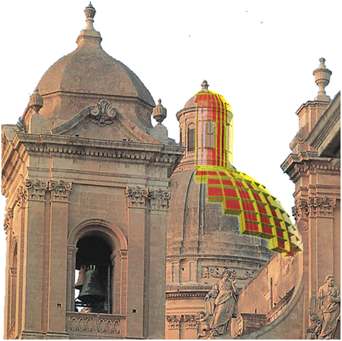
Figure 1. A simplified qualitative representation of the use of shell macroelements for curved geometry monumental structures modeling (Calió et al., 2010).
In this approach each macroelement, that is not rigid, interacts with the adjacent elements through non-linear zero-thickness interfaces and the non-linear behavior of the investigated structure is then captured through an assemblage of macroelements, characterized by different level of complexity according to the role played in the global model.
According to the proposed modeling strategy, the assemblage of the global stiffness and mass matrixes is not based on assigning degrees of freedom to each node and on a subsequent condensation of some of them because of the internal constraints due to the rigid edges of the quadrilateral. On the contrary, the degrees of freedom are directly assigned to the elements and are exactly those strictly necessary. In particular, each quadrangular element is endowed by four [for the plane element (Caliò et al., 2012a), Figure 2A] or seven [for the spatial models (Pantò et al., 2017a; Calió et al., 2010), Figures 2B,C] independent degrees of freedom; then, each discrete interface inherits the degrees of freedom from the two quadrangular elements which are connected by it through a compatibility matrix to be built. The coupling of the degrees of freedom of the generic element with the other is hence ruled by the presence of the connecting interfaces.
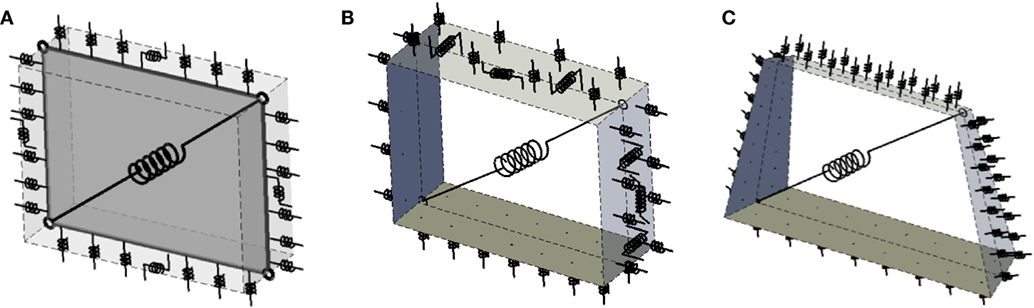
Figure 2. Advances in the mechanical scheme adopted in the proposed macroelement approach: (A) plane element, (B) three-dimensional element, and (C) three-dimensional shell element.
In Figure 2, the mechanical scheme of the macroelement adopted for masonry structure modeling is qualitatively shown together with its evolution. The macroelement is based on a quadrilateral of rigid beams connected by four hinges. One diagonal spring rules the shear diagonal behavior and zero-thickness interfaces, along the four edges, govern the interaction with the adjacent elements. In particular, the element showed in Figure 2A, that is the first basic element proposed in Caliò et al. (2005, 2012a), possesses only the in-plane degrees of freedom and has been conceived for the simulation of the non-linear response of regular plane walls. Its detailed description and main insights are reported in the Section “The Plane Macroelement” for URM buildings and in the Section “The infilled frame structures” for IFS. In Figure 2B, the equivalent scheme of the first proposed three-dimensional element (Pantò et al., 2017a; Pantò, 2007; Caddemi et al., 2014), which implies the addition of the out-of-plane degrees of freedom, is reported. This macroelement is able to account for both the in-plane and out-of-plane behavior of masonry walls, a description of the element with some numerical validations are reported in the Section “The Spatial Three-Dimensional Element.” Finally, in Figure 2C, a further upgrade proposed in Calió et al. (2010), Cannizzaro (2010), and Caddemi et al. (2015) includes the removal of the hypothesis of constant thickness for the element and the adoption of skew interfaces able to properly “follow” a curved geometry layout, thus allowing the modeling of masonry vaults and domes. A brief review of this three-dimensional shell-element and some numerical validations are reported in the Sections “The Shell Element for Modeling Curved Geometry Structures” and “Numerical Examples of Full Scale Structures.”
The Mechanical Characterization
In this sub-paragraph, the original adopted strategy for the mechanical calibration of the macroelements is described. Each macroelement must be representative of the corresponding finite portion of masonry wall, cut out by plane sections located at the edges of the quadrilateral. The formulation here proposed follows a phenomenological description of the mechanical behavior of a masonry portion in which, the zero-thickness interfaces rule the membrane-flexural response and the shear-sliding behavior of adjacent elements, while the in-plane shear element deformability, is related to the angular distortion of the articulated rigid quadrilateral. The mechanical characterization of the zero-thickness interfaces is here performed following a straightforward fiber calibration procedure while the shear element deformability is calibrated through a mechanical equivalence with a reference geometric-consistent continuous model. The interface non-linear links can be distinguished as orthogonal N-links and shear-sliding N-links, as well as diagonal links, Figure 3. In the following, the main steps needed for the calibration procedure are described with reference to each group of non-linear links.
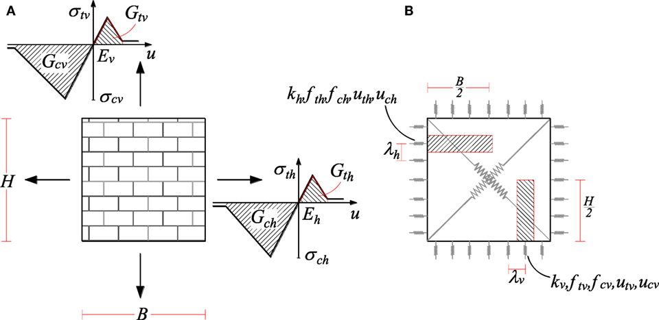
Figure 3. Mechanical characterization of an orthotropic masonry panel: (A) constitutive laws and (B) calibration of the orthogonal N-links (Pantò et al., 2017a).
Calibration of the Non-Linear Links Orthogonal to the Interfaces
The orthogonal non-linear links encompass the mechanical properties of the represented element assuming masonry as an orthotropic homogeneous medium. Each orthogonal link of the mechanical scheme encompasses the non-linear behavior of the corresponding fiber, along a given material direction, Figure 3A. With reference to a regular three-dimensional macroelement, each spring is calibrated assuming that the uniform masonry strip is a homogeneous elasto-plastic material, following the procedure reported in Caliò et al. (2005), which can also consider a post-elastic softening behavior governed by fracture energy values for the tensile and compressive response, Gt and Gc, respectively, and following different post-elastic branches laws.
With reference to a single orthotropic panel, the flexural behavior of the masonry panel is characterized by different mechanical properties along the two fundamental directions. Eh and Ev are the Young’s moduli of the homogenized orthotropic masonry medium; σch, σth and σcv, σtv are the corresponding compressive and tensile maximum stresses, Gch, Gth and Gcv, Gtv are the fracture energies in compression and tension.
Consistently with a fiber calibration approach, the stiffness calibration of the panel is simply obtained by assigning to each link the axial stiffness of the corresponding masonry strip. Each masonry strip is identified by its influence area and the half-dimension of the panel in the direction perpendicular to the interface, Figure 3B. The initial stiffness K, the compressive and tensile yielding strengths, fc and ft, and the corresponding ultimate displacements, uc and ut (under the simplified hypothesis of rectangular shape of the panel and linear softening) of the links relative to the horizontal and vertical interfaces are reported in Table 1 as a function of the mechanical and geometrical properties of the masonry panel. B and H are the length and the height of the panel, λh and λv are the in-plane distances between the springs along the interfaces arranged according to the fundamental directions, and λs is the out-of-plane distance between the rows of springs.
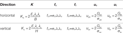
Table 1. Mechanical calibration of the orthogonal N-links for a rectangular panel.
Calibration of the Non-Linear Links along the Interfaces
The non-linear links, lying along the interface and denoted as shear-sliding springs, govern the torsional and shear-sliding behavior along the interfaces. In the discretization here adopted, one single link is considered for the in-plane model (Figure 2A) or three non-linear links have been considered for the spatial models (Figures 2B,C), this being the minimum required to obtain the possible masonry failure modes.
A single in-plane shear-sliding spring governs the in-plane sliding of the element along the interface. The in-plane shear-sliding spring governs the deformations between the elements related to the occurrence of friction sliding along the interfaces. Since the non-linear sliding behavior in correspondence of mortar joints is usually associated with friction phenomena, the in-plane shear-sliding link is calibrated according to a rigid-plastic Mohr–Coulomb law.
The out-of-plane shear deformability is ruled by two parallel springs, which take care of the out-of-plane sliding behavior and the torsional elastic and inelastic response of the connected adjacent panels. The two out-of-plane shear-sliding non-linear links are required to control the out-of-plane sliding mechanisms as well as the torsion around the axis perpendicular to the plane of the interface. Aiming at maintaining a simple fiber calibration approach, the out-of-plane shear deformability of each link, connecting two adjacent panels, is calibrated according to their influence volumes. Referring to two identical adjacent macroelements, with thickness s, width B and height H, shear modulus G, cohesion c, and friction coefficient μs, the calibration procedure is summarized providing the main parameters that govern the mechanical behavior of the sliding links (Table 2).
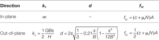
Table 2. Mechanical calibration of the shear-sliding N-links for a rectangular panel.
Once the elastic shear out-of-plane stiffness has been assigned, according to the formulas reported in Table 2, the relative distance d between the two out-of-plane sliding links have to be set according to an equivalence with the corresponding elastic continuum in terms of torsional behavior (Pantò et al., 2017a). Aiming at obtaining a suitable torsional elastic calibration, although maintaining a simplified calibration strategy, the distance d between the two springs is simply obtained considering that the torsional elastic stiffness of the corresponding geometrical consistent continuous model is equivalent to that associated to the discrete system. The yielding strength of each spring is associated with the current contact area A of the interface and to the current axial force N associated with the orthogonal links of the interface.
Calibration of the Diagonal Link
The diagonal spring has the fundamental role of reproducing the diagonal shear failure collapse. This is associated with the loss of the bearing capacity of the masonry panel due to shear and the consequent formation of diagonal cracks along the direction of the principal compressive stresses. Many different yielding criteria can be adopted to account for the shear capacity, which is strongly dependent on the vertical compression stresses in the wall. In the elastic range, the diagonal shear spring is calibrated by imposing an energy equivalence between the articulated quadrilateral, ruled by the diagonal spring and a continuous reference elastic model. The yielding forces are associated with the limits of tensile or compressive stresses in the reference continuous model, while the post-elastic behavior is ruled by a suitable constitutive law. A Mohr–Coulomb law or a Turnsek–Cacovic law can generally be adopted for the constitutive calibration of these non-linear links, although other constitutive laws can also be considered. Further details on the calibration procedures are reported in Cannizzaro (2010).
The Plane Macroelement
The basic element can be described by referring to a simple mechanical representation in which the element is regarded as a plane articulated quadrilateral endowed with along-sides non-linear zero-thickness interfaces (Caliò et al., 2005, 2012a). The mechanical behavior of the element is governed by along-edge non-linear interfaces plus the in-plane deformability of the quadrilateral whose behavior is related to a single degree of freedom only, Figure 2A. To adopt a simple fiber discretization, the zero-thickness interfaces have been conveniently represented in Figure 2A as a regular distribution of non-linear links orthogonal to the interfaces. The shear-sliding behavior along the interfaces, associated with the relative motion in the direction of the interface, can be efficiently described through a single longitudinal spring. The kinematics of the mechanical scheme after a proper calibration procedure of the non-linear links is capable of simulating the main in-plane collapse failure modes of a masonry panel: flexural failure, diagonal shear failure and sliding shear failure. In spite of its simplicity, the assemblage of these elements allows the simulation of the global non-linear response of masonry buildings; however, in this model, the out-of-plane response of the masonry walls is not taken into account.
Each discrete element exhibits three degrees of freedom associated with the in-plane rigid body motion, plus an additional degree of freedom, needed for the description of the in-plane shear deformability. The deformations of the interfaces are associated with the relative motion between corresponding panels; therefore, no further Lagrangian parameter has to be introduced to describe their kinematics. The adopted model has the advantage of interacting with the adjacent elements along the whole perimeter, thus allowing the possibility of using different mesh discretizations as highlighted in the following paragraphs.
To make the simulation of the non-linear behavior of a masonry structure effective, it is necessary to infer the mechanical parameters of the model by means of an equivalence between the masonry material and the reference macro-model characterized by simple but reliable constitutive laws. This equivalence is enforced according to a straightforward fiber calibration procedure, uniquely based on the main mechanical parameters of the masonry (Caliò et al., 2005). It is worth to notice that each macroelement inherits the plane geometrical properties of the corresponding modeled masonry portion. As a consequence, differently from the simplified models based on the equivalent frame element, the model is geometrically consistent to the corresponding modeled masonry wall.
In the following subsection, some significant examples of simple structures are considered to provide a validation of the model. In particular, single masonry panel models, characterized by different geometries and subjected to vertical loads and increasing monotonic horizontal forces, are considered.
Experimental and Numerical Validation of the Plane Element
The first validation is relative to the case of a single panel which was investigated considering a comparison between the proposed approach (Pantò et al., 2015) and an equivalent frame model combined with a fiber section model recently proposed in Raka et al. (2015). The considered example is made of a simple panel restrained at its base and at its top; a two phase analysis is here applied, considering a first force controlled phase with the application of a vertical load and a second displacement controlled phase with an increasing horizontal displacement at the top of the panel. The panel is characterized by the thickness t = 0.6 m, the width w = 3 m, and the height h = 2 m. Displacement controlled pushover analyses were carried out, with imposed increasing displacement at the top of the wall. The adopted mechanical properties are reported in Table 3; however, for this first example, the shear failure is considered inhibited. Even though the model described in Raka et al. (2015) is based on an equivalent frame approach, with regards to the combined flexural–axial behavior, both models are based on a direct fiber section analysis. For this reason, it is expected that the two considered models provide very close results in terms of ultimate load. Several analyses have been performed for different levels of the axial load and in Figure 4A the ultimate bending moment of the base section is reported vs the considered axial load. The capability of the two numerical models to describe the axial–flexural response of a masonry wall section is assessed by comparing the M–N dominium of the base section with that obtained following the closed-form expression reported in the Italian building code (NTC, 2008), whose expression is detailed commented in Lagomarsino et al. (2013). A second example of a single panel is reported in the following. In this case again, a comparison between the proposed approach with the equivalent frame model proposed in Raka et al. (2015) is reported. Unlike the previous case, here the axial, bending, and shear forces interact all together. Figure 4B shows the response of the panel previously described with different axial load ratios, including and neglecting the shear response. For the diagonal shear mechanism, an elasto-plastic constitutive law is here considered, associated with the Turnsek and Cacovic yielding dominium (Turnšek and Čačovič, 1970) ruled by the ultimate shear strength (fv0) in absence of axial compression.
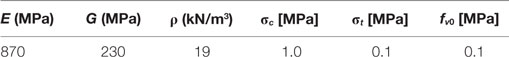
Table 3. Mechanical properties adopted for the masonry.
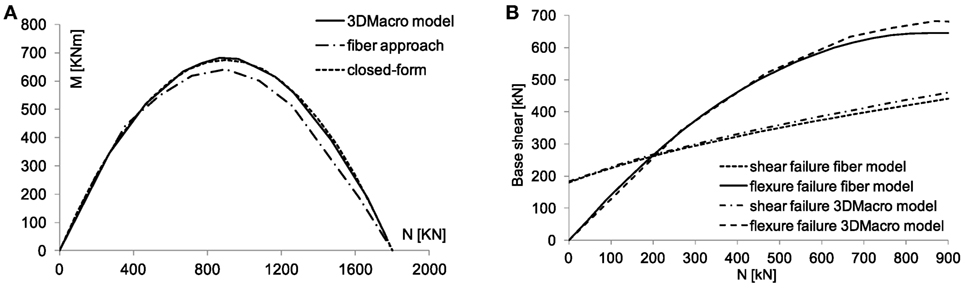
Figure 4. Interaction diagrams: (A) M–N and (B) V–N (Pantò et al., 2015).
In Figure 4B, the ultimate load obtained with the equivalent frame fiber model and the proposed macroelement are compared when either only the flexural or only shear mechanisms are considered, respectively. The two numerical models provide very close results in terms of ultimate loads, and they are consistent with the values suggested by the Italian code (NTC, 2008).
The Infilled Plane Element
The macroelement can also be efficaciously adopted for Infilled Frame Structures (IFS) modeling. In the latter case, a hybrid approach is applied: the surrounding frame is modeled using lumped plasticity beam–column elements while the non-linear response of the infill is modeled by means of the plane macroelement, already described in the previous section. The frame element interacts with the masonry panels by means of non-linear-links distribution along discrete interfaces. Each interface is constituted by n transversal non-linear links and a single longitudinal non-linear link. The flexural interaction between the panel and an adjacent beam is governed by the four degrees of freedom of the beam associated with its two ends and by the n internal degrees of freedom associated with the springs of the interface. For a more accurate evaluation of the non-linear behavior of the frame element, it has been assumed that plastic hinges can occur in each sub-beam element between two non-linear transversal links. This latter assumption provides a reliable frame element model since it is able to embed the occurrence of plastic hinges at different positions and it is consistent with the adopted level of discretization for the infill interface.
The effectiveness of the masonry infill model relies on a suitable choice of the mechanical parameters of the macroelement inferred by an equivalence between the masonry media and a reference continuous model characterized by simple but reliable constitutive laws. This equivalence, as already explained in Section “The Mechanical Characterization,” is based on a straightforward calibration procedure that exploits the main mechanical parameters of the masonry only, according to an orthotropic homogeneous medium, as detailed in Caliò and Pantò (2014). In Figure 5, a typical discretization of a full infill frame (Figure 5A) and an infill frame characterized by a single central opening (Figure 5D) are shown. Figures 5B,E report the corresponding discretization according to a basic mesh of the infill, whereas the representations of Figures 5C,F are relative to a more refined mesh of the infill. This aspect is particularly important in the modeling of infilled frames since it allows a better description of the interaction masonry frame, also in the presence of window or door openings. It is important to notice that the macro-model has the great advantage, compared to the equivalent strut element approaches (Polyakov, 1960), to inherit the plane geometrical properties of the corresponding modeled masonry portion avoiding the introduction of an effective dimension of the element. Despite its mechanical simplicity, the model is able to simulate the main collapse mechanisms that can be involved in infilled frames.
Figure 5. Qualitative representation of full unfilled (A) and opened infilled frame (D) and their modeling by the basic mesh (B,E) and a more refined mesh (C,F) of macroelements (Caliò and Pantò, 2014).
It is worth noticing that the proposed approach is also able to identify combined mechanisms and the simultaneous presence of damage corresponding to different failure modes. To explain this aspect, Figure 6 shows a qualitative representation of the main in-plane failure collapse mechanisms and their simulation by the equivalent macro-model, namely the Corner Crushing mode (Figure 6A), the Diagonal Cracking mode (Figure 6B), the Sliding Shear mode (Figure 6C), and the Frame Failure mode (Figure 6D) (Caliò and Pantò, 2014). The main failure mechanisms typical of IFS are identified comparing them with the corresponding schemes associated with the proposed model, as they were independent collapse mechanisms. In practical experience, it is frequent to have combined mechanisms; however, in this case, they are shown separately to demonstrate the capability of the proposed model of grasping them. For the latter reason, the detachment of the frame from the masonry is shown only in Figure 6A and not in the others (Figures 6B–D). Such mechanisms are reported adopting the convention that the links in compression are reported in blue while the links in tension are reported in red; in addition, plastic hinges occurring at the contouring frame are reported in red.
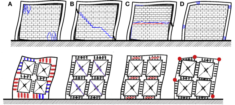
Figure 6. Qualitative representation of the typical collapse mechanisms of infill frame and their simulation by the proposed hybrid FE-macro-model approach. Corner crush (A); diagonal cracking (B), sliding shear (C), and frame failure (D) (Caliò and Pantò, 2014).
Experimental and Numerical Validation of the Infilled Plane Element
In Caliò and Pantò (2014), the proposed model has been validated by simulating the non-linear response of infilled frame prototypes for which experimental results are available from the literature. The results of the experimental program, here re-proposed in Figure 7, are relative to a half scale prototype of non-ductile RC frame fully infilled with brick masonry panels. The prototype was subjected to a horizontal force at the top beam, increased monotonically until the complete collapse of the structure. More details on the geometrical layout and the mechanical characterization of the material are reported in Mehrabi and Shing (1997). Figure 7 shows the numerical results obtained by the macro-model. In particular, the graph in Figure 7A reports the numerical capacity curve of the infilled frame, compared with the experimental response; Figure 7B reports the damage scenario shown by the model at the last step of the analysis, and Figure 7C shows the bending moment distribution on the frame at the same step.
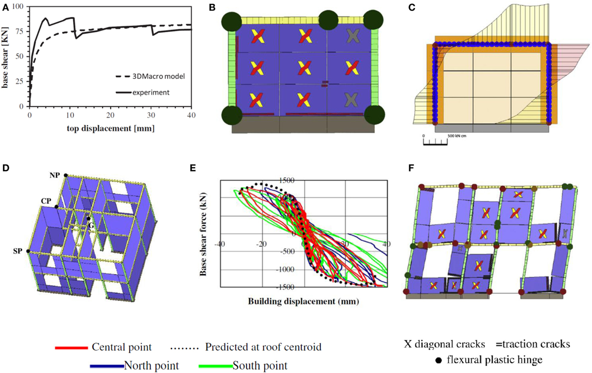
Figure 7. Numerical and experimental lateral response of a prototype of an infilled wall (A,B,C) (Caliò and Pantò, 2014) and a 3D building (D,E,F) (Marques and Lourenço, 2014): (A) capacity curves, (B) damage scenario at collapse, (C) bending moment on the frame at the last step of the analysis, (D) numerical model, (E) comparison in terms of capacity curve, and (F) damage scenario at collapse of the south wall.
A further very important validation of the model, using the software 3DMacro (Caliò et al., 2012b), has been made by Marques and Lourenço (2014) with reference to three-dimensional building prototype. The experimental campaign was carried out at CISMID research center in Peru (Zavala et al., 2004) on a two storey building with irregular plan, representative to a typical family existing residential houses in Peru (Figures 7D–F). The tests were performed under quasi-static cyclic loads, applied through two actuators located at the two slabs, used to induce a constant load pattern to the structure proportional to the building height. In Figure 7E, the comparison between numerical pushover curve (dotted curve) and the experimental results is reported, while Figure 7F shows the damage scenario of the “south” wall at the last step of the analysis, a detailed comparison is reported in Marques and Lourenço (2014).
The Spatial Three-Dimensional Element
A non-trivial spatial extension of the plane macroelement introduced in Section “The Plane Macroelement,” was the extension to a three-dimensional macroelement hereafter described. The element upgrade requires three additional degrees of freedom for the description of the out-of-plane kinematics as well as the introduction of further non-linear links to account for the three-dimensional mechanical behavior of the element. The kinematics of the spatial macroelement is therefore governed by seven degrees of freedom, able to describe the rigid body motions and the element in-plane shear deformability. The interaction of the spatial macroelement with the adjacent elements, or the external supports, is still ruled by zero-thickness interfaces. Each interface is composed, according to a fiber discretization, by m rows of n transversal non-linear springs (N-links), as showed in Figure 8A. The in-plane sliding motion between two continuous panels is governed by a single longitudinal in-plane spring and two additional springs oriented orthogonally to the plane of the element (Figure 8B). The latter two additional springs govern both the out-of-plane sliding mechanisms and the torsion around the axis perpendicular to the plane of the interface. The zero-thickness interface between adjacent elements governs the membrane, bending, sliding, and torsional behaviors, while the in-plane pure shear deformability of the element is controlled by the internal diagonal spring as in the in-plane basic macroelement. The transversal N-links of the interface encompass the axial and the three-dimensional flexural behavior of the panel, assuming for the masonry an equivalent orthotropic homogeneous material. Each transversal N-link represents the non-linear behavior of the corresponding fiber, along a given material direction, see Figure 8A. Those links are calibrated assuming that the masonry strip is a homogeneous inelastic material with a post elastic linear softening behavior governed by two different values of fracture energy, for tension and compression, following the procedure briefly described in Section “The Mechanical Characterization” and reported in detail in Cannizzaro and Lourenço (2017). The calibration procedures for both diagonal and in-plane sliding spring follow the same strategy already adopted for the plane macroelement (Caliò et al., 2012a).
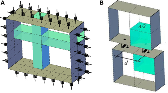
Figure 8. Two generic transversal N-links and the corresponding fiber representations (A); reference masonry volume associated with each out-of-plane longitudinal N-link (B).
The two longitudinal out-of-plane links of the interfaces are calibrated to reproduce the elastic out-of-plane shear deformation of the influence masonry volumes associated with the link, according to the shear modulus G of the masonry (Figure 8B). Once the elastic shear out-of-plane stiffness has been calibrated, the relative distance d between the two springs (Figure 8B) is set according to a criterion which guarantees the retrieval of the elastic torsion stiffness associated with the reference continuous volumes, as better highlighted in Table 2. More details on this calibration procedure can be found in Pantò et al. (2017a).
Experimental and Numerical Validation of the Spatial Element
An extensive numerical validation of the model has been recently carried out in Pantò et al. (2017a) by considering masonry panels loaded out-of-plane with different geometries and boundary conditions. The results obtained by the macro model have been compared with experimental and numerical results already available in the literature. The first application here presented consists of hollow concrete block masonry panels, tested at the McMaster University (Gazzola et al., 1985). All the investigated panels have the same thickness (100 mm) and height (2,800 mm) but different geometric ratios (between width and height of the panels): 1.2, 1.8, and 2.1. Three of the panels (WI, WII, and WIII) were fixed by simply vertical supports in all edges, while the last one (WF), characterized by a geometric ratio equal to 1.8, was fixed along three edges while the upper horizontal edge was free. All the panels were loaded until failure with increasing out-of-plane uniform pressure p. In Figures 9A,B, the results relative to the WI and WF panels are reported in terms of the lateral capacity, and two representations of the damage scenario at the peak load and at the final collapse mechanisms after the softening branch are reported. To provide an effective representation of the damage, the deformed shape is integrated with a gray scale representation, which indicates the normal plastic deformations on the interfaces, while the in-plane and out-of-plane sliding motion is represented by the red lines.
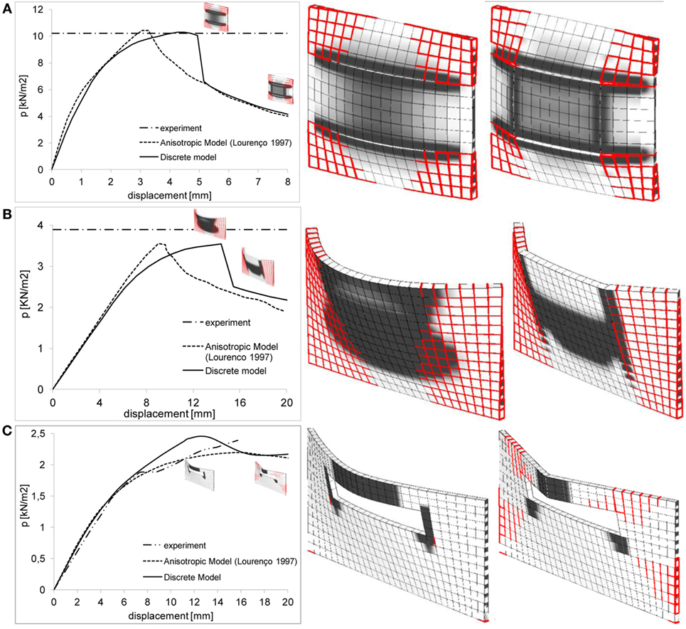
Figure 9. (A) Four (WI), (B) three edges restrained full panel (WF), and (C) windows opened panel (SB3 specimen) (Pantò et al., 2017b): numerical and experimental capacity curves (left side), damage scenario at the peak load (center), and collapse mechanism at the last step of the analysis (right side).
The second investigation, here considered, is relative to a solid clay brick masonry with openings (specimen from SB1 to SB5), carried out by Chong et al. (1995) to evaluate the ability of the investigated 3D macro-model to reproduce the behavior of masonry walls, also in presence of openings and for different masonry typologies. All the panels were characterized by the same dimensions (5,600 mm × 2,475 mm × 100 mm) but different dimension of central opening. The tests were performed by providing a full restrained support at the base, two simply hinged supports at the vertical edges, and the top horizontal edge free.
In Figure 9C the force–displacement curve obtained by the discrete macro-model approach, for the SB3 panel, is compared with the experimental test results (Chong et al., 1995) (dash dot line) and with numerical simulations obtained by non-linear finite element analyses performed by Lourenço (1997). Several cases, which included both windows and door opening typologies, are reported in Pantò et al. (2017a), where a very good agreement between numerical and the experimental curves was observed for all the investigated panels. Also the failure mechanisms obtained by the macro-model numerical simulations appear to be consistent with the experimental observations.
The Shell Element for Modeling Curved Geometry Structures
The model presented in the Section “The Spatial Three-Dimensional Element” (Pantò et al., 2017a) allows the simulation of the contemporary action of in-plane and out-of-plane forces on masonry walls based on a regular geometry. According to this model, each element belongs to a structural plane, its shape is rectangular, and characterized by a constant thickness. To overcome these geometrical limits and to allow modeling more complex geometrical layouts, a further extension of the model was proposed in Cannizzaro (2010) and Caddemi et al. (2015). This extension was motivated by the need of applying the macroelement approach to historical and monumental masonry structures, and in particular to two main structural typologies as follows:
1. plane structural elements with an irregular geometry, such as, walls with irregular elements or arches, for which a mesh of rectangular element cannot be adopted;
2. curved shell masonry structures, as, for example, vaults and domes.
The study of such structural typologies is further complicated by the complex geometry, which connotes them. The corresponding upgrades of the macroelement were needed since the static and dynamic equilibrium of curved masonry structures is mainly guaranteed by their shapes. The most significant novelties of the improved element can be summarized in the following features:
i. interfaces are no longer orthogonal to the plane of the element, thus allowing to follow the curved geometry of the structure;
ii. the thickness can be linearly variable at each interface, thus allowing to consider four independent thicknesses in the four nodes of each element;
iii. the shape of the element can be represented by a generic quadrangular element, thus removing the geometrical restriction of the rectangular shape.
A qualitative representation of this upgraded element is reported in Figure 2C. In spite of the complications due to the curved geometry, the model still keeps the original computational effort since its kinematics is ruled by seven degrees of freedom (six rigid body motion degrees of freedom and one associated with the in-plane shear deformability). The upgrades of the element, shortly described in the following, imply substantial modifications of the calibration procedure to account for the more complex geometry of the element.
Regarding the transversal springs (N-links) of the inter-element interfaces, which are still calibrated according to a fiber approach, the upgraded geometry implies that each link corresponds to a prismatic fiber, whose cross-sectional area varies with a parabolic trend. The grid of the fibers’ projections on each interface is no more regular to account for the geometric distortion according to an isoparametric correspondence between spatial coordinates and intrinsic regular coordinate system. The non-linear sliding links are three in each interface, just like for the regular spatial model: one link along the axis of the interface (in-plane sliding link) and two orthogonal to the axis and still lying on the plane of the interface (out-of-plane sliding links). The calibration strategy follows the same philosophy of the previous spatial regular model. Since those links have to simulate the occurrence of sliding along the bed joints, their non-linear behavior is closely affected by friction phenomena; for this reason the yielding domain accounts for the influence of the normal force acting on the interface. This calibration approach strictly follows the procedure employed for the regular spatial element; however, it accounts for the more complex geometry of the curved element in terms of irregular shape of the interface. In the subdivision of an arbitrary shell into flat elements, both triangular (Triang) and quadrilateral (Quad) elements should generally be used (Figure 10). The triangular elements are assumed to be rigid in their own plane and are therefore characterized by six degrees of freedom only.
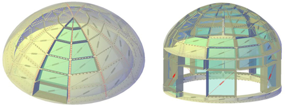
Figure 10. Qualitative examples of subdivision of curve-shaped masonry structures through the proposed macroelement strategy (Cannizzaro, 2010; Caddemi et al., 2015).
A detailed description of the mechanical characterization of this non-trivial shell discrete element is outside the purpose of the present paper that is oriented to a methodological description of this computationally effective approach aiming at demonstrating its suitability for practical applications devoted to the seismic assessment of existing masonry structures; in particular, the discrete macroelement here described is mainly devoted to the numerical simulation of the non-linear response of historical and monumental structures. More details on the calibration procedures can be found in Cannizzaro (2010).
Experimental and Numerical Validation of the Shell Element
The applications reported in the following aim at validating the model through a comparison with experimental and numerical results. The case here reported is relative to a brick masonry spherical dome with a central hole tested in 2006 by Foraboschi (2006). The dome was subjected to a vertical load along the edge of the central hole. Details on the experimental layout and on the mechanical properties can be found in Foraboschi (2006).
The numerical model implemented to simulate the experimental tests consists of 544 QUAD (17 along meridians and 32 along parallels) which correspond to a total number of degrees of freedom equal to 3,808. Regarding the membrane fiber discretization, a maximum distance of the orthogonal non-linear links equal to 5 cm along the parallels and 1.5 cm through the thickness of the dome have been set, respectively. In the performed non-linear static analysis, the model has been subjected firstly to its self-weight, then to the external vertical load applied on the annulus of quadrilateral elements sited around the hole.
The mechanical properties employed in the numerical simulations, reported in Table 4, have been deduced by the simulations already reported in the literature (Milani et al., 2008; Milani and Tralli, 2012). The Elastic properties of the masonry are represented by the Young’s modulus (E) and the shear modulus (G). The sliding shear failure is ruled by the cohesion (c) and the friction factor (μs). The diagonal shear failure is considered elastic.
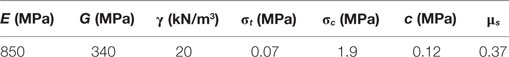
Table 4. Mechanical properties adopted for the numerical model of the hemispherical dome.
In Figure 11, the results of the non-linear static analyses, expressed in terms of deformed shape and damage pattern at collapse, have been compared to those already available in the literature. Namely, Figure 11C reports the vertical top displacement as a function of the vertical load. The proposed model correctly predicts the initial stiffness and the ultimate load of the structure, and it is in good agreement with the available numerical results throughout all the phases of the experiment.
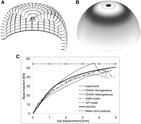
Figure 11. Hemispherical dome (Caddemi et al., 2015): (A) failure mechanism represented in half dome, (B) damage inelastic distribution expressed in gray scale, and (C) load displacement curves.
In Figures 11A,B, the failure mechanism and the corresponding damage scenario at the incipient collapse condition, obtained by the numerical model implemented in HiStrA (Caliò et al., 2015), are reported. More details of the comparison can be found in Caddemi et al. (2015).
Numerical Examples of Full Scale Structures
Numerical and experimental validations of the proposed approach with reference to full scale structures can be found in Pantò et al. (2016, 2017b). Here some results reported in Pantò et al. (2017b) are recalled with the aim of showing a detailed and critical numerical comparison between the proposed discrete modeling approach and a refined finite element approach on a single-nave church, severely damaged by the Italian 2012 earthquake, which was analyzed by using both procedures. This numerical validation was performed both in the linear and non-linear fields through linear modal analysis and non-linear pushover analyses. The example under consideration is the St. Venerio church located in Reggiolo (Emilia Romagna region, Italy), 20 km far from the epicenter of the earthquake that struck the Emilia Romagna Italian region on 2012 May 29th. All the geometrical and mechanical details of the church can be found in Pantò et al. (2017b). The church is entirely built with clay bricks and lime mortar, often used in the nearby area for similar historic chapels.
The 2012 Emilia earthquake caused severe damages to the church: the timber roof and the main vault partially collapsed, a partial overturning mechanism of the main façade and the apse occurred and out-of-plane and in-plane damages were observed in the façades (Giresini et al., 2014).
The non-linear finite element model of the entire church was implemented in ABAQUS CAE 6.12 according to the Concrete Damaged Plasticity material (Abaqus 2014) (Giresini et al., 2014). The discrete macroelement model was developed by using the software HiStrA (Caliò et al., 2015).
The mesh discretization of the discrete model has been chosen to obtain a parsimonious model of the entire church, characterized by a reduced number of computational elements and degrees of freedom, compared to the finite element model. The FEM model possesses 114,936 degrees of freedom whereas the HiStrA model is characterized by 15,060 degrees of freedom.
Linear Field Validation
The validation in the linear elastic field was performed by comparing the eigen-properties provided by the two models.
The first 20 periods with the effective mass ratios and cumulated mass, along the longitudinal (X) and the transversal (Y) directions, are compared in Pantò et al. (2017b). Here, the first two fundamental modes of vibration of the continuous model and the discrete model are reported in Figure 12.
Figure 12. Comparison between the first two fundamental mode shapes between the ABAQUS and the HiStrA models (Pantò et al., 2017b).
A very good agreement can be observed between the two models, both in terms of natural frequencies and mode shapes of vibration. These results allow to conclude that the proposed discrete macro-model is able to simulate the linear dynamic properties of the structure with a significant lower computation effort with respect to the FEM model.
Non-Linear Field Validation
The parameters that govern the non-linear mechanical behavior of the masonry were assigned coherently in the two models. Preliminary tests on isolated masonry walls, loaded in their plane, have been performed to verify the correspondence between the discrete and the finite element models and with the aim of investigating the sensitivity of the non-linear response of the two models on the variability of the main mechanical parameters (Pantò et al., 2017b).
The results reported in Figure 13 show the collapse mechanism of the discrete model subjected to non-linear static analyses. Namely, Figures 13A,B report the collapse scenarios related to the longitudinal directions, whereas Figure 13C is relative to the transversal direction, in this latter case, a single analysis has been performed due to the symmetry of the model. In the pictures, the damage distributions are also represented in terms of cumulative normal plastic deformations along the interfaces according to a gray scale representation.
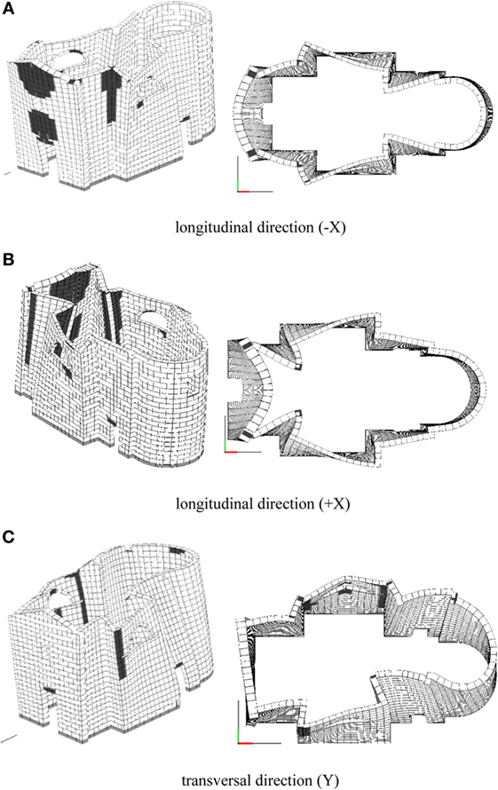
Figure 13. Deformed shape and damage pattern at the peak load step of the analysis—HiStrA model (Pantò et al., 2017b). (A) Longitudinal direction (−X). (B) Longitudinal direction (+X). (C) Transversal direction (Y).
The damage distributions obtained by means of the discrete model are consistent to the results obtained by the continuous FEM model (Pantò et al., 2017b). Both models provide results consistent to the typical collapse mechanisms of such structures when subjected to earthquake loads. Figure 14 shows the collapse mechanisms obtained by the discrete model when the residual strength of the system has been reached. The final collapse of the façade is characterized by the complete detachment of the upper part at the connections with the orthogonal walls, when subjected to out-of-plane action forward directed. On the contrary, when the model is subjected to inward forces, a central vertical hinge characterizes the collapse mechanism of the main façade. It is worth to notice that the discrete element modeling approach returns a complete set of collapse mechanisms, where the well known typical façade mechanisms of monumental structures, characterized by an high rigid body component, are recognizable.
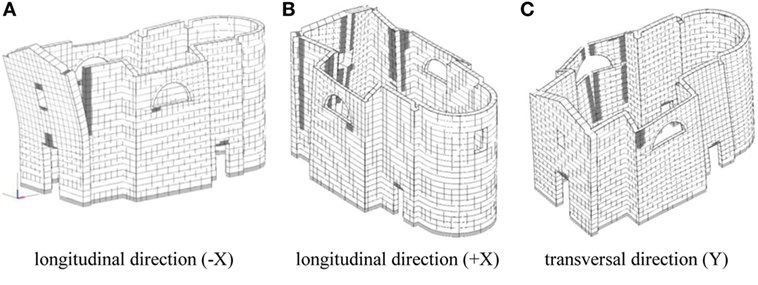
Figure 14. Deformed shape and damage pattern at the last step of analysis—HiStrA model (Pantò et al., 2017b). (A) Longitudinal direction (−X). (B) Longitudinal direction (+X). (C) Transversal direction (Y).
The results in terms of pushover curves expressed with the monitored displacement, as depicted in Figure 15, are reported in Pantò et al. (2017b). Here, the capacity curves relative to the portion of the perimeter walls that exhibits the maximum displacement are compared, that is, the top of the tympanum for the analyses in the longitudinal direction and the top of the lateral wall in correspondence of the semicircular window for the analysis in the transversal direction.
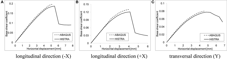
Figure 15. Comparisons between the HiStrA and the ABAQUS in terms of capacity curves. (A) Longitudinal direction (−X). (B) Longitudinal direction (+X). (C) Transversal direction (Y).
An excellent correspondence is recognized both in terms of initial stiffness and maximum capacity. The analyses performed in the HiStrA software are also characterized by the presence of the softening branch providing further information in terms of post peak behavior.
Summary and Conclusion
In this paper, a numerical strategy aiming at simulating the non-linear behavior of masonry structures is presented. The proposed numerical model, which belongs to the framework of the simplified models, is based on a simple mechanical scheme that consists of a hinged quadrilateral, endowed with a diagonal link to govern the in-plane diagonal shear behavior, and contouring interfaces that rule the interaction with contiguous elements.
The proposed approach appears to be a fair compromise between oversimplified models (limit analysis or equivalent frame models) and accurate models based on cumbersome strategies, which require an expert interpretation of the results. The basic model, originally conceived for the simulation of masonry walls loaded in their own plane was repeatedly upgraded, progressively increasing the structural typologies that the proposed strategy is able to model. In particular, within the scope of the numerical simulation of ordinary buildings with box behavior (the out-of-plane behavior is considered inhibited), interaction with frames contouring a masonry panel was enabled, thus allowing the numerical simulation of both unreinforced masonry structures (URM) and infilled masonry structures (IFS).
Aiming at the numerical modeling of historical masonry structures (HMS), two further upgrades were considered. First, the out-of-plane degrees of freedom were enabled to assess the out-of-plane behavior of masonry walls; then, a further improvement allowed simulating masonry structures with a curved geometry. Finally, by ruling the interaction between structural elements in correspondence of their intersections, full non-linear simulations of large historical masonry constructions were performed. The progressive improvements were obtained simply extending the calibration procedure of the links according to the different peculiarities of the model at the various stages of complexity. However, the philosophy of the model was kept the same for all the considered advances of the model, that is, the calibration is always straightforward and based on the same concepts.
Several validations of the model were presented consistently with each of the described stage. The results show that the proposed strategy appears to be reliable in all the considered cases and that it represents an original approach to the non-linear assessment of ordinary masonry buildings, historical and monumental structures.
Author Contributions
IC: substantial contributions to the conception or design of the work; or the acquisition, analysis, or interpretation of data for the work; drafting the work or revising it critically for important intellectual content; final approval of the version to be published; and agreement to be accountable for all aspects of the work in ensuring that questions related to the accuracy or integrity of any part of the work are appropriately investigated and resolved. SC: substantial contributions to the conception or design of the work; or the acquisition, analysis, or interpretation of data for the work; revising critically the work for important intellectual content; and agreement to be accountable for all aspects of the work in ensuring that questions related to the accuracy or integrity of any part of the work are appropriately investigated and resolved. BP and FC: substantial contributions to the conception or design of the work; or the acquisition, analysis, or interpretation of data for the work; and drafting the work or revising it critically for important intellectual content.
Conflict of Interest Statement
The authors declare that the research was conducted in the absence of any commercial or financial relationships that could be construed as a potential conflict of interest.
References
Anthoine, A. (1997). Homogenisation of periodic masonry: plane stress, generalised plane strain or 3D modelling? Commun. Numer. Methods Eng. 13, 319–326. doi: 10.1002/(SICI)1099-0887(199705)13:5<319::AID-CNM55>3.3.CO;2-J
Araujo, A., Lourenço, P. B., Oliveira, D., and Leite, J. (2012). Seismic assessment of St James Church by means of pushover analysis – before and after the New Zealand earthquake. Open Civil Eng. J. 6, 160–172. doi:10.2174/1874149501206010160
Asteris, P. G., Antoniou, S. T., Sophianopoulos, D., and Chrysostomou, C. Z. (2011). Mathematical macromodeling of infilled frames: state of the art. J. Struct. Eng. 137, 1508–1517. doi:10.1061/(ASCE)ST.1943-541X.0000384
Asteris, P. G., Chronopoulos, M. P., Chrysostomou, C. Z., Varum, H., Plevris, V., Kyriakides, N., et al. (2014). Seismic vulnerability assessment of historical masonry structural systems. Eng. Struct. 62-63, 118–134. doi:10.1016/j.engstruct.2014.01.031
Barbieri, G., Biolzi, L., Bocciarelli, M., Fregonese, L., and Frigeri, A. (2013). Assessing the seismic vulnerability of a historical building. Eng. Struct. 57, 523–535. doi:10.1016/j.engstruct.2013.09.045
Berto, L., Saetta, A., Scotta, R., and Vitaliani, R. (2002). Orthotropic damage model for masonry structures. Int. J. Numer. Methods Eng. 55, 127–157. doi:10.1002/nme.495
Betti, M., and Vignoli, A. (2008). Assessment of seismic resistance of a basilica-type church under earthquake loading: modelling and analysis. Adv. Eng. Soft. 39, 258–283. doi:10.1016/j.advengsoft.2007.01.004
Betti, M., and Vignoli, A. (2011). Numerical assessment of the static and seismic behaviour of the basilica of Santa Maria all’Impruneta (Italy). Constr. Build. Mater. 25, 4308–4324. doi:10.1016/j.conbuildmat.2010.12.028
Braga, F., Liberatore, D., and Spera, G. (1998). “A computer program for the seismic analysis of complex masonry buildings,” in Computer Methods in Structural Masonry, Vol. 4, eds G. N. Pande, J. Middleton, and B. Kralj (London: E & FN Spon), 309–316.
Brenchich, G., Gambarotta, L., and Lagomarsino, S. (1998). “A macroelement approach to the three-dimensional seismic analysis of masonry buildings,” in Proceedings of 11th European Conference on Earthquake Engineering (Paris, Rotterdam: A. A. Balkema), 602.
Caddemi, S., Caliò, I., Cannizzaro, F., Occhipinti, G., and Pantò, B. (2015). “A parsimonious discrete model for the seismic assessment of monumental structures,” in Proceedings of the Fifteenth International Conference on Civil, Structural and Environmental Engineering Computing, eds J. Kruis, Y. Tsompanakis, and B. H. V. Topping (Stirlingshire, UK: Civil-Comp Press), Paper 82.
Caddemi, S., Caliò, I., Cannizzaro, F., and Pantò, B. (2013). “A new computational strategy for the seismic assessment of infilled frame structures,” in Proceedings of the Fourteenth International Conference on Civil, Structural and Environmental Engineering Computing, eds B. H. V. Topping and P. Iványi (Stirlingshire, UK: Civil-Comp Press), Paper 77.
Caddemi, S., Caliò, I., Cannizzaro, F., and Pantò, B. (2014). “The seismic assessment of historical masonry structures,” in Proceedings of the Twelfth International Conference on Computational Structures Technology, eds B. H. V. Topping and P. Iványi (Stirlingshire, UK: Civil-Comp Press), Paper 78.
Caliò, I., Cannizzaro, F., D’Amore, E., Marletta, M., and Pantò, B. (2008). “A new discrete-element approach for the assessment of the seismic resistance of composite reinforced concrete-masonry buildings,” in AIP Conference Proceedings, 1020 (PART 1); 2008 Jun 24–27; Reggio Calabria, p. 832–839.
Calió, I., Cannizzaro, F., and Marletta, M. (2010). A discrete element for modeling masonry vaults. Adv. Mater. Res. 133-134, 447–452. doi:10.4028/www.scientific.net/AMR.133-134.447
Caliò, I., Cannizzaro, F., Pantò, B., and Rapicavoli, D. (2015). “HiStrA (historical structure analysis),” in HISTRA s.r.l (Catania, Italy). Release 17.2.3; April 2015. Available at: http://www.grupposismica.it
Caliò, I., Marletta, M., and Pantò, B. (2005). “A simplified model for the evaluation of the seismic behaviour of masonry buildings,” in Proceedings of the Tenth International Conference on Civil, Structural and Environmental Engineering Computing, ed. B. H. V. Topping (Stirlingshire: Civil-Comp Press), 195.
Caliò, I., Marletta, M., and Pantò, B. (2012a). A new discrete element model for the evaluation of the seismic behaviour of unreinforced masonry buildings. Eng. Struct. 40, 327–338. doi:10.1016/j.engstruct.2012.02.039
Caliò, I., Cannizzaro, F., Marletta, M., and Pantò, B. (2012b). 3DMacro: A 3D Computer Program for the Seismic Assessment of Masonry Buildings. Catania, Italy: Gruppo Sismica s.r.l.
Caliò, I., and Pantò, B. (2014). A macro-element modelling approach of infilled frame structures. Comput. Struct. 143, 91–107. doi:10.1016/j.compstruc.2014.07.008
Cannizzaro, F. (2010). The Seismic Behavior of Historical Buildings: A Macro-Element Approach. PhD Thesis in Structural Engineering, in Italian. University of Catania.
Cannizzaro, F., and Lourenço, P. B. (2017). Simulation of shake table tests on out-of-plane masonry buildings. Part (VI): discrete element approach. Int. J. Archit. Herit. 11, 125–142.
Casolo, S., and Peña, F. (2007). Rigid element model for in-plane dynamics of masonry walls considering hysteretic behaviour and damage. Earthq. Eng. Struct. D. 36, 1029–1048. doi:10.1002/eqe.670
Casolo, S., and Sanjust, C. A. (2009). Seismic analysis and strengthening design of a masonry monument by a rigid body spring model: the “Maniace Castle” of Syracuse. Eng. Struct. 31, 1447–1459. doi:10.1016/j.engstruct.2009.02.030
Chen, S. Y., Moon, F. L., and Yi, T. (2008). A macroelement for the nonlinear analysis of in-plane unreinforced masonry piers. Eng. Struct. 30, 2242–2252. doi:10.1016/j.engstruct.2007.12.001
Chong, V. L., Southcombe, C., and May, I. M. (1995). “The behavior of laterally loaded masonry panels with openings,” in Proceeding of the Fourth. International Masonry Conference (London), 178–182.
D’Asdia, P., and Viskovic, A. (1995). Analyses of a masonry wall subjected to horizontal actions on its plane, employing a non-linear procedure using changing shape finite elements. Trans. Modell. Simul. 10, 519–526.
Foraboschi, P. (2006). “Masonry structures externally reinforced with FRP strips: tests at the collapse [in Italian],” in Proceedings of I Convegno Nazionale Sperimentazioni su Materiali e Strutture (Venice).
Gambarotta, L., and Lagomarsino, S. (1997). Damage models for the seismic response of brick masonry shear walls. Part II: the continuum model and its applications. Earthq. Eng. Struct. D. 26, 441–462. doi:10.1002/(SICI)1096-9845(199704)26:4<423::AID-EQE650>3.0.CO;2-#
Gazzola, E. A., Drysdale, R. G., and Essawy, A. S. (1985). “Bending of concrete masonry walls at different angles to the bed joints,” in Proceedings of the Third North America Masonry Conference (Arlington, TX, USA), Paper 27.
Giresini, L., Butenweg, C., Andreini, M., De Falco, A., and Sassu, M. (2014). “Macro-elements identification in historic chapels: the case of St. Venerio chapel in Reggiolo – Emilia Romagna,” in Proceedings of the International Conference on Structural Analysis of Historical Constructions (SAHC) (Mexico City, Mexico).
Kappos, A. J., Penelis, G. G., and Drakopoulos, C. G. (2002). Evaluation of simplified models for lateral load analysis of unreinforced masonry buildings. J. Struct. Eng. 128, 890–897. doi:10.1061/(ASCE)0733-9445(2002)128:7(890)
Lagomarsino, S., Penna, A., Galasco, A., and Cattari, S. (2013). TREMURI program: an equivalent frame model for the nonlinear seismic analysis of masonry buildings. Eng. Struct. 56, 1787–1799. doi:10.1016/j.engstruct.2013.08.002
Lofti, H. R., and Shing, P. B. (1994). Interface model applied to fracture of masonry structures. J. Struct. Eng. 120, 63–80. doi:10.1061/(ASCE)0733-9445(1994)120:1(63)
Lourenço, P. B. (1997). “An anisotropic macro-model for masonry plates and shells: implementation and validation,” in Report n° 03.21.1.3.07 (Delft: Technical University of Delft and Minho University), 70.
Lourenço, P. B. (2002). Computations on historic masonry structures. Solid. Mech. Appl. 4, 301–319. doi:10.1002/pse.120
Lourenço, P. B., Nuno Mendes, A. T., and Ramos, L. F. (2012). Seismic performance of the St. George of the Latins church: lessons learned from studying masonry ruins. Eng. Struct. 40, 501–518. doi:10.1016/j.engstruct.2012.03.003
Lourenço, P. B., and Rots, J. G. (1997). A multi-surface interface model for the analysis of masonry structures. J. Eng. Mech. 123, 660–668. doi:10.1061/(ASCE)0733-9399(1997)123:7(660)
Lourenço, P. B., Rots, J. G., and Blaauwendraad, J. (1998). Continuum model for masonry: parameter estimation and validation. J. Struct. Eng. 124, 642–652. doi:10.1061/(ASCE)0733-9445(1998)124:6(642)
Macorini, L., and Izzuddin, B. A. (2011). A non-linear interface element for 3D mesoscale analysis of brick-masonry structures. Int. J. Numer. Methods Eng. 85, 1584–1608. doi:10.1002/nme.3046
Magenes, G., and La Fontana, A. (1998). Simplified nonlinear seismic analysis of masonry buildings. Proc. Br. Masonry Soc. 8, 190–195.
Marques, R., and Lourenço, P. B. (2011). Possibilities and comparison of structural component models for the seismic assessment of modern unreinforced masonry buildings. Comput. Struct. 89, 2079–2091. doi:10.1016/j.compstruc.2011.05.021
Marques, R., and Lourenço, P. B. (2014). Unreinforced and confined masonry buildings in seismic regions: validation of macro-element models and cost analysis. Eng. Struct. 64, 52–67. doi:10.1016/j.engstruct.2014.01.014
Mehrabi, A. B., and Shing, P. B. (1997). Finite element modeling of masonry-infilled RC frames. J. Struct. Eng. 123, 604–613. doi:10.1061/(ASCE)0733-9445(1997)123:5(604)
Mele, E., De Luca, A., and Giordano, A. (2003). Modelling and analysis of a basilica under earthquake loading. J. Cult. Herit. 4, 355–367. doi:10.1016/j.culher.2003.03.002
Milani, E., Milani, G., and Tralli, A. (2008). Limit analysis of masonry vaults by means of curved shell finite elements and homogenization. Int. J. Solids Struct. 45, 5258–5288. doi:10.1016/j.ijsolstr.2008.05.019
Milani, G., and Tralli, A. (2012). A simple meso-macro model based on SQP for the non-linear analysis of masonry double curvature structures. Int. J. Solids Struct. 46, 808–834. doi:10.1016/j.ijsolstr.2011.12.001
Milani, G., and Valente, M. (2015). Failure analysis of seven masonry churches severely damaged during the 2012 Emilia-Romagna (Italy) earthquake: non-linear dynamic analyses vs conventional static approaches. Eng. Fail. Anal. 54, 13–56. doi:10.1016/j.engfailanal.2015.03.016
NTC. (2008). Decreto Ministeriale. Norme tecniche per le costruzioni. Ministry of Infrastructures and Transportations. G.U. S.O. n.30 on 4/2/2008;2008 [in Italian].
Pantò, B. (2007). The Seismic Modeling of Masonry Structure, An Innovative Macro-Element Approach. PhD Thesis in Structural Engineering, in Italian. Catania: University of Catania.
Pantò, B., Cannizzaro, F., Caddemi, S., and Caliò, I. (2016). 3D macro-element modelling approach for seismic assessment of historical masonry churches. Adv. Eng. Softw. 97, 40–59. doi:10.1016/j.advengsoft.2016.02.009
Pantò, B., Cannizzaro, F., Caliò, I., and Lourenço, P. B. (2017a). Numerical and experimental validation of a 3D macro-model element method for the in-plane and out-of-plane behaviour of unreinforced masonry walls. Int. J. Archit. Herit. doi:10.1080/15583058.2017.1325539
Pantò, B., Giresini, L., Sassu, M., and Caliò, I. (2017b). Non-linear modeling of masonry churches through a discrete macro-element approach. Earthq. Struct. 12, 223–236. doi:10.12989/eas.2017.12.2.223
Pantò, B., Raka, E., Cannizzaro, F., Camata, G., Caddemi, S., Spacone, E., et al. (2015). “Numerical macro-modeling of unreinforced masonry structures: a critical appraisal,” in Proceedings of the Fifteenth International Conference on Civil, Structural and Environmental Engineering Computing, eds B. H. V. Topping and P. Iványi (Stirlingshire: Civil-Comp Press).
Polyakov, S. V. (1960). “On the interaction between masonry filler walls and enclosing frame when loading in the plane of the wall,” in Translation in Earthquake Engineering (San Francisco: Earthquake Engineering Research Institute), 36–42.
Raka, E., Spacone, E., Sepe, V., and Camata, G. (2015). Advanced frame element for seismic analysis of masonry structures: model formulation and validation. Earthq. Eng. Struct. D. 44, 2489–2506. doi:10.1002/eqe.2594
Turnšek, V., and Čačovič, F. (1970). “Some experimental results on the strength of brick masonry walls,” in Proceedings of the 2nd International Brick & Block Masonry Conference (Stoke-on-Trent), 149–156.
Keywords: macroelement, discrete element, unreinforced masonry, historical masonry structures, cultural heritage protection, infilled frame structures, 3DMacro software, HiStrA software
Citation: Caddemi S, Caliò I, Cannizzaro F and Pantò B (2017) New Frontiers on Seismic Modeling of Masonry Structures. Front. Built Environ. 3:39. doi: 10.3389/fbuil.2017.00039
Received: 03 March 2017; Accepted: 27 June 2017;
Published: 24 July 2017
Edited by:
Panagiotis G. Asteris, School of Pedagogical & Technological Education, GreeceReviewed by:
Amin Mohebkhah, Malayer University, IranPutul Haldar, Indian Institute of Technology Ropar, India
Anaxagoras Elenas, Democritus University of Thrace, Greece
Constantinos Repapis, Piraeus University of Applied Sciences, Greece
Copyright: © 2017 Caddemi, Caliò, Cannizzaro and Pantò. This is an open-access article distributed under the terms of the Creative Commons Attribution License (CC BY). The use, distribution or reproduction in other forums is permitted, provided the original author(s) or licensor are credited and that the original publication in this journal is cited, in accordance with accepted academic practice. No use, distribution or reproduction is permitted which does not comply with these terms.
*Correspondence: Bartolomeo Pantò, bpanto@dica.unict.it