Lateral Load-Resisting System Using Mass Timber Panel for High-Rise Buildings
 Zhiyong Chen
 Ying-Hei Chui
- 1Advanced Building Systems Department, FPInnovations, Vancouver, BC, Canada
- 2Department of Civil and Environmental Engineering, University of Alberta, Edmonton, AB, Canada
As global interest in using engineered wood products in tall buildings intensifies due to the “green” credential of wood, it is expected that more tall wood buildings will be designed and constructed in the coming years. This, however, brings new challenges to the designers. One of the major challenges is how to design lateral load-resisting systems (LLRSs) with sufficient stiffness, strength, and ductility to resist strong wind and earthquakes. In this study, an LLRS using mass timber panel on a stiff podium was developed for high-rise buildings in accordance with capacity-based design principle. The LLRS comprises eight shear walls with a core in the center of the building, which was constructed with structural composite lumber and connected with dowel-type connections and wood–steel composite system. The main energy dissipating mechanism of the LLRS was detailed to be located at the panel-to-panel interface. This LLRS was implemented in the design of a hypothetical 20-storey building. A finite element (FE) model of the building was developed using general-purpose FE software, ABAQUS. The wind-induced and seismic response of the building model was investigated by performing linear static and non-linear dynamic analyses. The analysis results showed that the proposed LLRS using mass timber was suitable for high-rise buildings. This study provided a valuable insight into the structural performance of LLRS constructed with mass timber panels as a viable option to steel and concrete for high-rise buildings.
Introduction
In the past century, with the introduction of building codes around the world, wood buildings are usually restricted to a maximum of three to six storeys. Nowadays, wood is attracting a lot of global attention for use in mid- and high-rise buildings, due to its low carbon footprint and fast construction time. Consequently, several contemporary high-rise wood buildings have been constructed around the world over the last 10 years. For example, the tallest wood building in the world is currently the Treet building in Bergen, Norway, which is 14-storey high using glulam truss as the lateral load-resisting system (LLRS) with cross-laminated timber (CLT). An 18-storey student residence building is currently under construction in Vancouver, Canada. It will be the tallest one of its kind once its construction is completed. Karacabeyli and Lum (2014) predict that many more tall wood buildings will be constructed in the coming years due to the global interest in engineered wood products. One of the major challenges for tall wood buildings is the design of LLRSs with sufficient stiffness, strength, and ductility to resist strong wind and earthquake loads.
A project was conducted under the auspices of a multidisciplinary Canadian Strategic Research Network for Engineered Wood-Based Building Systems, known as NEWBuildS, to identify technical challenges faced by designers when designing tall wood buildings. Specifically, this project develops design solutions by applying the analysis tools and technical information generated in the NEWBuildS research program (Chen et al., 2015). A conceptual but realistic 20-storey building of hybrid construction incorporating massive timber panels, steel beams, and concrete podium was identified. Structural performance, fire resistance, architectural features, and building envelope were the performance attributes addressed in the design project. This paper addresses the lateral resistance of this conceptual 20-storey building. As stated above, one of the principal challenges for tall wood buildings is the identification of a suitable LLRS. In this study, an LLRS using mass timber on a stiff podium was developed in accordance with capacity-based design principle. The LLRS was implemented in the design of the hypothetical 20-storey building. A finite element (FE) model of the building was developed using general-purpose FE software, ABAQUS. The wind-induced and seismic response of the building model was investigated by performing linear static and non-linear dynamic analyses. The analysis results showed that the proposed LLRS using mass timber was suitable for high-rise buildings.
A Conceptual LLRS
The conceptual design was chosen to lead to the development of a safe and economical structure that can provide the optimum overall performance under various structural loads. There are different types of structural system for high-rise buildings. They include moment-resisting frame, braced moment frame, shear wall, shear core, and an outrigger system, tubular system (framed tube, trussed tube, and bundle tubes), and hybrid system. The type of system chosen to use will depend on the height, location, and use of the building.
Many residential structures require bottom storey(s) that can accommodate commercial clients, provide open spaces, and/or to meet occupancy separation and fire code requirements (Karacabeyli and Lum, 2014). A reinforced concrete or steel podium is one of the best potions. Moreover, it can support high structural loads and provide the mass to which the timber structure can be anchored to resist overturning, and protect the building from potential impact loads from the street traffic. Podium is also advantageous for building sites on a flood plain. Therefore, a hybrid system with a timber structure on top of a concrete/steel podium is suggested for the conceptual 20-storey building.
Taking into account, the material characteristics of engineered wood panels, a system comprising eight shear walls with a core at the center of the building was selected as the LLRS. The shear wall and core subsystems are linked together using steel beams with hinge joints, as illustrated in Figure 1. A balloon framing technique (Karacabeyli and Lum, 2014) using mass timber panels with full length was chosen for the shear walls and the core to reduce the number of horizontal connections between panels and minimize the vertical deformation induced by the compressive stresses perpendicular to grain.
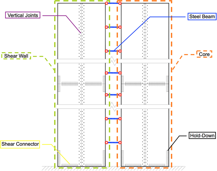
Figure 1. Schematic diagram of lateral load-resisting system.
Since the length of shear wall or/and core is larger than the commercially available mass timber panel width [2.44 m for structural composite lumber (SCL) and 3.00 m for CLT], vertical joints (Figure 1) are needed to connect adjacent panels. To resist the shear force between panels or between panel and the podium, as well as the overturning uplift force, shear connectors and hold-downs are required, as shown in Figure 1. Following capacity-based design method, the mechanical connections of this system were designed as the weakest link and source of ductility of the whole structural system. Connection types and their locations and failure sequence affect the structural performance of the buildings under seismic and wind action. In an attempt to achieve a timber LLRS for high-rise building with sufficient stiffness, strength, and ductility, dowel-type connections and HSK (wood–steel composite) system are used in the vertical joints of the shear wall and core, respectively. The HSK connection was first proposed by Bathon et al. (2006). It consists of glued-in steel plate that has circular holes in it. The steel plate is slotted into the timber member, and the slot is then filled with an epoxy resin. When the circular holes are filled with resin, it creates glue dowel, and the resistance of the connection is proportional to the number of these glued dowels in the connection. This type of glued-in plate connection is one of the strongest timber connections that are available to designers. The HSK system is also used as the shear connector and hold-down connections. The vertical joints of shear wall (dowel-type connections) and the core (HSK system) are assumed to yield sequentially, and the ultimate limit state of the building is defined as the failure of the shear connectors and hold-downs.
Hypothetical Design—CHECKER
Design Information
In the NEWBuildS tall wood building design project, it was assumed that the 20-storey hypothetical building, CHECKER, is located in North Vancouver, BC, Canada, a location that has high seismic, wind, and rain loads. The total building height is 60 m (3 m per storey), and the standard plane dimensions are 27 m × 27 m with a 9 m frame grid. The importance category of “Normal” and a site class of “D” were used for the seismic design. Various parameters linked to the design of the building are listed in Table 1 and were based on the 2010 National Building Code of Canada (NBCC) [National Research Council (NRC), 2010] for the North Vancouver location.
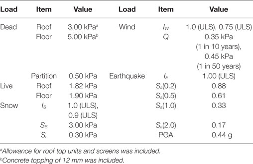
Table 1. Structural design data for North Vancouver.
Structural Design
The proposed LLRS was implemented in the design of the hypothetical 20-storey building, known as CHECKER. According to the study by Chen and Ni (2017), hybrid podium structures with a timber structure above the podium can be designed using a two-step analysis method as long as the first podium floor with a specific weight is stiff enough compared to the bottom timber floor. It indicates that the upper timber structure will behave in a similar way as if it is built on the ground. In this study, CHECKER consists of a 19-storey timber upper structure on top of a stiff concrete podium. Consequently, the structural design and analysis of this building due to wind and seismic loads focuses on the wood portion of the structure only (Chen et al., 2015). Due to symmetry of the building, only the LLRS in the east–west direction is presented.
Design provisions for novel structural system and the innovative connections are unavailable in NBCC [National Research Council (NRC), 2010] and the Canadian Standard for Engineering Design in Wood, CSAO86 [Canadian Standards Association (CSA), 2014]. Therefore, principles of mechanics and numerical simulation were used to design and estimate the structural responses of the assemblies, connections, and the whole building.
At the outset, the structural assemblies and connections were sized based on 1.6 times design wind load, since high-rise building design is usually governed by serviceability limit states of wind action and the design strengths for structural components or connections are approximately equal to their average ultimate load-carrying capacity divided by a load factor of 1.6 [Canadian Wood Council (CWC), 2010]. The analysis and design procedure is summarized below.
• Step 1—Equivalent static force procedure (ESFP) and response spectrum analysis (RSA) were performed to determine the seismic load applied on the structure based on the natural periods calculated from modal analysis. If necessary, revise assembly sizes and connection details.
• Step 2—Wind-induced response was investigated by conducting static and dynamic wind analysis. If necessary, revise assembly sizes and connection details and return to step 1.
• Step 3—Non-linear static pushover analysis was performed to determine the stiffness, strength and ductility of the structure. If necessary, revise assembly sizes and connection details and return to step 1.
• Step 4—Non-linear dynamic analysis was conducted to study the seismic responses of the building under selected earthquake excitations to confirm the seismic performance.
Static, dynamic, and experimental procedures are the three methods of determining design wind load on buildings in NBCC. What method to use is dependent on height/width ratio, height, and the lowest natural frequency of the building. Usually, the static procedure is used for buildings with fundamental natural frequency greater than 1 Hz. For cases with fundamental natural frequency between 0.25 and 1.00 Hz, the dynamic procedure shall be used. The experimental procedure is used for buildings with fundamental natural frequency less than 0.25 Hz [National Research Council (NRC), 2010]. The fundamental natural frequency of the building, fn, can be calculated using Eq. 1 according to Rayleigh’s method.
where n is the storey number; Fi is the associated wind force of storey i, which was computed using the static procedure, N; xi is the horizontal deflection of storey i caused by Fi and computed using FE analysis under static wind load, m; Mi is the associated mass of storey i, N [National Research Council (NRC), 2010]. The fundamental natural frequency of the building, 0.53 Hz, was calculated based on the deformation under static wind load. Since it is in the range of 0.25–1 Hz, the dynamic procedure was used to analyze the structural response of the building to wind action. Both the static and dynamic procedures are discussed in the wind-induced response section below. The results show that the across-wind acceleration is 0.009 g and along-wind acceleration is 0.011 g, which are less than the acceleration limit of 0.015 g for residential occupancy according to the NBCC.
The seismic load applied on the CHECKER building was estimated by using ESFP in the preliminary design. The fundamental natural period, Ta, which was estimated using Eq. 2 according to NBCC [National Research Council (NRC), 2010], is 1.04 s.
where hn is the building height. Using frequency analysis discussed below, the period of the building model was 1.97 s. It is almost twice that estimated by Eq. 2, which also usually happens to mid-rise light wood frame structures and fulfills the requirement of Sentence 4.1.8.11. 3).d).iii) in NBCC. This is because Eq. 2 was derived from measurements on concrete structures rather than timber structures, which are lighter and generally more flexible. To account for potential energy-absorbing capacity and the dependable portion of reserve strength in a structure, the concept of seismic force modification factors RoRd was adopted in NBCC. As mass timber panel system is novel, specification on the values of RoRd specifically for this type of structural system is unavailable in NBCC. An Ro of 1.5 and an Rd of 2.0 for CLT panel system with simple and standard connections are recommended by the CLT Handbook (Gagnon and Pirvu, 2011). Green and Karsh (2012) have suggested a higher Rd value of 3.5, but that suggestion was not based on any specific test evidence. The results of pushover analysis discussed below show that the ductility ratio of this LLRS was 2.55, which justifies the use of RoRd = 3.0 (1.5 × 2.0) in seismic design for the CHECKER building. A specified design base shear of about 4,900 kN was obtained using ESFP based on a period of 1.97 s and RoRd of 3.0.
The concept of capacity-based design was adopted in this project for seismic design. The mass timber panels were designed with sufficient strength so that yield or failure would occur in the connections which in turn were designed to fail in a specific sequence. Dowel-type connections with low strength and high deformability and HSK connection system with high stiffness and strength were assigned to the vertical joints of shear walls and core subsystem. HSK connection system with superior stiffness, strength, and ductility was used in the shear connectors and hold-downs at the base of the LLRS. Thus, the vertical joints of shear wall subsystem would yield first and generate most of the plastic deformation before the vertical joints of the core subsystem yield, while the shear connectors and hold-downs provide the major stiffness and strength to the whole system and fail after yielding of the vertical joints with plastic deformation.
Design Results
Based on meeting the requirements for structural loads (gravity, wind, and seismic) and fire performance of the structural members, the structural member details of a typical floor of the CHECKER building is shown in Figure 2. Grade 2.1E “TimberStrand® LSL” [Canadian Construction Materials Centre (CCMC), 1994] with dimensions of 19 m (length) × 2.44 m (width) × 89 mm (thickness) was used to build the shear wall and core subsystem. Three layers of LSL panels are combined together to build the shear wall and the core to achieve a total wall thickness of 267 mm. Steel beam S5 × 10 of Grade 50 with specified yield strength of 345 MPa (CSA, 2009) was used to connect the shear wall and core subsystem (Figure 3). Dowel-type connection of LSL using 19 mm (3/4″) dowel with a slenderness ratio of four times fastener diameter (Moses, 2000) was used as the vertical joints of shear wall, while the HSK system was used as vertical joints of core, shear connectors, and hold-downs for the whole system. For the dowel-type connection, the stiffness and strength of each dowel are 25.5 kN/mm and 32.5 kN, respectively. The HSK system is a patented product of TiComTec GmbH. In this study, the stiffness and strength of each glued dowel in the HSK system parallel to the grain are 7.4 kN/mm and 0.8 kN; while those in the perpendicular direction are 2.5 kN/mm and 0.8 kN, respectively (Bathon, 2014). The design capacities of the connections were assumed to be the measured strengths divided by 1.6. The column number and row spacing of the dowel connection, and the column number, layer number, and row spacing of glued dowel of the HSK system were determined based on the forces resisted by the corresponding connections. More details were provided by Chen et al. (2015).
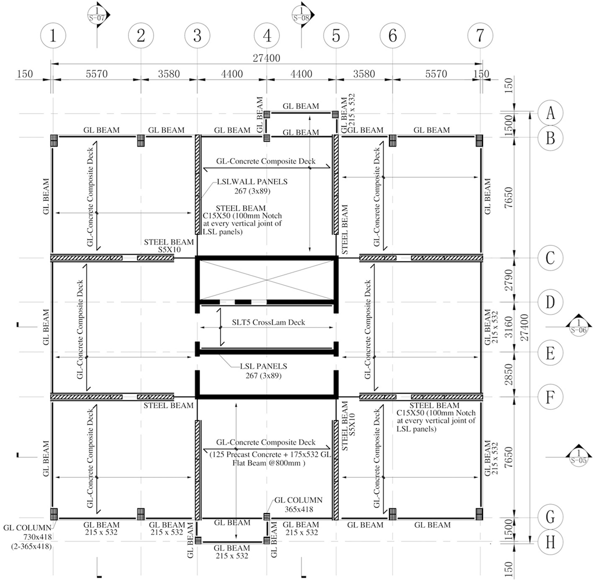
Figure 2. Typical structural member details of the CHECKER building.
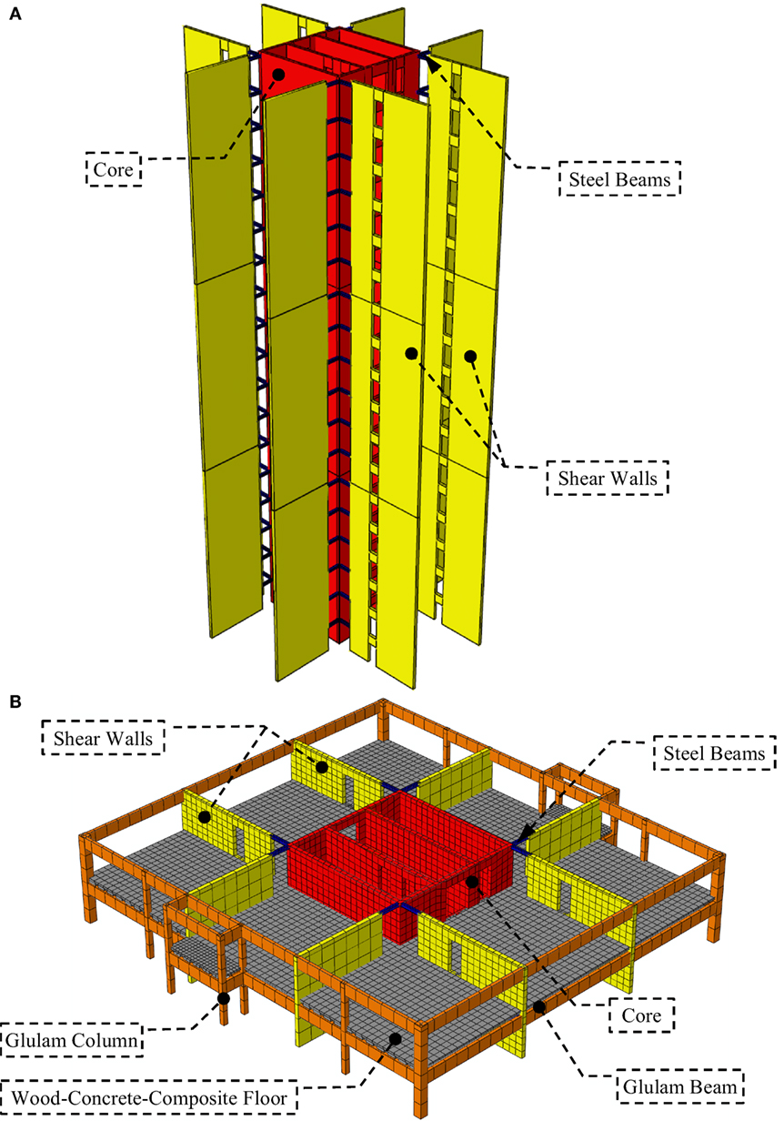
Figure 3. Lateral load-resisting system (A) and a typical storey (B) of tall wood building.
Model Development
A two-dimensional FE model of the CHECKER building (Figure 4), was developed using the general-purpose FE program, ABAQUS (Hibbitt et al., 2011). The lateral load resisting effect of the glulam frames and the constraint of floors between the core and shear walls were ignored. Only the LLRS in the east–west direction was analyzed, due to structural symmetry. The shear walls at axis C and half of the core, which resisting half of the floor areas, were modeled. An I-shape section was assumed for the analysis of the shear core, where an equivalent length of the shear core in the other direction was utilized as the thickness of the elements at the two ends of the core, to account for the core effect. The doorway openings were assumed as punched-out from the mass timber panels. The shear walls and shear core were meshed using a 4-node bilinear plane stress element (CPS4R) with reduced integration and hourglass control. The steel beams were modeled using a 2-node linear Timoshenko (shear flexible) beam element (B21). Point mass element (MASS) was used to assign the corresponding mass to each storey at the floor or roof level (Figure 4). The constitutive model of LSL was assumed to be orthotropic elasticity, while steel was regarded as an isotropic, idealized elastoplastic material. For LSL, the modulus of elasticity in the longitudinal and cross-sectional direction and the shear modulus were taken as 14,480, 810, and 905 MPa, respectively, and the Poisson ratio was taken as 0.741; with respect to steel, the modulus of elasticity and the Poisson ratio were taken as 206,000 MPa and 0.3, respectively.
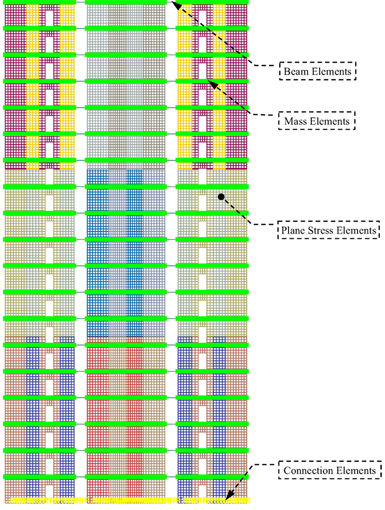
Figure 4. Finite element model (2D) of CHECKER building.
Connections play a significant role in the structural performance of the mass timber panel system, therefore the constitutive relationship between the force and deformation of the connection is the most important part of development of the FE model. As shown in Figure 4, all the LSL panels in different colors are connected together by vertical joints in the height direction. The panels are attached to the below panels or the concrete podium using shear connectors and hold-downs. A 2D, 2-node connector element (CONN2D2) was used to simulate the vertical joints, shear connectors, and hold-downs. For the purpose of reducing computation time, every connector element was used to simulate a cluster of connections in a range of 305 mm that was the dimension of an element of LSL panels. As the behavior of the connections between panels and between panel and the concrete podium was simulated by the connection models above, the interaction relationship between connecting components was simplified into frictionless in tangential direction and hard contact in normal direction. The hard contact relationship minimizes the penetration of the slave surface into the master surface at the constraint locations and does not allow the transfer of tensile stress across the interface.
Idealized models were used to model the reversed cyclic load–slip responses of HSK system and LSL dowel connection, since the load–displacement curves of these connections were unavailable. The behavior of the vertical joints and the shear connectors under shear was assumed to be idealized elastoplastic with isotropic hardening and damage behavior. A connection would be deleted from the mesh once it was damaged completely, using the element deletion technique. The hold-down connection was assumed to behave similar to the shear connectors and vertical joints under tension, but resist compression without deformation, since most of the compression deformation happens by bearing in LSL and very small deformation occurs in HSK system. Table 2 summarizes the parameters of these connection models. Hinge joints were used to connect steel beams and LSL panels.
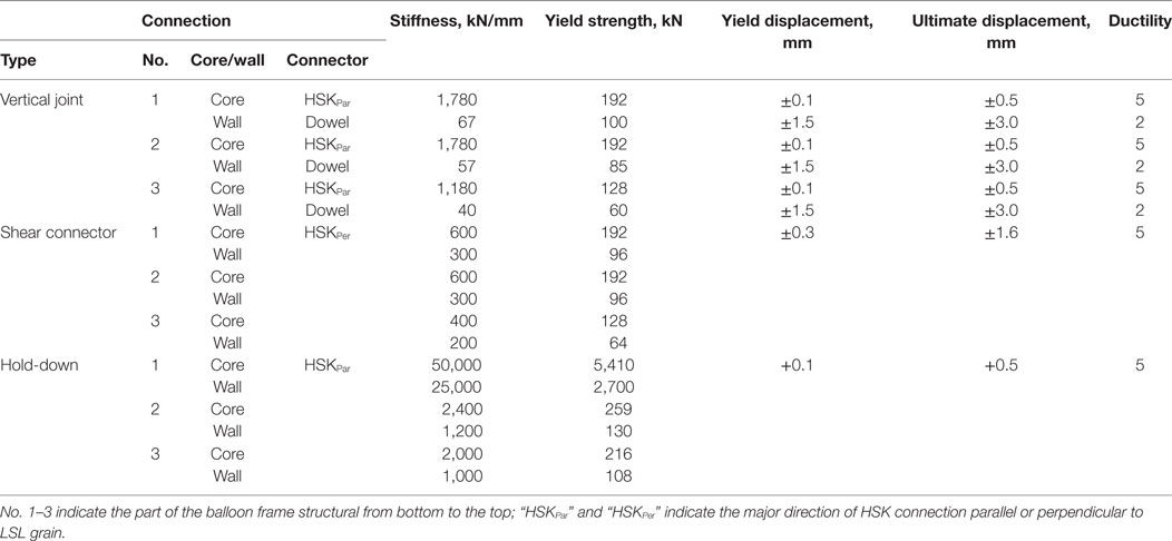
Table 2. Connection model parameters.
The FE model was meshed with a total of about 30,000 elements, including the shell, beam, connector, and mass elements. In summary, even though this FE model is a 2D model, non-linearity of material and boundary, in terms of plastic properties, damage behavior and element deletion, as well as the non-linear analysis method as indicated below are accounted for in the analysis, it is still a huge and complex numerical analysis exercise.
Wind-Induced Response
Static Wind Effect
Finite element analysis was performed to calculate the lateral deformation of the tall wood building under static wind load plus gravity load. As given in NBCC, the specified external pressure or suction due to wind on a building was calculated using Eq. 3.
where p is the specified external pressure acting statically and in a direction normal to the surface, either as a pressure directed toward the surface or as a suction directed away from the surface; IW is the importance factor for wind load (Table 1); q is the reference velocity pressure, as provided in Table 1; Ce is the exposure factor, 0.7(h/12)0.3 but not less than 0.7 since the location is classed as rough terrain; Cg is the gust effect factor, 2.0; and Cp is the external pressure coefficient, averaged over the area of the surface considered, 0.8 and −0.5 for windward and leeward sides, respectively [National Research Council (NRC), 2010]. Only one partial loading case where full wind pressure [National Research Council (NRC), 2010] was applied in east–west direction was considered. The calculated wind load, Pi, was applied at the floor or roof level, as illustrated in Figure 5.
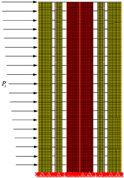
Figure 5. Wind load applied on the finite element model.
Figure 6 shows the deformation and inter-storey drift of the FE model under the design static wind load. The roof drift was 31.2 mm (≈hn/1,800), and the inter-storey drift of each storey was less than hi/500 (=6 mm) specified in NBCC. The fundamental natural frequency of the building, 0.53 Hz, was calculated using Eq. 1 based on the deformation under static wind load. Dynamic procedure was performed below because the frequency was in the range of 0.25–1 Hz [National Research Council (NRC), 2010].
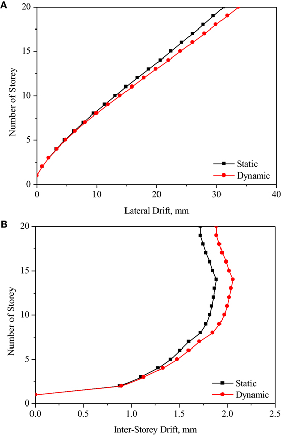
Figure 6. Storey drifts (A) and inter-storey drifts (B) of CHECKER building under static wind effect.
Dynamic Wind Effect
A numerical simulation of the FE model under dynamic wind load plus gravity load was also performed (Chen et al., 2015). The equivalent dynamic wind load was also estimated by Eq. 3. The exposure factor, Ce, and external gust effect factor, Cg, are different from the factors used in the static procedure, but the pressure coefficient, Cp, is the same. Cp = 0.8 and −0.5 for windward and leeward sides, respectively [National Research Council (NRC), 2010].
In the dynamic procedure, the exposure factor, Ce, is based on the profile of mean wind speed, which varies considerably with the general roughness of the terrain over which the wind has been blowing before it reaches the building [National Research Council (NRC), 2010]. Since this building is located at exposure A (rough exposure) terrain, Ce can be calculated by Eq. 4 [National Research Council (NRC), 2010].
The gust effect factor, Cg, which is defined as the ratio of the maximum effect of the loading to the mean effect of the loading, and according to NBCC, the gust effect factor of the CHECKER building under dynamic wind load was 2.36. The storey drift and inter-storey drift of the FE model under the design dynamic wind effect are shown in Figure 6. The results show that the response of the building under dynamic wind load, in terms of storey drift and inter-storey drift, was slightly larger than that induced by the static wind load. The roof drift is 33.7 mm (≈hn/1,700), and the inter-storey drift of each storey is less than the hi/500 limit (=6 mm) specified in NBCC.
In the dynamic procedure, not only the wind-induced lateral deformation but also the vibration and vortex-shedding effect are checked. While the maximum lateral wind loading and deflection are generally in the direction parallel to the wind (i.e., the along-wind direction), the maximum acceleration of a building leading to possible human perception of motion or even discomfort may occur in the direction perpendicular to the wind (i.e., the across-wind direction). Across-wind accelerations are likely to exceed along-wind accelerations if the building is slender about both axes, that is if is less than one-third, where w and d are the across-wind effective width and along-wind effective depth, respectively, and H is the height of the building. The across- and along-wind accelerations, aW and aD (m/s2), are calculated from Eqs 5 and 6.
where (in N/m3); ρB is average density of the building (in kg/m3); βW and βD are fraction of critical damping in across- and along-wind directions, respectively, and are taken as 0.015 according to NBCC; fnW and fnD are fundamental natural frequencies in across-wind and along-wind directions, respectively (in Hz); Δ is maximum wind-induced lateral deflection at the top of the building in along-wind direction (in m), which was obtained by conducting FE analysis on the CHECKER building under dynamic wind load; and g is acceleration due to gravity = 9.81 m/s2 [National Research Council (NRC), 2010]. Using Eqs 5 and 6, the across- and along-wind accelerations were calculated to be 0.009 and 0.011 g, respectively. They are less than the acceleration limit of 0.015 g for residential occupancy [National Research Council (NRC), 2010].
Seismic Performance
Linear Dynamic Response
Response spectrum analysis is typically utilized to evaluate the seismic performance of buildings under design response spectrum acceleration. In an attempt to obtain accurate results from RSA, a sufficient number of vibration modes must be extracted to model the dynamic response of the system. A criterion to determine the required number of modes involved is that at least 90% of the mass must participate in the modal analysis in the direction of interest [National Research Council (NRC), 2010]. For the CHECKER building, it was found via FE analysis that this criterion was met when 20 vibration modes were involved in the RSA.
A base shear of 4,500 kN was obtained from the RSA. Note that this is similar to the design seismic force derived by ESFP in the preliminary design. Figure 7A shows the lateral deflection of each storey obtained by RSA. According to NBCC, the calculated lateral deflection using RSA should be multiplied by RdRo/IE to account for plasticity of the system [National Research Council (NRC), 2010]. The inter-storey drift shown in Figure 7B is less than the 2.5% hs limit (=75 mm) specified in NBCC.
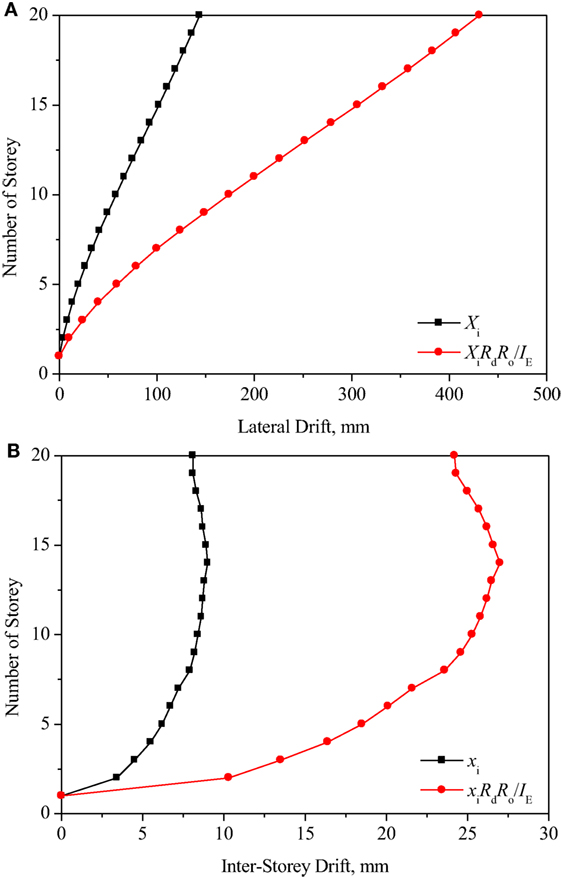
Figure 7. Storey drift (A) and inter-storey drift (B) of CHECKER building under earthquake using response spectrum analysis.
Non-Linear Static Response
Non-linear static pushover analysis was performed on the CHECKER building model using an inverse triangular loading pattern to investigate the failure mechanism of the LLRS. The total force resisted at the bottom of the building is plotted against a reference displacement at the top of the model to define a capacity curve, as shown in Figure 8.
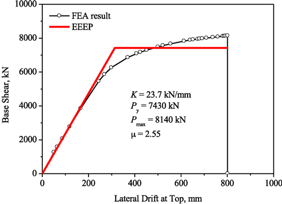
Figure 8. Plot of base shear vs top storey lateral drift of CHECK building based on FE analysis, and idealized bilinear response using the EEEP method.
As shown in Figure 8, the load increases linearly with displacement in the initial elastic stage (0–5,500 kN). Then, the relationship between load and displacement becomes non-linear, as the vertical joints of shear wall and core yield sequentially (Figures 9A,B). Once the shear connectors and hold-downs yield and then fail completely (Figures 9C,D), the building loses its lateral resistance, as shown in Figure 9E. Since idealized constitutive models with abrupt unloading mechanism were adopted to model the connections, the load–displacement curve dropped sharply once the modeled connection reached its capacity. This analysis has shown that the structure would fail according to the intended sequence, thereby verifying the adopted capacity-based design approach.
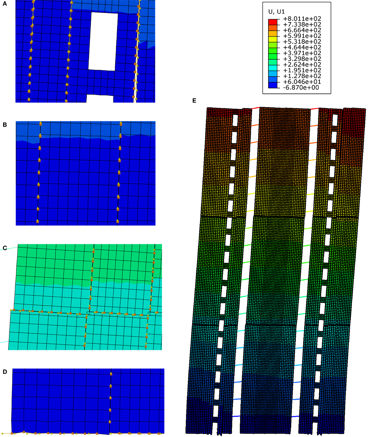
Figure 9. Deformation of connections and building finite element (FE) model (scale factor is 5): (A) vertical joints of shear wall, (B) vertical joints of core, (C) connections between core panels, (D) connections of core panels, and (E) deformation of FE model.
The load–displacement curve of the tall wood building model was analyzed using equivalent energy elastic–perfectly-plastic (EEEP) method in accordance with ASTM Standard E2126 (ASTM, 2011). The EEEP procedure basically ensures that the area under the measured load–slip curve (energy dissipation) is the same as the equivalent EEEP bilinear model shown in red in Figure 8. Using this procedure, the initial stiffness, yield load, and maximum load reached are 23.7 kN/mm, 7,430 kN, and 8,140 kN, respectively. The maximum load is about 1.6 times the design seismic force derived by ESFP. The ductility ratio of this building model is 2.55. Using Eq. 7 for medium and long period buildings (Newmark and Hall, 1982; Chen et al., 2014), a corresponding Rd factor of 2.55 was obtained. A conservative value of 2.0 was used for the seismic design, as was discussed above.
Non-Linear Dynamic Response
The non-linear dynamic behavior of the CHECKER building model under design hazard level was analyzed with the explicit dynamic analysis method using the central-difference operator (Hibbitt et al., 2011). Ten “Far-Field” earthquake records (NGA #: 169, 721, 752, 829, 900, 1111, 1158, 1244, 1602, and 1787) in the fault normal direction [Applied Technology Council (ATC), 2009] (Table 3 were scaled at the corresponding fundamental period of the building model (1.97 s) to match the spectral acceleration, Sa, of the North Vancouver design spectrum, as shown in Figure 10.
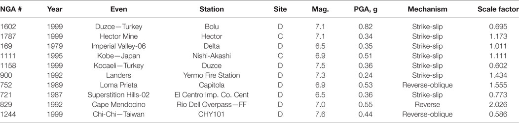
Table 3. Summary of selected horizontal PEER ground motion records.
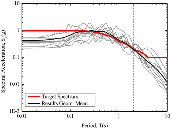
Figure 10. Earthquake records scaled to target spectrum (5% damping) at 1.97 s.
A scaled input acceleration of an earthquake (NGA #: 1602) with a duration of 15 s, and the structural responses, in terms of base shear, lateral drift at top and inter-storey drift ratio of the building are shown in Figure 11. Connections play a significant role in the structural performance of the mass timber panel system. Due to lack of the load–displacement curves of the connections under cyclic loading, idealized elastoplastic models with isotropic hardening and damage behavior were used to model the reversed cyclic load–slip responses of HSK system and LSL dowel connection. Similar idealized hysteresis loops were derived from the lateral resisting system.
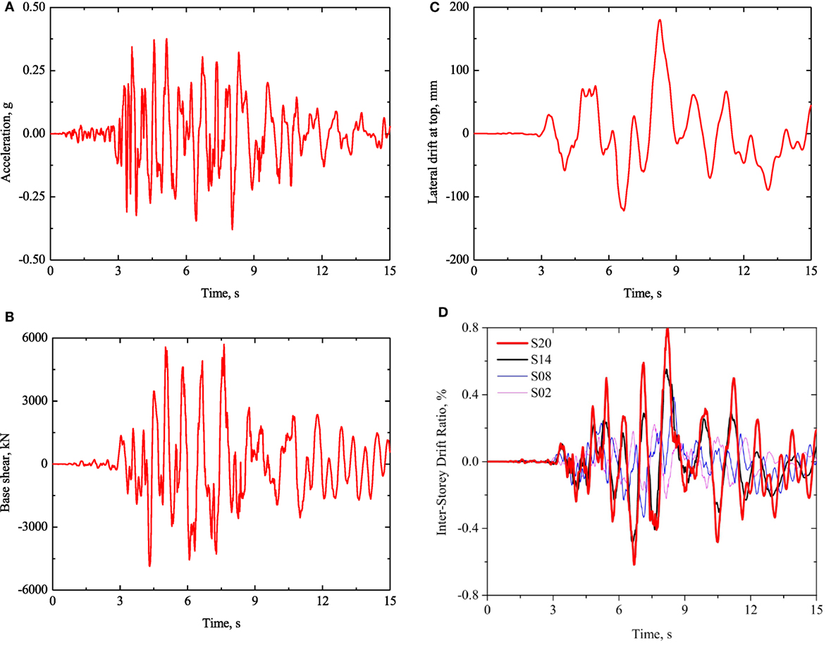
Figure 11. Seismic response of the finite element model: (A) scaled earthquake acceleration (NGA #: 1602), (B) base shear, (C) lateral drift at top, and (D) inter-storey drift ratios: S02, S08, S14, and S20 represent the 2nd, 8th, 14th, and 20th storey.
Figure 12 shows the statistics for the base shear and inter-storey drift ratio of the tall wood building under the 10 earthquake excitations, along with the design base shear of 4,893 kN estimated by ESFP, the yield load of 7,430 kN calculated using the EEEP procedure of ASTM 2126 (ASTM, 2011), and the maximum capacity of 8,140 kN of the building calculated from pushover analysis. Figure 12A illustrates that most (nine) of the base shears of the building are higher than the design value of 4,893 kN. However, all the base shear values are less than the yield load of 7,430 kN and the maximum capacity of 8,140 kN. In addition, as shown in Figure 12B, all the inter-storey drift ratios are less than the design criterion of 2.5% specified in NBCC. It should be noted that under all earthquakes only the vertical joints between the shear walls of the tall wood building showed yielding behavior.
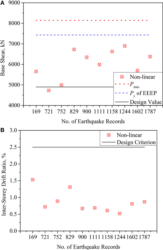
Figure 12. Summary of responses of the CHECKER building to 10 earthquake excitations: (A) base shear and (B) inter-storey drift ratio.
Conclusion
In this study, an LLRS using mass timber panel on a stiff podium was developed and implemented in the design of a hypothetical 20-storey building. Based on the structural design and the FE analysis of this building, the following conclusions can be derived:
• The LLRS consisting of eight shear walls and a shear core made of SCL and linked by steel beams with hinge joints was viable for high-rise buildings.
• The wind-induced and seismic responses of tall wood buildings under static and dynamic wind and seismic effects, respectively, met the design criteria of NBCC.
The connection systems, consisting of a combination of steel dowels and HSK system (glued dowel in steel plate), designed in accordance with capacity-based design method play a key role in developing sufficient stiffness, strength, and ductility for the LLRS to resist wind and seismic loads. This study has shown that the connection systems have a strong influence on the structural performance of the building. A capacity-based design approach should be adopted for tall wood buildings to ensure that first yield and failure do not occur at the base shear connections and hold-downs. To that end, connection system with high stiffness and high ductility or deformation ability and low strength should be used in vertical joints; while strong and stiff connection system should be used as shear connectors and hold-downs.
This study provides a valuable insight into the structural performance of LLRS using mass timber panels as a viable option for high-rise buildings. The analysis and design approach can be extended to other tall buildings containing engineered mass timber panels.
Author Contributions
YH-C and ZC—equal contribution to the work.
Conflict of Interest Statement
The authors declare that the research was conducted in the absence of any commercial or financial relationships that could be construed as a potential conflict of interest.
Acknowledgments
The authors greatly acknowledge the expert advice provided by Mr. Eric Karsh and Dr. Mahmoud Rezai of Equilibrium Consulting Inc., Vancouver, BC, Canada. Mechanical specifications and test data on the HSK connection system were provided by Prof. Leander Bathon, University of Wiesbaden, Germany. Thanks are also extended to Mr. Mark McCormick, P.Eng. from exp Services Inc., Fredericton, NB, Canada, and Dr. Marjan Popovski, FPInnovations, Vancouver, BC, Canada for providing technical advice. Some of the text and figures in this paper have been published in a NEWBuildS report cited in the Reference section and a 2015 ASCE Structures Congress Conference Proceedings paper by the authors. They are reproduced here with permission from ASCE.
Funding
This project was conducted with financial support of Natural Sciences and Engineering Research Council (NSERC) of Canada through its Strategic Research Network Program and BC Forestry Innovation Investment (FII) through its Wood First program.
References
Applied Technology Council (ATC). (2009). Quantification of Building Seismic Performance Factors. ATC-63/FEMA P-695 Project Rep., Redwood City.
ASTM. (2011). Standard Test Methods for Cyclic (Reversed) Load Test for Shear Resistance of Framed Walls for Buildings. ASTM E2126, West Conshohocken.
Bathon, L., Bletz, O., and Schmidt, J. (2006). Untersuchungsbericht zum Holz StahlKlebeverbundsystem mit eingeklebten Lochblechen (HSK-System). Fachhochschule Wiesbaden, Holzbaulabor.
Canadian Construction Materials Centre (CCMC). (1994). TimberStrand® LSL. Evaluation Report CCMC 12627-R. Boise: Weyerhaeuser.
Canadian Standards Association (CSA). (2014). Engineering Design in Wood. CSA O86-14. Toronto: Canadian Standards Association.
Chen, Z., Chui, Y. H., Ni, C., and Xu, J. (2014). Seismic response of midrise light wood-frame buildings with portal frames. J. Struct. Eng. doi:10.1061/(ASCE)ST.1943-541X.0000882
Chen, Z., Chui, Y. H., and Popovski, M. (2015). “Chapter 2 – Development of Lateral Load Resisting System.” In Application of Analysis Tools from NEWBuildS Research Network in Design of a High-Rise Wood Building. Report of the NSERC Strategic Research Network on Innovative Wood Products and Building Systems. Fredericton, NB: University of New Brunswick.
Chen, Z., and Ni, C. (2017). Seismic Response of Mid-Rise Wood-Frame Buildings on Podium. FPInnovations Report No. 301011233 Report, Vancouver, Canada.
Gagnon, S., and Pirvu, C. (2011). CLT Handbook Canadian Edition. Quebec: FPInnovations Special Publication SP-528E.
Green, M. C., and Karsh, J. E. (2012). The Case for Tall Wood Buildings. Forestry Innovation Investment (FII) Report, Vancouver.
Hibbitt, D., Karlsson, B., and Sorensen, P. (2011). ABAQUS Analysis User’s Manual (Version 6.11). Pawtuck: Dassault Systemes Simulia Corp.
Karacabeyli, E., and Lum, C. (2014). Technical Guide for the Design and Construction of Tall Wood Buildings in Canada. FPInnovations Report, Quebec.
Moses, D. M. (2000). Constitutive and Analytical Models for Structural Composite Lumber with Applications to Bolted Connections. Ph.D. dissertation, Department of civil Engineering, University of British Columbia, Vancouver.
National Research Council (NRC). (2010). National Building Code of Canada. Ottawa: Canadian Commission on Building and Fire Codes, NRC.
Keywords: high-rise building, wood structure, lateral load-resisting system, mass timber, wind-induced response, seismic response
Citation: Chen Z and Chui Y-H (2017) Lateral Load-Resisting System Using Mass Timber Panel for High-Rise Buildings. Front. Built Environ. 3:40. doi: 10.3389/fbuil.2017.00040
Received: 30 March 2017; Accepted: 28 June 2017;
Published: 14 July 2017
Edited by:
Koji Yamada, Toyota National College of Technology, JapanReviewed by:
Takafumi Nakagawa, National Institute for Land and Infrastructure Management, JapanShinta Yoshitomi, Ritsumeikan University, Japan
Izuru Takewaki, Kyoto University, Japan
Copyright: © 2017 Chen and Chui. This is an open-access article distributed under the terms of the Creative Commons Attribution License (CC BY). The use, distribution or reproduction in other forums is permitted, provided the original author(s) or licensor are credited and that the original publication in this journal is cited, in accordance with accepted academic practice. No use, distribution or reproduction is permitted which does not comply with these terms.
*Correspondence: Ying-Hei Chui, yhc@ualberta.ca