Seismic-Proof Buildings in Developing Countries
 Vittoria Laghi
 Michele Palermo
 Tomaso Trombetti
 Martijn Schildkamp
- 1Department of Civil and Environmental Engineering, University of Bologna, Bologna, Italy
- 2Smart Shelter Research, Amsterdam, Netherlands
The use of “ductile seismic frames,” whose proper seismic behavior largely depends upon construction details and specific design rules, may do not always lead to effective seismic resistant structures, as dramatically denounced by the famous Chinese artist Ai Weiwei in his artwork Straight. The artwork (96 t of undulating metal bars that were salvaged from schools destroyed by the 2008 Sichuan, China earthquake, where over 5,000 students were killed) is a clear denounce against the corruption yielding to shoddy construction methods. The issue of safe constructions against natural hazards appears even more important in developing countries where, in most cases, building structures are realized by non-expert workers, or even by simple “people from the street,” who does not have any technical knowledge on construction techniques and seismic engineering. In this paper, a brief history from the first frame structures to the more efficient wall-based structures is provided within Earthquake Engineering perspectives. The superior structural properties of box-type wall structures with respect to conventional frame structures envisage a change of paradigm from actual “ductility-based” Earthquake Engineering (centered on frame structures) toward 100% safe buildings through a “strength-based” design exploiting the use of box-type wall-based structures.
Introduction
According to the World Bank—Global Facility for Disaster Reduction and Recovery, in the last decades, low- and middle-income countries have experienced 53% of all disasters globally but have accounted for 93% of disaster-related fatalities. Often, disasters such as earthquakes, tsunamis, cyclones, and flooding disproportionately impact poor populations living in unsafe buildings and areas more exposed to these natural hazards, which are likely to increase in frequency and intensity in the future (Moullier and Krimgold, 2015). By 2050, it is expected that one billion new dwelling units will be required to house the world’s growing population, thus the issue of making safe and regulated building practices is one of the main challenges for the next future. Indeed, while in high-income countries building codes and regulatory frameworks have been incrementally improved over the course of the past century (in response to a combination of specific local aspects such as hazard impacts, structural failures, and public health disasters, thus increasing people’s safety and resilience), in low- and middle-income countries, the regulatory systems have not followed an incremental development, but more often regulations borrowed from other countries were adopted in toto.
In this respect, the World Bank program does not simply look to transfer mature regulatory systems to developing countries but clearly recognizes the need of specific adaptation to local culture, economic, social, and institutional factors affecting compliance. For this reason, a localized and calibrated approach, along with awareness of the wider socioeconomic and development context, has to be followed. Smart Shelter Research1 is driving toward this direction through a number of activities aimed at establishing reliable, tested and validated knowledge regarding semi-engineered construction techniques based on the use of local materials and manpower, by making them understandable and applicable to all user groups working in developing countries and hazardous contexts. Between 2007 and 2012, Smart Shelter not only built several schools and houses in India, Nepal, and Indonesia, making use of local laborers but also continuously instructed local communities in using good construction practices. For instance, to leave a tangible and permanent sign in the memory of local habitants, the exterior walls of the schools present explanations and illustrations of the adopted construction techniques as shown in Figure 1. The lesson learned during years of experience by Smart Shelter Research and other similar institutions revealed that modern reinforced concrete (RC) framed constructions (extensively used in Europe and USA), whose safety is grounded upon the adoption of peculiar detailing able to guarantee a ductile behavior, in most cases are not properly built in developing countries. Dramatic consequences in terms of human safety were caused by the collapse of numerous RC school buildings in China during the earthquakes that stroke the Sichuan region in 2008 (more than 10,000 students died for a total 69,000 lives lost) (Yin et al., 2009). The tragedy is symbolically represented by the Chinese artist Ai Weiwei in his work called Straight, shown in Figure 1. The artwork (an assemblage of 96 t of straighten steel rebar from the sites of the collapsed schools) wants to denounce the substandard building methods applied to regional government building projects in China, which contributed to cause those fatalities.
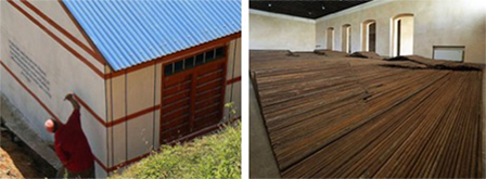
Figure 1. On the left: earthquake-resistant school built by the Smart Shelter Foundation in Nepal (courtesy of Smart Shelter Foundation); on the right: artwork “Straight” by the Chinese artist Ai Weiwei, Royal Academy (London, UK).
Frame Structures: The Need of “Ductility-Based” Seismic Design
Brief History of Frame Structures
Masonry-wall constructions have been used for at least 10,000 years to build a variety of constructions such as dwellings, public buildings, and monuments. Up to the mid nineteenth century, masonry constructions were the most used construction system all over the world, until the introduction, with the Industrial Revolution, of new construction materials such as steel and concrete, which allowed the development of a new construction system: the frame.
The first frame building structures were realized during the reconstruction of the city of Chicago after the “Great Fire” of 1871. The new tall steel buildings made the city be known as the “Skyscraper City.” These first frame structures were realized using steel frames braced by diagonal elements providing the required strength and stiffness against wind loads. Figure 2 shows the “Unity” building, a steel frame built in Chicago in 1892, as well as the “Monadnock” Building, the tallest masonry building ever constructed, which was also built in Chicago.
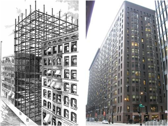
Figure 2. From the left: Unity Building, Chicago (courtesy of Chicago History Museum); Monadnock Building, Chicago (courtesy of David K. Staub).
In the last decades of the nineteenth century, the first RC frame buildings were realized in France. The pioneers of RC frames were perfectly conscious of the limited lateral strength capabilities on the new construction system, as shown by the attention they paid in the beam–column connections, which were often enlarged to increase the joint resistance against horizontal actions. Indeed, the frames were primarily conceived to withstand gravity loads and to provide more flexibility in the use of the internal spaces. Robert Maillart himself (the Swiss engineer who revolutionized the use of structural RC with such designs as the three-hinged arch and the deck-stiffened arch for bridges), carried out specific experimental tests on RC frames to assess their capabilities in carrying flexural actions induced by asymmetric gravity loads (Billington, 1991).
These first experimental tests, aimed at, somehow, assessing the lateral strength of RC frames, were carried out almost 40 years before the first studies dealing with real recorded earthquake data (1933 Long Beach Earthquake), which according to Housner (1984) determined “the most important step toward the development of Earthquake Engineering” (Bozorgnia and Bertero, 2004) clarifying that earthquakes may induce significant actions upon frame structures. Nonetheless, at that period (before modern Earthquake Engineering was established), the RC frames were already the most commonly adopted structural system (especially in Europe and USA). This is the main reason behind the so-relevant research efforts devoted to the study of the seismic behavior of RC culminating in the modern “ductility-based” vision of the Earthquake Engineering.
“Ductility-Based” Seismic Engineering: Vision 2000 and Actual Seismic Codes
During the 1971 San Fernando Earthquake, RC frame structures experienced large inelastic responses and severe damages, thus highlighting their inherent insufficient strength capabilities and the need of large ductility to ensure a good seismic behavior. The conceptual breakthrough that paved the way toward current trends in Earthquake Engineering is represented by the design approach proposed by the SEAOC Vision 2000 Committee (1995), known under the name of Performance-Based Seismic Design (PBSD), followed by actual research trends in Direct Displacement-Based Design procedures (Bertero and Bertero, 2002; Priestley et al., 2007). The new design philosophies are grounded on the full exploitation of the non-linear deformation capacities, thus requiring a complete knowledge of structural and non-structural components behaviors, identified in terms of Engineering Demand Parameters.
This framework is explicitly aimed at addressing life-safety, damageability, and functionality issues that are identified in terms of Performance Objectives, namely, a certain performance of a building (performance level) under a given hazard level (earthquake design level), as shown in Figure 3. For instance, for a building of “basic” importance (such as dwellings), the seismic design will be conducted to satisfy the following Performance Objectives: (1) for a frequent earthquake, the building has to remain fully operational (Fully Operational performance level), (2) for an occasional earthquake, the structural elements have to remain undamaged with only minor damages of the non-structural components (Operational performance level), (3) for a rare earthquake, the safety of the occupants has to be guaranteed (Life Safety performance level), and (4) for a very rare earthquake, the global stability has to be preserved (Near Collapse performance level).
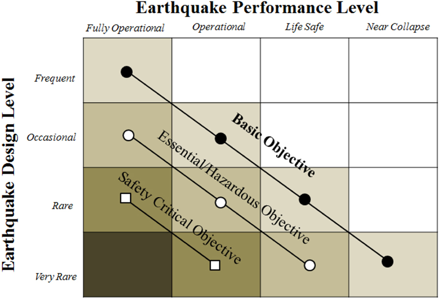
Figure 3. Performance Objectives for buildings [adapted from SEAOC Vision 2000 Committee (1995)].
Nonetheless, the exploitation of the complete inelastic capacity of a frame building requires the following: (i) in the design phase, the accomplishment of sophisticated design prescriptions included in modern seismic codes (such as appropriate behavior factor based on the expected ductility capacity, equivalent viscous damping, capacity design criteria, connections detailing, etc.) and (ii) during construction phase, the application of precise and complex procedures, requiring the presence of expert labor. As such, even though in principle these new trends in structural design would allow for a full knowledge of the structural behavior of a building during an earthquake, at the same time they introduce additional uncertainties in the design phase and a complex detailing in the construction phase, which have to be properly addressed to obtain a reliable design and the desired behavior under an earthquake. Furthermore, these issues appear even more relevant when dealing with buildings to be designed and constructed in developing countries.
Lateral Systems for Tall Buildings: The Premium for Height
Brief History of Structural Systems for Tall Buildings
In the late nineteenth century, most tall buildings employed steel rigid frames with wind bracings or rigid concrete frames. However, their significant height for the time was accomplished through the excessive use of material and overdesign (Ali and Moon, 2007). The primary structural skeleton of a tall building can be schematized as a cantilever beam, clamped at the base (e.g., the ground) which has to carry both vertical gravity loads and the lateral loads due to wind (and/or earthquake). The building must therefore have adequate shear and flexural strength to resist to the internal actions induced by lateral loads, which tend to increase as the building gets taller and taller. Master builder Fazlur Khan was the first, in the 1960s, to realize that, as the building becomes taller, there is a high “premium for height” to be paid in terms of amount of material required (Ali, 2001). To reduce such premium, more efficient lateral resisting systems are to be used (Khan and Sbarounis, 1964). Then, in 1969, he first classified structural systems for tall buildings in the form of “Height for structural systems” diagrams (Figure 4): frames appear adequate for buildings up to around 10 stories, while for higher constructions, shear walls, core supported structures, tubular structures, modular or bundled tubes are much more efficient systems (Khan, 1972, 1973). Examples of such innovative structural solutions (Figure 5) are in pioneering buildings, such as: John Hancock Building (completed in the 1969) and Sears Towers (completed in 1974) designed by Khan (1967, 1969), and the Onterie Center designed by Skidmore, Owings & Merrill (completed in 1986). More recent buildings with innovative structural solutions are the 30 St. Mary’s Axe in London designed by Foster (completed in 2004), the Agbar Tower in Barcelona designed by Jean Nouvel (completed in 2005), and the CCTV in Beijing designed by Office for Metropolitan Architecture (completed in 2008).
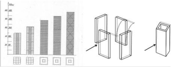
Figure 4. On the left: structural systems for tall buildings [adapted from Pozzati and Ceccoli (1980)]. On the right: wall versus tube behavior [adapted from Khan (2004)].
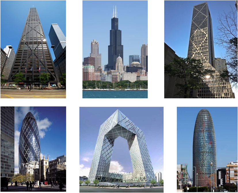
Figure 5. From the top left, clockwise: John Hancock Building (courtesy of Royce Douglas); Sears Tower (courtesy of Michiel Van Dijk); Onterie Center (courtesy of Marshall Gerometta); Agbar Tower, Barcelona (courtesy of Mary Ann Sullivan); CCTV, Beijing (courtesy of Office for Metropolitan Architecture); and 30 St. Mary’s Axe, London (courtesy of Nigel Young).
The so-called “tube,” which was identified by Khan as one of the most efficient earthquake-resistant systems, has the same working principle of the typical building type constructed in most European countries since Middle Age: low-rise masonry-wall constructions. For instance, in Italy, more than 60% of the buildings are low-rise masonry buildings constructed before 1970 (ISTAT 2001).2 Indeed, these types of structures are typically characterized by quite regular plans (often rectangular) with external perimeter walls and interior walls standing from the ground to the roof (only partially perforated due to the presence of few openings, e.g., doors and windows) connected to each other to obtain a sort of “box” behavior [see the famous schematization of Touliatos (1996) reproduced in Figure 6]. Even though the construction materials (brick and mortar) were characterized by quite poor mechanical properties (practical null tensile strength and limited compression strength), the resistance against lateral loads was merely due to a box-type structural response: in-plane response of the walls parallel to the seismic input with negligible out-of-plane solicitations thanks to proper connections between orthogonal walls along with the presence of perimeter roof beams (Casapulla and Argiento, 2016). However, this resisting mechanism (box-type behavior) is guaranteed only if proper connections between the adjacent vertical panels and between the panels and the floor slabs are present.
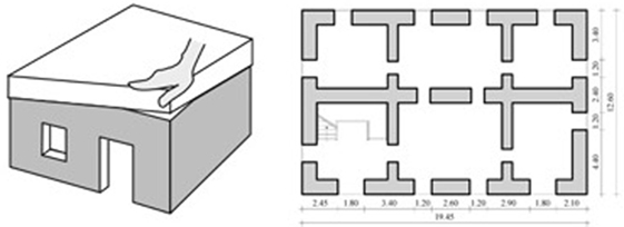
Figure 6. From the left: “Box” behavior [adapted from Touliatos (1996)]; typical plan of a masonry building (Parisi and Augenti, 2012).
In light of all of above, the coupling of a “tubular” behavior with new high-performance construction materials, such as concrete and steel, would ensure the building structure to reach optimal performances under earthquakes with superior strengths and limiting the excursion within the inelastic field.
Seismic Behavior of RC Shear Wall Structures
Since the use of shear wall buildings is not predominant in most earthquake-prone countries (USA, Europe), researchers did not pay too much attention in the study of the seismic response of RC wall structures, especially for the case of low-rise buildings, realized with squat RC walls (Hidalgo et al., 2002). Despite the low amount of research works devoted to wall structures, buildings made by shear walls showed quite superior performances during strong earthquakes, such as the ones which stroke Chile on March 3rd, 1985 (Wood, 1991) and February 27th, 2010 (Carpenter et al., 2011).
Shear walls are typically designed to exhibit a ductile behavior (Synge et al., 1980; Paulay et al., 1982) by ensuring the ultimate shear strength being higher than the shear corresponding to develop flexural yielding in the vertical boundary reinforcement of the walls. In such a case, the shear walls would develop a ductile flexural mode of failure, thus even ensuring inelastic resources in the case of severe earthquakes. Nonetheless, the lesson learned from the seismic behavior of Chilean buildings shows that detailing of RC elements to absorb and dissipate energy through the development of ductile flexural behavior is not the only way to achieve a satisfactory seismic response during severe earthquake events. When the total cross section area of walls is large enough [say 0.02–0.04 times the floor plan area in each direction, according to Lagos et al. (2012)], the ductility demand is kept at a moderate level in tall buildings and practically does not develop in low-rise buildings, which thus practically remain within the elastic field. Moreover, shear stresses are limited to values around 0.5 MPa (well below material shear strength). The achievement of such a good seismic behavior is ensured by the very large lateral strength and stiffness of RC walls, and therefore does not require the use of sophisticated design procedures and complex detailing. The simple rules ensuring the good seismic response of Chilean RC wall buildings have configured in what has been called the typical Chilean RC building (Lagos et al., 2012). Even though PBSD procedures were not included in Chilean building codes up to 2010, the experience showed that the typical Chilean building response was close to the Operational performance level under a rare earthquake and close to the Fully Operational performance level under an occasional earthquake (Lagos et al., 2012).
Seismic Behavior of Tubular RC Structures
A tube (or tubular structure) can be defined as a three-dimensional structural system that utilizes the entire perimeter to resist lateral loads. As abovementioned, Fazlur Khan, thanks to his deep knowledge in mechanics of materials and structural behavior, was the first to realize that a structure could be treated in a holistic way, that is, the building can be analyzed in three dimensions (Ali and Moon, 2007). He first introduced the concept of tubular structures in 1961, then in 1965 he designed the 43-storey DeWitt-Chestnut Apartment Building in Chicago, known as the first framed tube building. Later on, super-tall buildings, such as the 100-storey John Hancock Center (1969), the 110-storey Sears Tower (1974), the 83-storey Amoco building (1974), all in Chicago, and the 110-storey World Trade Center Towers (1973) in New York were designed exploiting the tube concept.
Tubular structures involve a range of related structural forms: framed tube, tube-in-tube, bundled tube, braced tube, and composite tube (Figure 7). The basic design philosophy in all these forms is to centrifuge as much as possible the lateral resisting elements, by locating them around the perimeter so that the building flexural rigidity is close to the one of a tubular cantilever continuous beam. The framed tube, in its basic form, consists of four orthogonal rigidly jointed frame panels, having quite closely spaced columns connected by deep spandrel beams at each floor. Typically, the exterior tube is designed to entirely carry the lateral loads. The frames parallel to the lateral load direction act as the “webs” of the tube cantilever, while those perpendicular to the lateral load direction act as the “flanges.” The vertical gravity loads are resisted partially by the exterior frames and partially by some inner structures (columns or cores). Given that the horizontal loads are resisted by the exterior tube, the tubular structure has noteworthy architectural advantages since more freedom in planning the interior spaces is permitted. Even though the principal resisting mechanism of the framed tube is the same of an equivalent unperforated tube governed by the Euler–Bernoulli beam theory (e.g., the webs carry most of the shear while the flanges carry most of the bending moment through couples of axial forces), the flexibility of the spandrel beams does not ensure the conservation of plane sections thus determining additional (or secondary) stresses concentrated in the outer columns (related to the shear lag phenomenon). To reduce the shear lag effects, additional interior tubes may be added to create so-called bundled tube structures. Under lateral loads, the presence of the in-plane rigid floors constraints the interior tubes to deflect equally the exterior tubes, thus reducing the amplitudes of the additional stresses due to the shear lag. Another structural solution leading to a similar global behavior is based on the use of coupled shear walls to form the interior web of the framed tube, while an even more efficient structural system (particularly indicated for very tall buildings) is the so-called braced tube (Figure 7). By eliminating the exterior columns and replacing them with diagonals in both directions so closely spaced to behave as bearing walls (Smith et al., 1991), the braced tube would, in principle, allow to obtain the ideal behavior of a full cantilever tube.
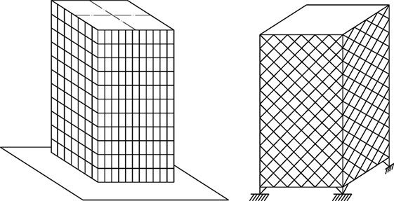
Figure 7. Structural systems for tall buildings: (from the left) framed tube [adapted from Smith et al. (1991)]; braced tube [adapted from Smith et al. (1991)].
From Nervi’s Ferrocement to Modern Insulating Concrete Forms (ICFs)
Brief History of Ferrocement
Ferrocement is a building material composed of cement, sand, water, aggregates and a metallic mesh. The ACI Committee 549 (2010) has given the following definition for Ferrocement in their report in 1988: “Ferrocement is a form of reinforced concrete using closely spaced multiple layers of mesh and/or small diameter rods completely infiltrated with, or encapsulated in, mortar.” It was invented by Joseph-Louis Lambot in the mid of nineteenth century for the construction of a boat. Lambot exhibited the vessel at the Exposition Universelle in 1855 and termed the new material with the name of “ferciment,” and in the same year patented his batteau. Later in the twentieth century, the Italian engineer Pier Luigi Nervi patented the ferrocement (1943) and used the new material, together with innovative construction techniques (known under the name of “Nervi system”) for the realization of revolutionary constructions for the time, such as various soccer stadiums. In particular, with the “Giovanni Berta” stadium in Florence, Nervi became famous even out Italy frontiers.
The main peculiarity of the ferrocement is the use of a fine and closely spaced mesh grid (bar diameter of few millimeters spaced at few centimeters) which allows to uniformly spread the steel mechanical properties (first of all, a much larger tensile strength with respect to that of concrete) within the entire structural element (Figure 8). The presence of the metallic mesh grid leads to a structural material with good behavior both in compression and tension as well as superior deformation capacities with respect to the traditional RC. Ferrocement, thanks to its enhanced mechanical properties, was also used to realize very thin shell structures such as the one covering the Nervi’s Palazzetto dello Sport in Rome (completed in 1960) (Figure 8).
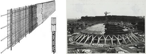
Figure 8. From the left: example of “ferrocement” wall. Nervi’s Palazzetto deillo Sport under construction, Rome (1954–1957) (courtesy of Fondazione MAXXI, Pieri Luigi Nervi Archive).
Insulating Concrete Forms
Insulating concrete forms are forms used to hold fresh concrete that remain in place permanently to provide insulation for the structure they enclose. Their history dates back to after World War II, when blocks of treated wood fibers held together by cement were used in Switzerland. In the 1940s and 1950s, chemical companies developed plastic foams, which by the 1960s allowed a Canadian inventor to develop a foam block that resembles today’s typical ICFs. Around the same time, Europeans were developing similar products as well. In the 1980s and 1990s, some American companies got involved in this technology, manufacturing blocks and panels or planks. By the mid-1990s, the Insulating Concrete Form Association was founded to do research and promotion of the products, working toward building code acceptance. They also worked with the Portland Cement Association to build awareness of this type of construction. Although there were some obstacles—costs could be greater than frame construction because people did not understand the system, builders had to work closely to get code approval, and materials were proprietary—the number of ICFs producers in USA grew. As a result, competition increased and costs moderated.3
Even in Italy during the last decades several construction companies started to produce structural panels exploiting the properties of ICFs and ferrocement-like materials, obtaining wall systems capable of ensuring high structural, acoustic and thermal properties together with reduced costs, known under the name of SAAD (Italian acronym for structural systems based on EPS and smeared reinforcement). The insulating layer of SAAD systems is typically realized in EPS (expanded polystyrene synthetized), a lightweight and resistant polymer, characterized by superior insulating properties and optimal benefit–cost ratios (due to reduced costs and low environmental impacts).4
Two broad categories of panels based on the use of ICFs are produced by Italian companies: (i) the structural wall is composed by a single inner insulating layer with two external structural RC layers appropriately connected by transversal connectors (the solution is commonly referred to as “single panel,” where the term single refers to the presence of a single insulating layer); (ii) the structural wall is composed by two external insulating layers with a central RC core (the solution is commonly referred to as “double panel,” where the term double refers to the presence of two insulating layers). While the single panel is an optimal solution especially for low-rise buildings (given the usual reduced thickness, 0.03–0.04 m, of the external concrete layers), the double panel may be used with no specific limitation regarding the building height. Different insulating materials may be used, including EPS, NEO, XPS, LDR, and LDV.
Examples of various SAAD systems are provided in Figure 9.
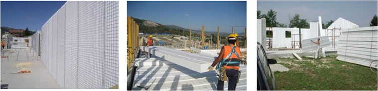
Figure 9. Examples of installation of formwork in site (courtesy of Nidyon Costruzioni).
RC Tubular Structures Made of Sandwich Walls: A Safe Solution for Developing Countries
The Structural System
During the last decades, the structural properties of a specific RC sandwich wall construction technology developed by a specific Italian company (Nidyon Costruzioni) have been extensively investigated at the University of Bologna.
The structural system is based on the production of prefabricated reinforced polystyrene panels (referred to as modular panels) with fixed length of 1,120 mm and height corresponding to the inter-storey building height. The panels are made of a single expanded polystyrene (EPS) layer with thickness between 60 and 160 mm, reinforced by two nets of Ø 2.5 mm steel wire mesh (spaced at 5 cm) anchored to the external faces through Ø 19 mm steel ties, that connect also the opposite nets. Once erected at the construction site, the modular panels act as support for the cast of the external 4 cm tick concrete layers (in most cases shotcrete). Additional reinforcements (usually 1 + 1 Ø 12 bar and Ø 8/500 mm U-shaped bars, made up of B450C steel) are added around the openings (doors and windows) and close to the edges of the wall (to provide extra strength along the side). The connections between the walls and the foundations are made through U-shaped Ø 8 mm anchor rods normally spaced at 500 mm (Palermo and Trombetti, 2016) (Figure 10).
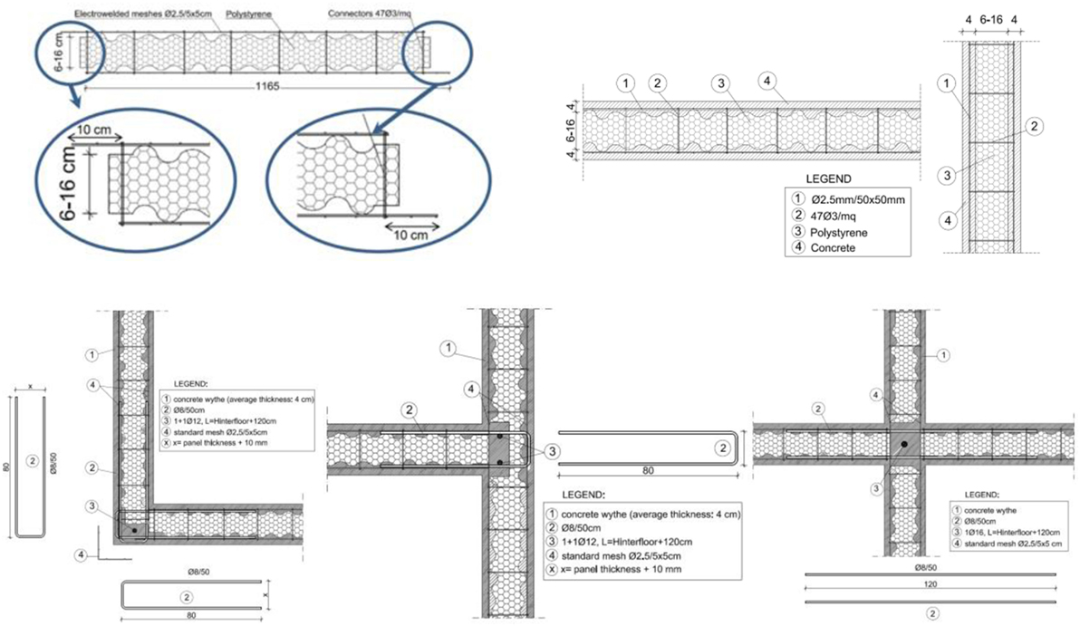
Figure 10. Top: typical dimensions of the sandwich panel (Palermo and Trombetti, 2016). Bottom: typical connections between orthogonal panels (Palermo and Trombetti, 2016).
The amount of reinforcement provided by the two steel meshes, together with the typical thickness of the two concrete layers, leads to a reinforcement ratio equal to 0.245% (e.g., the system can be classified as “Large Lightly Reinforced Concrete Walls,” according to (EC 8, 2005) EC8).
The solution allows to adequately couple thermal and structural performances as well as fast construction with reduced construction costs and appears particularly suitable for low-rise residential buildings, with squat structural walls characterized by an aspect ratio around 1.0. For instance, after the 2009 l’Aquila Earthquake, a complex of seven 3-storey base-isolated residential buildings (700 m2 surface) has been completed in 18 days using the Nidyon technology (Figure 11), with a construction cost in the order of 500 €/m2 (reconstruction plan “Piano C.A.S.E.”).
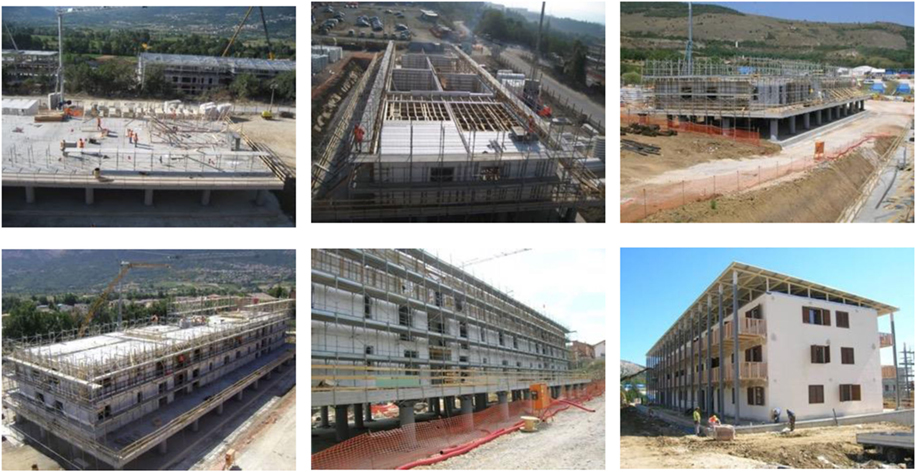
Figure 11. Work phases (“Piano C.A.S.E.”) (from the top left to the bottom right) day 1: work initiation; day 4: positioning of the slab modular panels; day 7: first floor completed; day 11: second floor completed; day 17: structure completed; day 73: building ready to be occupied (courtesy of Nidyon Costruzioni).
Seismic Behavior of RC Sandwich Walls: Summary of Past Studies
As abovementioned, the “Nidyon” structural solution is the result of a comprehensive research program that has been developed by the company in collaboration with the University of Bologna since the end of the 1990s. The most significant experimental tests (reports of all the experimental tests are available online on the “Nidyon Costruzioni s.p.a.” website: www.nidyon.com) conducted during the years include (i) tests at material level, (ii) test at single panel level: uniaxial compression tests (with and without eccentricity), diagonal compression tests, slip tests, and out-of-plane tests, (iii) connections tests (orthogonal walls and foundations), (iv) seismic tests on single panels (in-plane reversed cyclic tests of specimens with and without opening), (v) seismic tests on a full-scale H-shaped structure (in-plane reversed cyclic tests), and (vi) seismic tests on a full-scale 3-storey building (shaking-table tests at Eucentre Lab, Pavia).
As far as the seismic behavior of a single panel is concerned, the results of the pseudo-static tests revealed that the in-plane seismic response of a single RC sandwich panel is comparable (in terms of stiffness, strength, ductility) to that of conventional RC squat walls with similar dimensions and reinforcement ratios [the reader may refer to the tests conducted by Hidalgo et al. (2002)] (Figure 12). The main results of the experimental tests may be summarized as follows:
• the initial stiffness is approximately equal to 40 kN/mm and is consistent with the theoretical stiffness calculated considering an initial cracked cross section;
• the maximum strength increases with the applied axial load and it is in the range of about 300–370 kN;
• the equivalent damping ratio is slightly larger than 0.05 for low values of the drift (0.1–0.2%), while it is, on average, around 0.10 for mid-high values of the drift (0.4–1.0%);
• the displacement ductility capacity is at least equal to 4;
• the drift at yielding is approximately equal to 0.1%;
• the panels are able to withstand horizontal load up to inter-storey drift equal to 1.3% without loss of the vertical load-carrying capacity;
• the tested panels are able to withstand large horizontal loads (approximately 100 kN/m, which roughly corresponds to the elastic seismic demand of a 5-storey residential building located in a high-risk seismic zone).
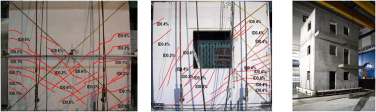
Figure 12. From the left: typical cracking patterns for a full panel and for a perforated panel; the prototype building tested on the shaking table at the Eucentre lab.
The shaking-table tests performed on the full-scale 3-storey building evidenced that the prototype building was able to sustain increasing levels of peak ground acceleration (PGA) up to 1.2 g without visible damages (Ricci et al., 2013; Palermo et al., 2014). More in detail, the results of the tests showed that:
• the prototype building exhibited a dynamic response in terms of fundamental frequency that can be simulated using a linear elastic FE model assuming partially cracked concrete conditions (i.e., an equivalent elastic modulus equal to approximately one half of the uncracked one);
• the prototype building exhibited “unexpected overstrengths” which were attributed to the pre-cracking concrete contribution in the shear strength (not manifested in the pseudo-static tests performed on the single panels).
All these results showed that the use of RC sandwich panels for low-rise buildings (assembled with adequate reinforcement at the connections between orthogonal walls and between walls and foundations so that a tubular behavior is guaranteed) leads to superior seismic performances (practically no damage under a severe earthquake) without particularly complex detailing and with quite competitive constructions costs.
Residential RC Sandwich Wall Buildings Designed in India
In 2016, a residential complex made of 4-storey buildings to be realized in Mumbai (India) has been designed by a local company in partnership with Nidyon Costruzioni srl using the sandwich panel technology presented in the previous section. The typical building is made of eight apartments per floor for a total number of 32 apartments per building. Each apartment has a total surface of 47 m2 as shown in Figure 13. The construction cost of the building can be estimated around 65 €/m2 and is in line with that of conventional residential buildings: the average construction cost to build a residential house including materials and labor cost with average finishes and bathroom/electrical accessories is around 200 €/m2, according to the online marketplace HAPPHO.5
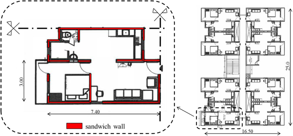
Figure 13. Typical apartment and typical floor of the residential buildings designed in Mumbai.
Case Study: Nepal’s School Buildings Made of RC Sandwich Walls
School Buildings Made by Smart Shelter Foundation
Between 2007 and 2012, Smart Shelter Foundation built 15 schools in Nepal, following general rules of thumb, which are commonly referred to as “best practice.” Two different techniques were used, namely, (i) hollow concrete blocks of 150 mm thickness and (ii) heavy and traditional rubble stone walls of 40 cm thickness. Manuals of the building sequences of these school designs can be obtained at Smart Shelter Foundation.6 It should be noted that all buildings have withstood the 2015 Gorkha earthquakes (7.9 magnitude) without any significant damage.
The typical three-classroom school building is characterized by 1:3 width versus length ratio with almost square classrooms of 5 m × 5 m dimensions, resulting in a maximum length of the total building volume of 15 m (Figure 14). In case, four or more classrooms are needed, they are divided in separate volumes of maximum three classrooms, with a gap in between the buildings (structural joint) of minimum 10 cm length.
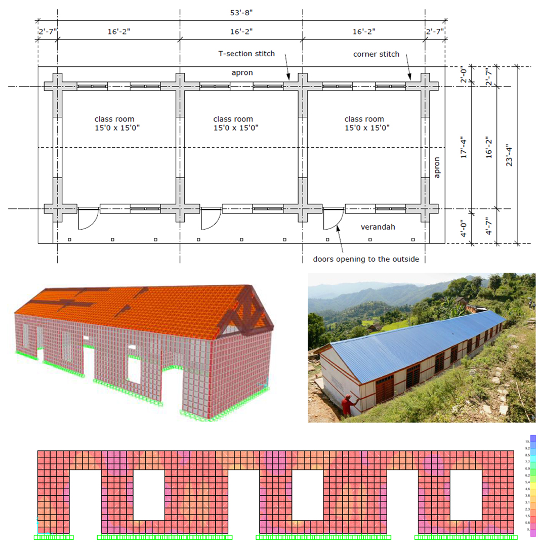
Figure 14. From top to bottom: plan of the three-classroom school building; FE model of the single block; photo of a two-block school (the blocks are separated by a 100 mm gap); envelope of the shear stress (kg/cm2) from time-history analysis.
Horizontal bands that tie up the walls are inserted at five different levels to provide additional lateral strength. The bands are typically inserted at (i) plinth beam foundation level, (ii) sill beam under the window level, (iii) stitches at the corners and t-sections, (iv) plinth beam over all doors and windows, and (v) top beam on top of the walls.
Both school designs follow these general rules of thumb:
• No more than 50% of wall openings are included, with sufficiently wide piers of at least 0.6 m, but preferably 0.9 m or more.
• For the heavy rubble stones, the preferred maximum wall height is 2.6 m, whereas the concrete block walls are maximum 3.0 m high.
The roof structure with tin sheets on top and ceiling below is made of wooden trusses that are placed on all end walls and interior walls. They are connected by rafters, purlins, and cross bracing so that the whole roof structure acts as a diaphragm, thus contributing to the box behavior of the building. One major difference between the two systems is the presence of vertical steel bars in the thinner walls with hollow cement blocks which are not inserted in the thick rubble stone walls. The vertical steel bars introduced in the buildings made by hollow cement block walls are placed in the corners, t-sections, and next to the openings. They are inserted to increase the wall flexural strength. As mentioned in the Section “Introduction,” as part of the technology transfer in the villages in Nepal, all drawings and details are provided in Nepali language. Moreover, after completion of the building, all earthquake-resistant measures are painted on the outside of the building, with explanation in Nepali text, so that the building becomes a full-size billboard for earthquake-resistant construction.
Seismic Performances of a School Buildings Made Out of Sandwich Panels
In this section, the seismic performances of the same school building designed by Smart Shelter Foundation but made of sandwich RC panels instead of rubber stones are investigated.
In fact, the use of ICFs would reach higher levels of seismic performance as well as thermal and acoustic insulation, still ensuring low construction cost and time, comparable to the traditional technique used to build the schools mentioned. Moreover, the ease of the construction process allows the use of local manpower, as part of the Smart Shelter Foundation philosophy, to spread the construction knowledge in developing countries and hazardous contexts.
The single panels have a total resistant thickness (e.g., the sum of the two external concrete layers) of 100 mm. The finite element model (developed using the commercial software SAP2000) of a single block of the typical school layout by Smart Shelter Foundation is represented in Figure 14.
The building model is subjected to the 1940 El Centro earthquake base acceleration (Imperial Valley record, PGA approximately equal to 0.3 g). Even though the seismic response of a building to a single earthquake ground motion cannot allow to derive conclusions of general validity, it is still a strong indication of a good or poor seismic behavior.
From the envelope of the maximum (absolute values) shear stresses in the longitudinal wall (Figure 14) it can be noted that the peak shear stresses are around 0.1–0.2 N/mm2, thus leading to first concrete cracking. The reduced values of the shear stresses obtained from the numerical time-history analysis are a first indication that the building performs in a good way under seismic excitation.
Conclusion
In this paper, a historical overview from the first frame structures to modern RC tubular structures realized with sandwich walls is provided within an Earthquake Engineering perspective. It is remarked that the first framed structures, which were introduced for freedom and versatility in the use of the spaces, showed all their limited seismic capacities before modern Earthquake Engineering was established as own discipline. The concept of ductility has been then introduced to overcome the intrinsic limited seismic capacity of framed structures. Soon it was realized that frame structures are not an adequate lateral resisting system for tall buildings, whereas wall structures with box-type behavior due to their geometrical configurations have potential superior structural performances when subjected to lateral loads. Such superior properties of box-type wall structures envisage a change of paradigm from the actual “ductility-based” Earthquake Engineering (centered on frame structures) toward a “strength-based” design, exploiting the use of box-type wall-based structures even for the case of low-rise buildings. Indeed, the use of this solution can easily yield to almost 100% safe buildings against earthquake, e.g., earthquake proof buildings. Finally, the use of modern construction techniques, such as ICFs can even allow to couple optimal structural performances with good insulating properties and reduced construction costs, thus resulting an appealing solution for constrictions to be realized in developing countries.
Author Contributions
VL, MP, and TT contributed in the review of the manuscript. MS contributed adding case studies and information on the work done in the developing countries.
Conflict of Interest Statement
The authors declare that the research was conducted in the absence of any commercial or financial relationships that could be construed as a potential conflict of interest.
Acknowledgments
The authors gratefully acknowledge the contributions of Nidyon Costruzioni srl (www.nidyon.com), Daniele Malavolta, Martijn Schildkamp (Smartshelter Research—www.smartshelterresearch.com), and Marco Gregori (Eco housing).
Footnotes
References
ACI Committee 549. (2010). Thin Reinforced Cementitious Products & Ferrocement. Washington DC: American Concrete Institution.
Ali, M. M., and Moon, K. S. (2007). Structural developments in tall buildings: current trends and future prospects. Archit. Sci. Rev. 50, 205–223. doi: 10.3763/asre.2007.5027
Bertero, R. D., and Bertero, V. V. (2002). Performance-based seismic engineering: the need for a reliable conceptual comprehensive approach. Earthq. Eng. Struct. Dyn. 31, 627–652. doi:10.1002/eqe.146
Billington, D. P. (1991). Robert Maillart and the Art of Reinforced Concrete. Cambridge, MA: MIT Press.
Bozorgnia, Y., and Bertero, V. V. (2004). Earthquake Engineering: From Engineering Seismology to Performance-Based Engineering. Boca Raton, FL: CRC Press.
Carpenter, L. D., Naeim, F., Lew, M., Youssef, N. F., Rojas, F., Saragoni, G. R., et al. (2011). Performance of tall buildings in Viña del Mar in the 27 February 2010 offshore Maule, Chile earthquake. Struct. Design Tall Spec. Build. 20, 17–36. doi:10.1002/tal.672
Casapulla, C., and Argiento, L. U. (2016). The comparative role of friction in out-of-plane mechanisms of masonry buildings. Pushover analysis and experimental investigation. Eng. Struct. 126, 158–173. doi:10.1016/j.engstruct.2016.07.036
EC 8. (2005). Eurocode 8: Design of Structures for Earthquake Resistance. Brussels: Commission of the European Communities.
Hidalgo, P. A., Ledezma, C. A., and Jordan, R. M. (2002). Seismic behavior of squat reinforced concrete shear walls. Earthq. Spectra 18, 287–308. doi:10.1193/1.1490353
Housner, G. (1984). An historical view of earthquake engineering. Revista de Ingeniería Sísmica 31, 1–16.
Khan, F. R. (1969). “Recent structural systems in steel for high-rise buildings,” in Proceedings of the British Constructional Steelwork Association Conference on Steel in Architecture, London, UK.
Khan, F. R. (1972). “Influence of design criteria on selection of structural systems for tall buildings,” in Proceedings of the Canadian Structural Engineering Conference, Montreal.
Khan, F. R. (1973). “Evolution of structural systems for high-rise buildings in steel and concrete,” in Tall Buildings in the Middle and East Europe: Proceedings of the 10th Regional Conference on Tall Buildings-Planning, Design and Construction (Bratislava: Czechoslovak Scientific and Technical Association).
Khan, F. R., and Sbarounis, J. A. (1964). Interaction of shear walls and frames. J. Struct. Div. 90, 285–338.
Khan, Y. S. (2004). Engineering Architecture: The Vision of Fazlur R. Khan, New York, NY: W. W. Norton & Company.
Lagos, R., Kupfer, M., Lindenberg, J., Bonelli, P., Saragoni, G. R., Guendelman, T., et al. (2012). Seismic performance of high-rise concrete buildings in Chile. Int. J. High Rise Build. 1, 181–194.
Palermo, M., Ricci, I., Silvestri, S., Gasparini, G., Trombetti, T., Foti, D., et al. (2014). Preliminary interpretation of shaking-table response of a full-scale 3-storey building composed of thin reinforced concrete sandwich walls. Eng. Struct. 76, 75–89. doi:10.1016/j.engstruct.2014.06.024
Palermo, M., and Trombetti, T. (2016). Experimentally-validated modelling of thin RC sandwich walls subjected to seismic loads. Eng. Struct. 119, 95–109. doi:10.1016/j.engstruct.2016.03.070
Parisi, F., and Augenti, N. (2012). Uncertainty in seismic capacity of masonry buildings. Buildings 2, 218–230. doi:10.3390/buildings2030218
Paulay, T., Priestley, M. J. N., and Synge, A. J. (1982). Ductility in earthquake resisting squat shearwalls. J. Proc. 79, 257–269.
Priestley, M. J. N., Calvi, G. M., and Kowalsky, M. J. (2007). “Direct displacement-based seismic design of structures,” in 2007 NZSEE Conference, Wellington.
Ricci, I., Palermo, M., Gasparini, G., Silvestri, S., and Trombetti, T. (2013). Results of pseudo-static tests with cyclic horizontal load on cast in situ sandwich squat concrete walls. Eng. Struct. 54, 131–149. doi:10.1016/j.engstruct.2013.03.046
SEAOC Vision 2000 Committee. (1995). Performance-Based Seismic Engineering. Report prepared by Structural Engineers Association of California: Sacramento, CA.
Smith, B. S., Coull, A., and Stafford-Smith, B. S. (1991). Tall Building Structures: Analysis and Design, Vol. 5. New York: Wiley.
Synge, A. J., Priestley, M. J. N., and Paulay, T. (1980). Ductility of Squat Shear Walls. Report No. 80-9. Christchurch, New Zealand: University of Canterbury, Department of Civil Engineering.
Wood, S. L. (1991). Performance of reinforced concrete buildings during the 1985 Chile earthquake: implications for the design of structural walls. Earthq. Spect. 7, 607–638. doi:10.1193/1.1585645
Moullier, T., and Krimgold, F. (2015). Building Regulation for Resilience: Managing Risks for Safer Cities. Washington, DC: World Bank.
Keywords: seismic-proof buildings, developing countries, box-type structure, insulating concrete forms, numerical modeling
Citation: Laghi V, Palermo M, Trombetti T and Schildkamp M (2017) Seismic-Proof Buildings in Developing Countries. Front. Built Environ. 3:49. doi: 10.3389/fbuil.2017.00049
Received: 20 April 2017; Accepted: 26 July 2017;
Published: 25 August 2017
Edited by:
Luigi Di Sarno, University of Sannio, ItalyReviewed by:
Claudia Casapulla, University of Naples Federico II, ItalyRita Bento, Universidade de Lisboa, Portugal
Copyright: © 2017 Laghi, Palermo, Trombetti and Schildkamp. This is an open-access article distributed under the terms of the Creative Commons Attribution License (CC BY). The use, distribution or reproduction in other forums is permitted, provided the original author(s) or licensor are credited and that the original publication in this journal is cited, in accordance with accepted academic practice. No use, distribution or reproduction is permitted which does not comply with these terms.
*Correspondence: Vittoria Laghi, vittoria.laghi2@unibo.it