Innovative Seismic Response-Controlled System with Shear Wall and Concentrated Dampers in Lower Stories
 Tsubasa Tani
 Ryota Maseki
 Izuru Takewaki
- 1Technology Center, Taisei Corp., Yokohama, Japan
- 2Department of Architecture and Architectural Engineering, Graduate School of Engineering, Kyoto University, Kyoto, Japan
A new structural control system using damper-installed shear walls in lower stories with reduced stiffness is proposed for vibration control of high-rise RC buildings. That system has some design variables, i.e., height of shear wall, degree of stiffness reduction at lower stories, and quantity of dampers. In this paper, some parametric studies on the shear-beam model with a stiff beam against two kinds of ground motion, a pulse-type sinusoidal wave and a resonant sinusoidal wave, are conducted to clarify the vibration characteristics of the proposed structural control system. It is shown that the optimal combination of design parameters depends on the input ground motion. It is also shown that it is possible to prevent from increasing the response under the one-cycle sinusoidal input resonant to the lowest mode and reduce the steady-state response under the harmonic input with the resonant fundamental period by reducing the stiffness in the lower structure and increasing the damper deformation.
Introduction
After the occurrence of unexpected earthquake damage, many structural engineers are striving for resilient building structures tough for extreme earthquake inputs and recoverable fast to an acceptable level (Bruneau and Reinhorn, 2006, Takewaki et al., 2012). It is aimed at trying to enhance the earthquake resilience of building structures via innovative technologies for broader classes of earthquake ground motions (Amadio et al., 2003, Kobori, 2004, Takewaki et al., 2012, 2013, Takewaki, 2013). In developing these innovative techniques, high uncertainty in earthquake ground motions may disturb the progress (Takewaki et al., 2011a,b, 2012, 2013, Takewaki, 2013). The variability and uncertainty in building structural properties (especially the properties of added control systems) should also be taken into account appropriately (Ben-Haim, 2006, Takewaki et al., 2011b).
In response to these circumstances, various kinds of vibration-controlled systems have been developed in the last three decades (Housner et al., 1997, Soong and Dargush, 1997, Hanson and Soong, 2001, Christopoulos and Filiatrault, 2006, Takewaki, 2009, Lagaros et al., 2013). Base-isolation systems, inter-story damper systems, inter-building damper systems (Fukumuto and Takewaki, 2015), and tuned-mass damper systems are representative examples. It is well known that the introduction of large deformation in the damper location is important in the inter-story damper systems and inter-building damper systems (Takewaki, 2009). This is because the large deformation in the damper location makes the damper systems effective.
Base-isolation systems have been employed mainly in Japan, New Zealand, China, and US. Various types of base-isolation systems have been introduced for pulse-type ground motions (Jangid and Datta, 1994; Hall et al., 1995; Heaton et al., 1995; Jangid, 1995; Kelly, 1999; Naeim and Kelly, 1999; Jangid and Kelly, 2001; Morales, 2003; Takewaki, 2005, 2008; Li and Wu, 2006; Hino et al., 2008; Takewaki and Fujita, 2009). But their resilience for earthquake has never been proved in actual situations for long-period ground motions with the characteristic period of 5–8 s (Irikura et al., 2004; Kamae et al., 2004; Ariga et al., 2006). This problem is closely associated with the resonance of the base-isolated buildings to those ground motions (Hashimoto et al., 2015). The long-period ground motions with 5–8 s characteristic periods were greatly concerned in the structural design of base-isolated buildings and super high-rise buildings after the Northridge earthquake in 1994 and the Tokachi-oki earthquake in 2003. Such input was shown as a key critical input for those kinds of buildings during the 2011 off the Pacific coast of Tohoku earthquake. It is also of great concern that, while building structures with passive dampers are effective for long-duration and long-period ground motions (Takewaki, 2007; Patel and Jangid, 2011; Takewaki et al., 2011b, 2012; Kasagi et al., 2015), their effectiveness for pulse-type ground motions is doubtful. This is because the structures with viscous-type dampers can not necessarily possess good performance for the impulsive input like near-fault ground motions resulting from the delay of response in such viscous-type dampers. The overcome of these two difficulties is of great significance in the seismic resistant and control design (Koo et al., 2009, Petti et al., 2010, Karabork, 2011).
Base isolation has been applied even to high-rise buildings. One is a base-isolated high-rise building without connection and the other is a base-isolated building connected to another structure with dampers (Murase et al., 2013, Kasagi et al., 2016, Fukumoto and Takewaki, 2017). In the latter connected system, a base-isolated high-rise building structure is linked to another non-isolated normal structure (free wall) with oil dampers. Because of the necessity of a substructure supporting the main building, high-rise residential apartment houses are the main object where a car parking tower is allocated as the substructure. The connected high-rise buildings without base isolation and base-isolated high-rise buildings connected to another structure have been designed and constructed by Obayashi Corporation and Shimizu Corporation in Japan (Murase et al., 2013, Kasagi et al., 2016, Fukumoto and Takewaki, 2017).
Historically tuned mass dampers (TMDs) have often been used for reducing building responses to wind loading and have been actually installed in many high-rise buildings (Soong and Dargush, 1997). It should be reminded that TMD is not effective for earthquake input because of the difficulty in stroke limitation and realization of large mass ratio TMD.
Nevertheless, large mass ratio TMDs have been explored mainly for earthquake inputs (Chowdhury et al., 1987; Feng and Mita, 1995; Arfiadi, 2000; Villaverde, 2000; Zhang and Iwan, 2002; Mukai et al., 2005; Villaverde et al., 2005; Tiang et al., 2008; Matta and De Stefano, 2009; Petti et al., 2010; Angelis et al., 2012; Nishii et al., 2013; Xiang and Nishitani, 2014). It should be pointed out that several projects are being planned in Japan aiming at installation of large mass pendulum systems at roof and usage of upper stories as TMD masses.
Recently, large mass ratio TMDs were tackled for base-isolated buildings (Villaverde, 2000; Villaverde et al., 2005; Angelis et al., 2012; Nishii et al., 2013; Xiang and Nishitani, 2014). While usual tall buildings exhibit large displacement near the top story because of contribution of almost uniform inter-story drifts, base-isolated buildings show relatively large displacement at the base-isolation story near ground surface. This property is very useful from the view point of reduction of effect of large vertical loads due to large mass ratio TMD (Kareem, 1997; Zhang and Iwan, 2002; Mukai et al., 2005; Petti et al., 2010; Nishii et al., 2013; Xiang and Nishitani, 2014). However, several issues still exist, e.g., avoidance of excessive vertical load by large mass ratio TMD, reduction of TMD stroke, and reduction of TMD support reactions (Hashimoto et al., 2015).
The use of a braced or mega-braced core is another effective method for improvement of structural responses under seismic loading (Brunesi et al., 2016). Furthermore, alternative solutions have been presented recently to obtain a kind of controlled structures by making use of dissipative devices called crescent-shaped braces (Palermo et al., 2014; Kammouh et al., 2017). Finally, a bracing system (called strongback system, SB) to control the deformed shape of framed structures subjected to seismic input is currently under development (Lai and Mahin, 2014). While these kinds of structural systems appear to be effective for long-period ground motions under the condition of possessing sufficient damper systems, the effectiveness for near-fault ground motions represented by pulse-type ground motions is not clear and further investigation may be necessary.
It is also important to develop methods for estimation of displacement and velocity profiles for framed structures with added dampers. The methods proposed by Palermo et al. (2015, 2016) are representative ones.
The present authors proposed a new vibration-controlled system in which large deformation in lower stories is induced and oil dampers are installed effectively (Tani et al., 2017). A similar study was conducted by Kazama and Mita (2006). In the previous research (Tani et al., 2017), the large deformation of oil dampers is obtained by the rigid rotation of shear walls. To ensure the safety in those lower stories, rigid shear-wall systems are introduced in the oil-damper installation system. Figure 1A shows the proposed vibration-controlled structure and Figure 1B presents the modeling of the structure with the proposed system into a multi-degree-of-freedom model and a reduced model. In the MDOF model, a rigid beam element (shear walls) with a pin connection at the bottom is connected to the main structure with rigid connectors. The added damping by the oil dampers is installed in the lower stories of the main structure. On the other hand, in the reduced model, the lower structure is modeled by a rigid bar supported by a rotational spring at the base and the lower structure is treated as a single-degree-of-freedom model in which the mass is concentrated at the point with the equivalent height.
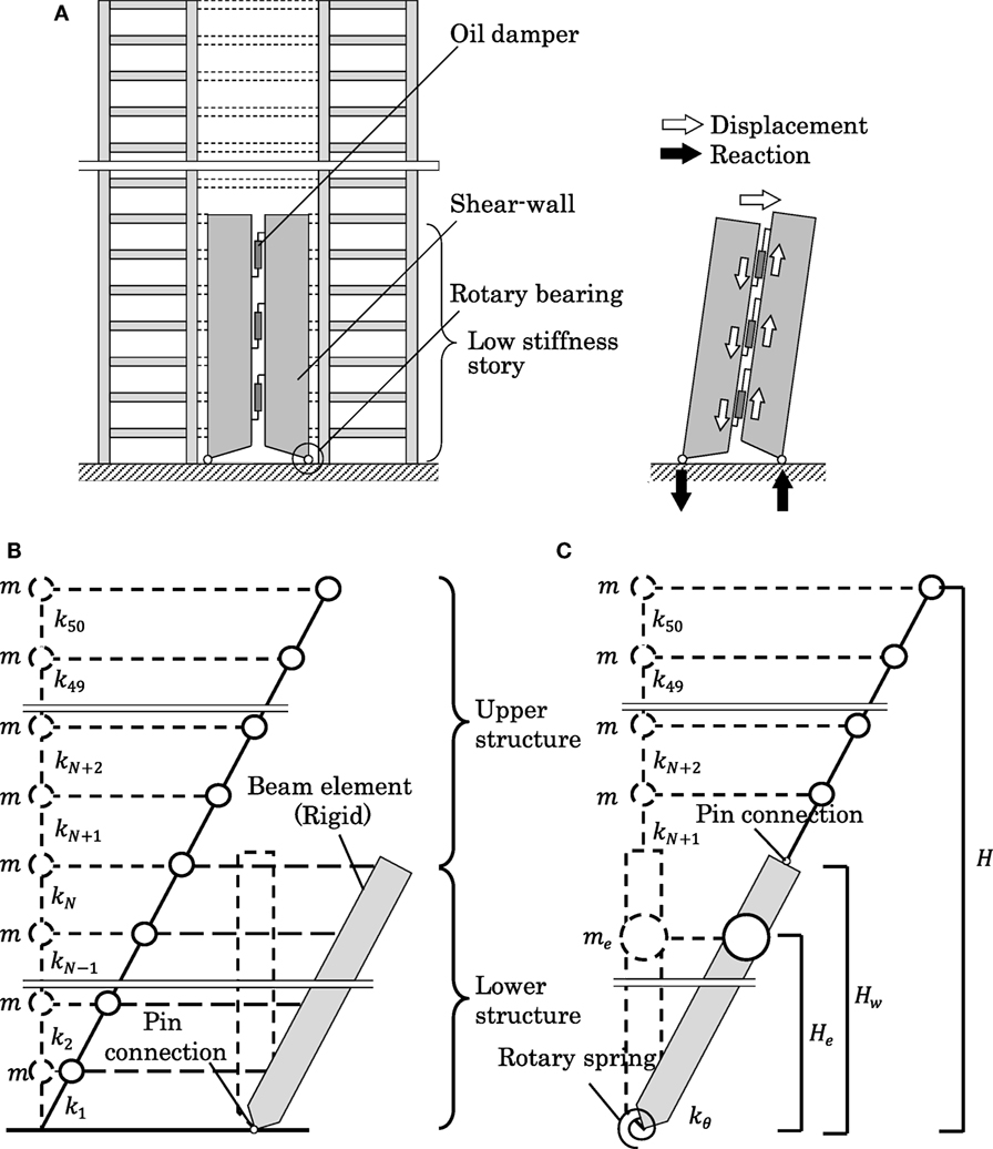
Figure 1. Proposed vibration-controlled structure and its modeling into multi-degree-of-freedom model and reduced model: (A) proposed system, (B) MDOF model, and (C) reduced model.
In this paper, parametric study on shear-beam model with stiff beam against two kinds of ground motion, pulsed sinusoidal wave and resonant sinusoidal wave, is conducted to clarify the vibration characteristics. It is shown that the optimal combination of variables depend on input ground motion, however, considering damper deformation growth by shear-wall, slight stiffness reduction at lower stories can achieve smaller story drift than proportional damping.
Natural Frequency and Mode of System with Shear Wall in Lower Stories
Basic Model and Reduced Model for Natural Vibration Analysis
Consider a 50-story shear building model, as shown in Figure 1B, which has an equal floor mass m at each story and an equal story height. The number of stories is an example of a high-rise building. The main structure is connected to a rigid bar (shear wall including dampers) with rigid connection. The model is assumed to have a straight-line lowest mode.
Since the analysis of the original model shown in Figure 1B seems difficult, a simpler model (equivalent to the model in Figure 1B) as shown in Figure 1C is introduced. Consider the lower structure in Figure 1B without the super structure (the lower part of the main structure and the rigid bar with rigid link). Let D, N, and Hw denote the top displacement of the lower structure, the number of stories of the lower structure, and the height of the lower structure, respectively. Furthermore, let me, He, and kθ denote the equivalent mass of the lower structure, the equivalent height of the lower structure, and the rotational stiffness of the spring at the base. When the fundamental natural circular frequency of the lower structure is denoted by , the lowest-mode i-th story shear force Qi of the lower structure in free vibration, the lowest-mode i-th story overturning moment Mi of the lower structure, the equivalent story shear Qe of the equivalent SDOF model, and the equivalent overturning moment Me of the equivalent SDOF model can be expressed by
By requiring the equivalence Q1 = Qe, M1 = Me in Eq. 1 in addition to the equivalence of the fundamental natural circular frequencies of the lower structure and its equivalent SDOF model, the equivalent quantities He, me and the rotational stiffness of the spring at the base can be derived as follows:
As N becomes large, He/Hw converges to 2/3 and me/(Nm) converges to 3/4.
Natural Frequency and Mode
The model shown in Figure 1C is used for the analysis of natural frequencies and modes. Figure 2A shows the change of natural periods to wall height (ratio of wall height to total height). The left figure is normalized to the fundamental natural period of the model without shear wall and the right one is normalized to each natural period of the model without shear wall. Since the lowest mode is straight, the fundamental natural period is not affected by the wall height. It can be observed that there is no influence until 0.2 and higher natural periods are affected much.
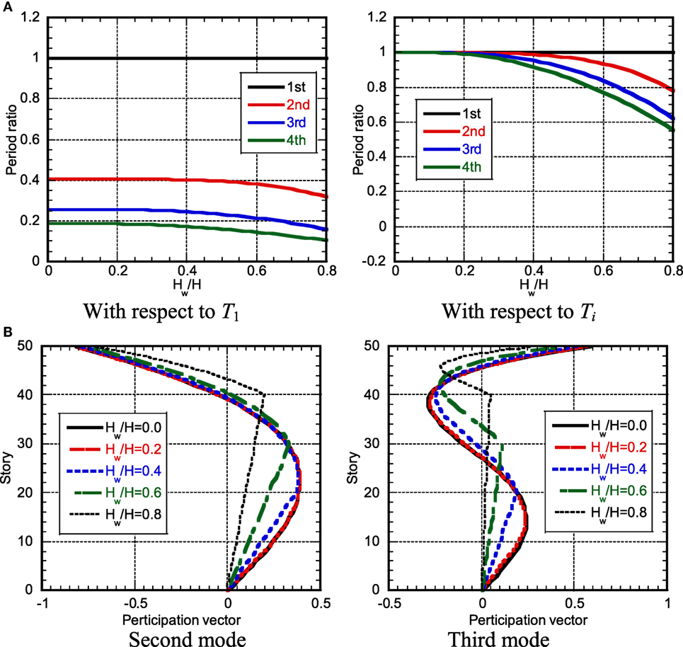
Figure 2. Change of natural period and participation vector to wall height: (A) change of natural period and (B) change of participation vector.
Figure 2B illustrates the change of participation vector to wall height. It can be seen that, as the wall height becomes larger, the lower-part higher-mode participation vectors remain straight and their slopes become smaller. On the other hand, the slopes of the upper-part higher-mode participation vectors become larger as the wall height becomes larger. However, its effect is small until Hw/H = 0.6 in the second mode and until Hw/H = 0.4 in the third mode.
Transfer Function
The model shown in Figure 1C is also used for the analysis of transfer functions. Figure 3 shows the transfer functions (top acceleration/base acceleration) for various wall heights. Figure 3A indicates those of the model with proportional damping (damping ratio: 0.03) and Figure 3B presents those of the model with concentrated damping in lower parts (total damping quantity is the same as the left one: damping ratio of 0.01 is distributed uniformly and the remaining damping ratio of 0.02 is concentrated in the lower parts). The damping ratio 0.03 is usually used in the design of reinforced concrete buildings and its comparable quantity of damping is given to the lower part of the present controlled buildings. The stiffness-proportional damping (proportional to overall structure or partial lower portion) is employed to represent the damping concentration appropriately. It can be seen in the model with proportional damping that, as Hw/H becomes larger, the amplitude at the second mode becomes smaller. This is because the higher-mode damping ratio becomes larger in the model with proportional damping. On the other hand, in the model with concentrated damping in lower parts, the amplitude at the second mode becomes larger. This is because the higher-mode deformation becomes smaller in lower parts as Hw/H becomes larger (see Figure 2B).
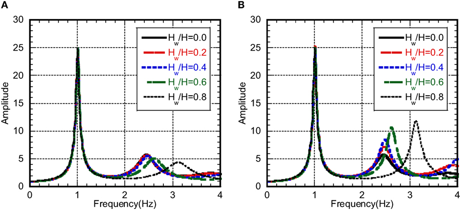
Figure 3. Transfer function: (A) proportional damping and (B) concentrated damping.
Response to Resonant One-Cycle Sinusoidal Pulse Wave
When the building with the proposed system is subjected to pulse-type ground motions, the energy dissipation by repeated vibration cannot be expected. In this case, the strict check of strength is important in the lower parts. In this section, the one-cycle sinusoidal waves resonant to the fundamental and second natural periods are input. The maximum response is evaluated by the mean of “the absolute sum of the maximum fundamental and second vibration components” and “the SRSS value.” The accuracy of this evaluation method will be investigated later.
Original Model and Comparison Model
In this section, a continuum shear-beam model with uniform mass density is dealt with in order to enable the closed-form mathematical treatment. A massless rigid bar with pin at the base is connected to this shear-beam model in the lower part. The lowest mode of the upper part is assumed based on data on the realistic high-rise building models.
Investigation Model
In most high-rise buildings, it is often the case that the inter-story drifts are almost uniform in the middle stories and they decrease toward the top and the bottom. Furthermore, in the proposed model, a rigid bar is installed in the lower part. Based on these information, the fundamental mode is assumed to be expressed by Eq. 3:
where
In Eq. 3, Hw, Hl, and Ht(=H) denote the height of the lower part, the height of the part with straight fundamental mode, and the building total height and indicate the displacements of the fundamental mode at Hw, Hl, Ht, and the slopes of the fundamental mode at Hw, Hl, Ht. and indicate the ratio of the slope at x = Hw (top of the lower structure) of the lowest mode to that at x = Hl (the top of straight-line lowest-mode shape) and the ratio of the slope at x = Ht (top of the upper structure) of the lowest mode to that at x = Hl. In this investigation, it is assumed that Hl/Ht = 0.6 and . The structural damping is assumed to be stiffness-proportional over the whole height and the additional damping is added only to the lower part as stiffness-proportional one.
Comparison Model
The fundamental mode has the property of Eq. 3 with Hl/Ht = 0.6, , and . The comparison model does not have the rigid bar in the lower part. The structural damping and the additional damping are the same as the investigation model. However, the additional damping is distributed over the total height. The quantities of the comparison model are designated by the over-bar.
Stiffness
The sum of the story stiffnesses in the upper part is the same between the investigation model and the comparison model. The sums of the story stiffnesses in the lower part and their distributions are different depending on the adopted mode. In case of , the sum of the story stiffnesses of the whole part in the investigation model becomes larger than that of the comparison model. Then, the fundamental natural period becomes longer.
Damping
Since the structural damping is the stiffness-proportional one, the sum of damping coefficients of the model becomes smaller for the model with a smaller sum of the story stiffnesses in the lower part and longer fundamental natural period. The additional damping coefficients are assumed not to change.
The relations of mass, stiffness, and damping between the investigation model and the comparison model are expressed as follows:
where m(x), k(x), c(x), Δc(x), and are the mass, stiffness, structural damping coefficient, and additional damping coefficient distributions of the investigation model and the comparison model, respectively. In addition, M is the total mass.
Figure 4 shows an example of the fundamental mode and its story drift angle.
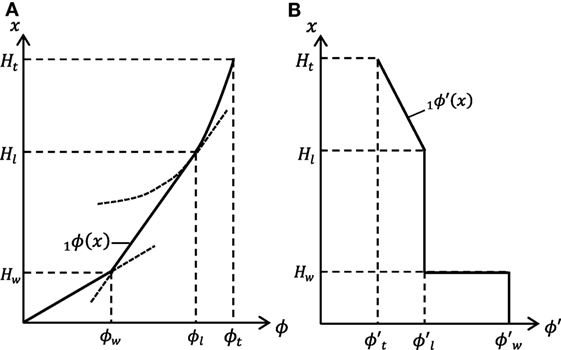
Figure 4. Fundamental mode and its story drift angle: (A) fundamental mode shape and (B) story drift angle.
Model to Be Considered (Investigated Region of Fundamental Mode Shape)
Realistic models are considered here. Figure 5 shows the investigated region of the fundamental mode shape with Hw and as parameters. 0.2Ht ≤ Hw ≤ 0.6Ht and are considered here.
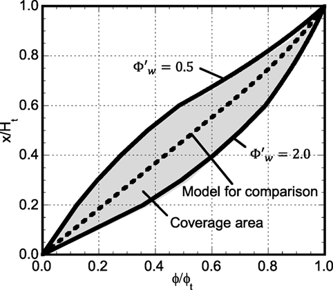
Figure 5. Investigated region of fundamental-mode shape.
The additional damping quantity is defined as the sum of the damping coefficients in the comparison model with a stiffness-proportional damping of the lowest-mode damping ratio . In the investigation model, the additional damping coefficients with the same value of are allocated to the lower part.
Damping Coefficient of Added Damper and Second Natural Frequency and Mode
Fundamental Mode
When the fundamental mode is expressed by
the dynamic equilibrium of the part from x to Ht can be described by
Substitution of Eqs. 3 and 6a into Eq. 6b leads to the following form of stiffness.
The structural damping coefficient of the investigation model can then be expressed by
Consider the additional damping coefficient of the investigation model. First of all, the stiffness and structural damping coefficient of the comparison model can be obtained by substituting into Eqs 7 and 8 (then D = F, E = 0):
Similarly, the additional damping coefficient of the comparison model can be expressed by
The sum of the additional damping coefficients of the comparison model can then be obtained as
Since the additional damping coefficient of the investigation model is given only at the lower parts as one proportional to the corresponding stiffness, the additional damping coefficient of the investigation model is expressed as follows:
Equations 7 and 12 should be substituted into Eq. 13. The fundamental natural circular frequency of the investigation model can be determined from the condition that the sum of the stiffnesses in the upper part is constant in the investigation model. The sums of the stiffnesses in the upper parts of the investigation model and the comparison model are expressed by
where is the function derived by substituting Eq. 7 into the left-hand side of Eq. 14 and is the function derived by substituting Eq. 9 into the left-hand side of Eq. 15. By equating Eqs 14 and 15, the fundamental natural circular frequency of the investigation model can be obtained as follows:
The lowest-mode additional damping ratio of the investigation model is predicted approximately by using the undamped lowest mode. Using Eq. 3, can then be evaluated by
Second Mode
It is known that the second mode of a shear-beam with uniform mass density and a straight-line fundamental mode can be expressed by a cubic function in the comparison model. However, some modification is necessary in the investigation model. For this reason, the second mode above the point x = Hw is modeled by an L-th order function (L = 5 is employed here). Then, the second mode can be expressed by
The slope of the second mode can be obtained as
The dynamic equilibrium of the part from x = Hw to Ht can be described by
for . L points have been used to determine L coefficients. When aL is treated as a given value, are obtained to be the L-th order polynomials of . By using Eqs 7 and 19, the continuity condition of the story shear force at x = Hw leads to
satisfying Eq. 21 is regarded as an approximate value of the second natural frequency.
The second damping ratio of the investigation model is evaluated by using an undamped second natural mode. The additional damping ratios (the additional damping quantity D2%) of the investigation model for various shear wall heights are shown in Figure 6A with respect to for the fundamental mode and in Figure 6B for the second mode. It can be understood that the fundamental additional damping ratio becomes larger than that for the proportional damping case as the stiffness in the lower part decreases. On the other hand, the second additional damping ratio depends greatly on Hw. While it increases as the stiffness in the lower part decreases in the case of small values of Hw, it is almost constant irrespective of the stiffness in the lower part in the case of large values of Hw.
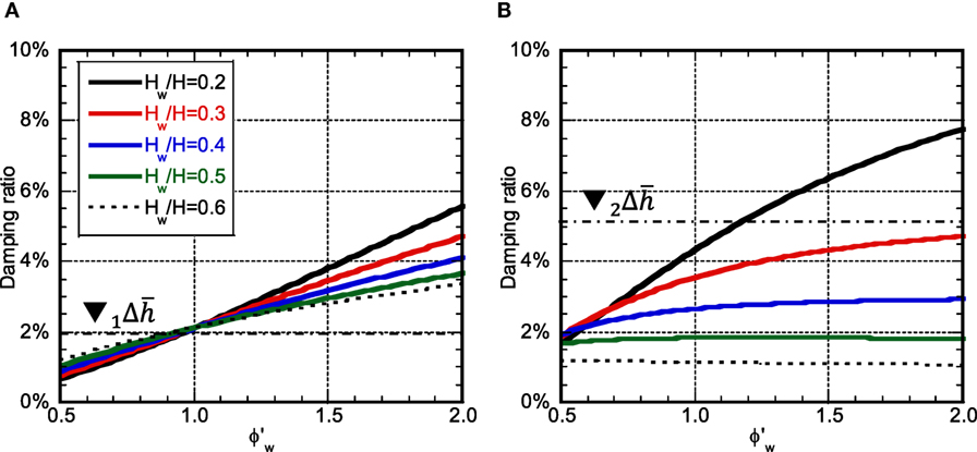
Figure 6. Damping ratio with respect to : (A) first mode and (B) second mode.
Maximum Response Displacement
Consider the maximum story drift angle of the model subjected to the resonant (first mode and second mode) one-cycle sinusoidal wave with constant velocity amplitude of 1 m/s. The total response is evaluated approximately by superposing the first and second mode vibrations. The maximum response is evaluated by the mean of the absolute sum of the first and second mode vibrations and the SRSS value.
The displacement response of the SDOF model under a one-cycle sinusoidal acceleration wave is well known (Clough and Penzien, 1975, Yasui et al., 2010) and can be expressed by
where are the undamped natural circular frequency, the damped natural circular frequency, and the damping ratio and X, Y are given by
Equation 22 is the solution during the input and the response after the input can be expressed in terms of free vibration. The time at which the maximum displacement occurs in the undamped model is expressed by the following one (Kamei et al., 2010):
where T is the natural period of the SDOF model, n is a positive integer satisfying tdmax ≤ Tp, and k is a positive integer satisfying tdmax ≥ Tp. Therefore, this expression is used approximately for damped vibration.
Since the lower structure exhibits a straight-line displacement due to the existence of the rigid shear wall, the story drift angle shows a constant distribution. In case of , the lowest mode exhibits the maximum story drift angle in the upper structure in Hw < x ≤ Hl and the second mode exhibits the maximum story drift angle in the upper structure at x = Ht. Let and denote the j-th mode maximum story drift angle at x of the investigation model subjected to the one-cycle sinusoidal input resonant to the mode i and that of the comparison model. Furthermore, let and denote the maximum story drift angle of the investigation model subjected to the one-cycle sinusoidal input resonant to the mode i and that of the comparison model.
Resonant Wave to First Mode
Figures 7A–C show , , and and Figure 7D presents for the structural damping ratio 0.01 and the additional damping quantity D2%. It should be noted that the story drift angles are expressed under the condition of Ht = 1. (If the fundamental natural period = 1.0 s and the total height = 40 m, the number 60 in the vertical axis means 0.015 rad.) It can be observed that the influence of the second mode is small and its small effect exists only around the top. As the stiffness of the lower structure decreases, the story drift angle in the upper structure becomes small and the story drift angle in the lower structure increases. This phenomenon is prominent for the larger value of Hw in the upper structure and for the smaller value of Hw in the lower structure. The model with the original stiffness distribution exhibits the smallest value irrespective of Hw and this value is almost the same as the comparison model. It can also be seen that the increase of additional damping in the lower structure cannot prevent the response amplification due to the reduction of the stiffness in the lower structure.
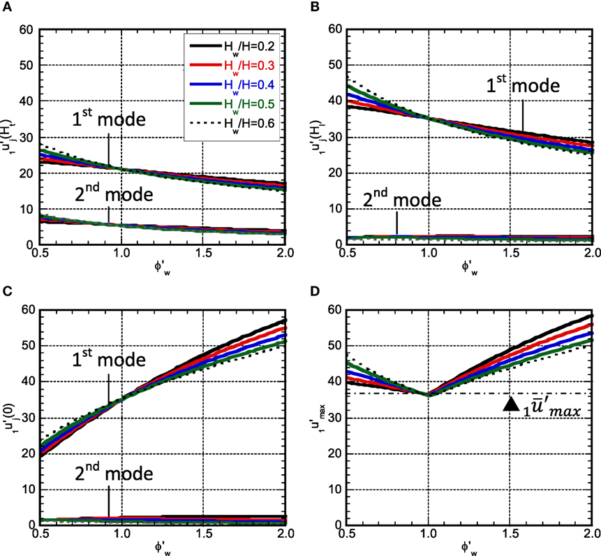
Figure 7. Maximum story drift angle for lowest-mode resonance pulse: (A) , (B) , (C) , and (D) .
Resonant Wave to Second Mode
Figures 8A–C show , , and and Figure 8D presents for the structural damping ratio 0.01 and the additional damping quantity D2%. It can be observed that, although the response by the second mode becomes larger than that by the fundamental mode around the top, the response by the fundamental mode becomes dominant except around the top. Since the difference of the fundamental and second natural periods becomes large as Hw becomes large, the response exhibits a different property even if the lowest mode shape is the same . Since the effect of the second mode becomes small as the stiffness in the lower structure becomes small, the response in the lower structure due to the second mode does not become larger. The region exists where the response of the investigation model becomes smaller than that of the comparison model. This region becomes wider as Hw becomes larger.
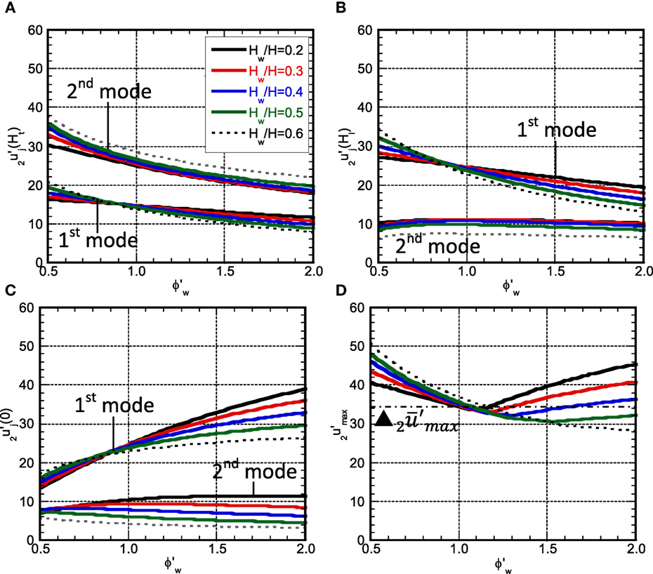
Figure 8. Maximum story drift angle for second-mode resonance pulse: (A) , (B) , (C) , and (D) .
Accuracy Check by Time–History Response Analysis for MDOF Model
Figure 9 shows the comparison of the maximum story drift angles by the proposed method with those by the MDOF model as shown in Figure 1B. It can be observed that, although the proposed estimation gives a slightly larger response under the input resonant to the lowest mode, the accuracy is almost satisfactory. On the other hand, the proposed estimation provides a slightly smaller response under the input resonant to the second mode in . This is because the maximum story drift angle becomes the largest at the top and the third-mode effect at the top becomes large compared to the response in the lower structure. In addition, the third-mode vibration is easy to be induced in the response resonant to the second mode than that resonant to the lowest mode.
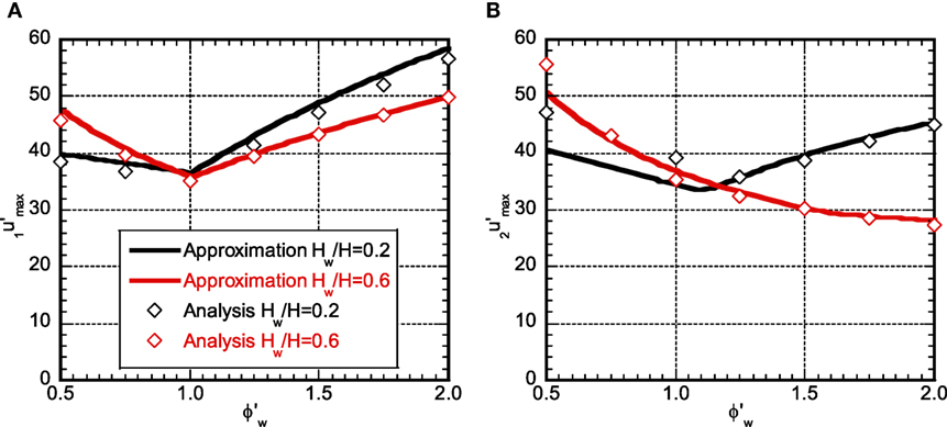
Figure 9. Comparison of approximation with time-history response analysis: (A) and (B) .
Effect of Damping
Figure 10 shows the maximum story drift angle with respect to under various damping quantities for Hw/H = 0.4. It can be observed that, although the response reduction is possible by the introduction of the additional damping, its effect is small. When the stiffness in the lower structure is reduced, the response reduction effect becomes larger slightly. Furthermore, when the stiffness in the lower structure is reduced, the response under the one-cycle sinusoidal wave resonant to the lowest mode becomes larger than that under the one-cycle sinusoidal wave resonant to the second mode.
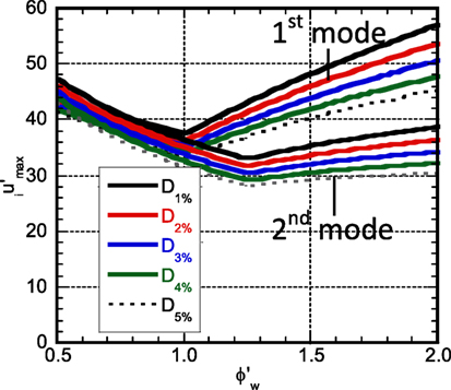
Figure 10. Maximum story drift angle under various damping quantities (Hw/H:0.4).
When the stiffness in the lower structure is reduced, the response of the investigation model under the one-cycle sinusoidal wave resonant to the lowest mode becomes larger than that of the comparison model. The proposed model has an advantage that the reduction of the stiffness in the lower structure enhances the performance of the dampers. Figure 11 presents the necessary damper deformation growth rate with respect to ϕw under various shear-wall heights for D2% and D5%. As the damper quantity becomes larger, the necessary damper growth rate becomes smaller. The influence of Hw is very small.
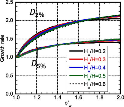
Figure 11. Necessary damper deformation growth rate.
Steady-State Response to Resonant Harmonic Base Input
Since the long-period, long-duration ground motions can be represented approximately by long-duration sinusoidal waves and steady-state vibrations are predominant in such vibration, the resonant input to the fundamental natural period is considered here.
Reduction of Original Model into 2DOF Model
It is well known that, since the steady-state response to the resonant harmonic input can be influenced greatly by the magnitude and distribution of damping in the structure, it may be difficult to use the undamped vibration mode for response evaluation. For this reason, the shear beam treated in the previous section is reduced to the 2DOF model in which one mass is located at x = Hw = H1 and the other mass is located at x = H2. The accuracy of this model will be investigated later. The height H2 is determined from the equivalence of the participation vectors of these two models. In addition, the fundamental natural frequencies, the participation vectors at x = Hw, the lowest-mode story shears at x = 0, Hw are made equal (see Figure 12: equivalence conditions). The damping coefficients are determined so that the energy dissipations by the damping are equal. The parameters are Hw, , and .
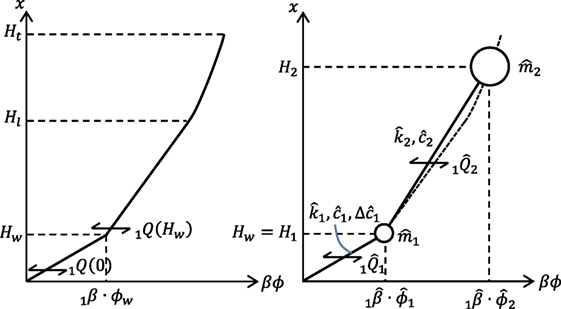
Figure 12. Correspondence of participation vectors and story shear forces between shear-beam model and 2DOF model.
Parameter of Reduced 2DOF Model
Let denote the lowest-mode participation factor of the shear-beam model. The masses, stiffnesses, and damping coefficients of the reduced 2DOF model can be expressed as follows in terms of the parameters Hw and from the equivalence conditions introduced just above:
The quantities with that indicate the quantities of the 2DOF model. The additional damping coefficient in the lower part can be obtained as
The story shear at x = Hw in the lowest mode of the shear-beam model may be expressed by
The height H2 at which the equivalence of the participation vectors of the two models, i.e., , is satisfied can be derived as
where A, B, C have been defined in Eq. 3.
Maximum Response Displacement
The amplitude of the steady-state displacement of the 2DOF model under the harmonic input with constant velocity amplitude is computed for various shear wall heights. These values are drawn with respect to the parameter .
Figure 13A shows the ratio of the story drift angle in the upper structure of the investigation model to that of the comparison model under various shear-wall heights for the additional damping level of D2% and Figure 13B presents the corresponding one in the lower structure. Figures 13C,D illustrate the corresponding ones for the additional damping level of D5%.
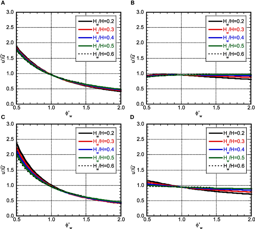
Figure 13. Maximum story drift angle ratio (variable: Hw/H): (A) upper structure (D2%), (B) lower structure (D2%), (C) upper structure (D5%), and (D) lower structure (D5%).
Figure 14A shows the ratio of the story drift angle in the upper structure of the investigation model to that of the comparison model under various additional damping levels for the shear-wall height of Hw/Ht = 0.2 and Figure 14B presents the corresponding one in the lower structure. Figures 14C,D illustrate the corresponding ones for the shear-wall height of Hw/Ht = 0.5.
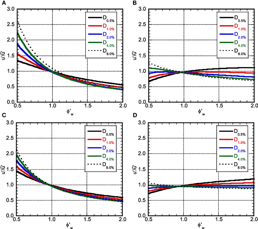
Figure 14. Maximum story drift angle ratio (variable: ): (A) upper structure (Hw/H:0.2), (B) lower structure (Hw/H:0.2), (C) upper structure (Hw/H:0.5), and (D) lower structure (Hw/H:0.5).
It can be observed that, as the stiffness in the lower structure decreases, the story drift angle in the upper structure also decreases. While the story drift angle in the lower structure also decreases according to the decrease of the stiffness in the lower structure in the case of large additional damping in the lower structure, it increases in the case of small additional damping in the lower structure. This means that the effect of response reduction due to the damping in the steady-state vibration is larger than the effect of response amplification due to the stiffness reduction in the case where a certain level of additional damping is introduced. Furthermore, the influence of Hw on the response is rather small.
Figure 15 presents the comparison of the time–history analysis result by the 2DOF model with that by the MDOF model. “2DOF upper” indicates the maximum story drift angle in the upper structure by the 2DOF model and “MDOF upper” means that by the MDOF model. Furthermore, “2DOF lower” indicates the maximum story drift angle in the lower structure by the 2DOF model and “MDOF lower” means that by the MDOF model. It can be seen that the accuracy of the 2DOF model is satisfactory.
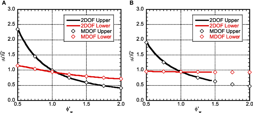
Figure 15. Comparison of time–history responses between 2DOF and MDOF: (A)Hw/H:0.2, D5% and (B)Hw/H:0.6, D5%.
Conclusion
A new structural control system using damper-installed shear walls with a pin connection at the bottom has been proposed for vibration control of high-rise RC buildings. The response analysis for one-cycle sinusoidal ground motions resonant to the lowest and second natural modes and for the harmonic ground motion has been performed. The obtained results are summarized as follows.
(1) The lowest-mode component is predominant in the response resonant to the lowest mode and the maximum response becomes the smallest in the model with a straight-line lowest mode. It is more effective to control the stiffness and the mode shape than concentrating the additional dampers into the location with larger story drift angles (see Figure 7).
(2) The lowest-mode component is predominant in the response of the lower structure resonant even to the second mode. Since the difference of the fundamental and second natural periods becomes large as Hw becomes large, the lowest mode is hard to be induced and the response in the lower structure becomes smaller (see Figure 8). It may be possible to reduce the response by decreasing the stiffness in the lower structure.
(3) The steady-state vibration resonant to the lowest mode becomes smaller by reducing the stiffness in the lower structure (see Figure 13). However, the region exists that the response becomes larger partially when the additional damping quantity is extremely small.
(4) Since the rigid shear wall makes the story drift angle distribution uniform and reduces the maximum response, the response amplification by the second mode in the lower structure is prevented as Hw becomes large. For this reason, when the additional dampers are concentrated in the lower part, the second damping ratio becomes smaller compared to the stiffness-proportional damping model and it does not increase even if the stiffness in the lower structure is reduced (see Figures 2B and 6B).
(5) It may be possible to prevent from increasing the response under the one-cycle sinusoidal input resonant to the lowest mode and reduce the steady-state response under the harmonic input with the resonant fundamental period by reducing the stiffness in the lower structure and increasing the damper deformation (see Figure 11).
(6) The maximum response evaluation under the resonant one-cycle sinusoidal input using the undamped natural modes is accurate and reliable. However, as the higher-mode effect becomes larger, the accuracy may deteriorate slightly (see Figure 9).
(7) The response amplitude evaluation under the harmonic input can be made within a reliable accuracy by using the 2DOF model which is reduced from the shear-beam model (see Figure 15).
Author Contributions
TT carried out the theoretical and numerical analysis. RM carried out the theoretical investigation. IT supervised the theoretical analysis.
Conflict of Interest Statement
The authors declare that the research was conducted in the absence of any commercial or financial relationships that could be construed as a potential conflict of interest.
The reviewer MP and handling editor declared their shared affiliation.
References
Amadio, C., Fragiacomo, M., and Rajgelj, S. (2003). The effects of repeated earthquake ground motions on the non-linear response of SDOF systems. Earthq. Eng. Struct. Dyn. 32, 291–308. doi: 10.1002/eqe.225
Angelis, M. D., Perno, S., and Reggio, A. (2012). Dynamic response and optimal design of structures with large mass ratio TMD. Earthq. Eng. Struct. Dyn. 41, 41–60. doi:10.1002/eqe.1117
Arfiadi, Y. (2000). Optimal Passive and Active Control Mechanisms for Seismically Excited Buildings. Ph.D. Dissertation, University of Wollongong, Austria.
Ariga, T., Kanno, Y., and Takewaki, I. (2006). Resonant behavior of base-isolated high-rise buildings under long-period ground motions. Struct. Des. Tall Spec. Build. 15, 325–338. doi:10.1002/tal.298
Ben-Haim, Y. (2006). Information-Gap Decision Theory: Decisions under Severe Uncertainty. London: Academic Press.
Bruneau, M., and Reinhorn, A. (2006). “Overview of the resilience concept,” in Proc. of the 8th US National Conference on Earthquake Engineering, San Francisco.
Brunesi, E., Nascimbene, R., and Casagrande, L. (2016). Seismic analysis of high-rise mega-braced frame-core buildings. Eng. Struct. 115, 1–17. doi:10.1016/j.engstruct.2016.02.019
Chowdhury, A. H., Iwuchukwu, M. D., and Garske, J. J. (1987). “The past and future of seismic effectiveness of tuned mass dampers,” in Structural Control, ed. H. H. E. Leipholz (Ontario: Martinus Nijhoff Publishers), 105–127.
Christopoulos, C., and Filiatrault, A. (2006). Principle of Passive Supplemental Damping and Seismic Isolation. Italy: IUSS Press, University of Pavia.
Feng, M. Q., and Mita, A. (1995). Vibration control of tall buildings using mega subconfiguration. J. Eng. Mech. 121, 1082–1088. doi:10.1061/(ASCE)0733-9399(1995)121:10(1082)
Fukumoto, Y., and Takewaki, I. (2017). Dual control high-rise building for robuster earthquake performance. Front. Built Environ. 3:12. doi:10.3389/fbuil.2017.00012
Fukumuto, Y., and Takewaki, I. (2015). Critical demand of earthquake input energy to connected building structures. Earthq. Struct. 9, 1133–1152. doi:10.12989/eas.2015.9.6.1133
Hall, J. H., Heaton, T. H., Halling, M. W., and Wald, D. J. (1995). Near-source ground motion and its effect on flexible buildings. Earthq. Spectra 11, 569–605. doi:10.1193/1.1585828
Hanson, R. D., and Soong, T. T. (2001). Seismic Design with Supplemental Energy Dissipation Devices. Oakland, CA: EERI.
Hashimoto, T., Fujita, K., Tsuji, M., and Takewaki, I. (2015). Innovative base-isolated building with large mass-ratio TMD at basement. Int. J. Future Cities Environ. 1, 9. doi:10.1186/s40984-015-0007-6
Heaton, T. H., Hall, J. H., Wald, D. J., and Halling, M. W. (1995). Response of high-rise and base-isolated buildings in a hypothetical MW 7.0 blind thrust earthquake. Science 267, 206–211. doi:10.1126/science.267.5195.206
Hino, J., Yoshitomi, S., Tsuji, M., and Takewaki, I. (2008). Bound of aspect ratio of base-isolated buildings considering nonlinear tensile behavior of rubber bearing. Struct. Eng. Mech. 30, 351–368. doi:10.12989/sem.2008.30.3.351
Housner, G., Bergaman, L. A., Caughey, T. K., Chassiakos, A. G., Claus, R. O., Masri, S. F., et al. (1997). Special issue, structural control: past, present, and future. J. Engng. Mech. ASCE 123, 897–971. doi:10.1061/(ASCE)0733-9399(1997)123:9(897)
Irikura, K., Kamae, K., and Kawabe, H. (2004). “Importance of prediction of long-period ground motion during large earthquakes,” in Annual Conference of the Seismological Society of Japan, Poster Session, Fukuoka.
Jangid, R. S. (1995). Optimum isolator damping for minimum acceleration response of base-isolated structures. Aust. Civil Eng. Trans. 37, 325–331.
Jangid, R. S., and Datta, T. K. (1994). Non-linear response of torsionally coupled base isolated structure. J. Struct. Eng. 120, 1–22. doi:10.1061/(ASCE)0733-9445(1994)120:1(1)
Jangid, R. S., and Kelly, J. M. (2001). Base isolation for near-fault motions. Earthq. Eng. Struct. Dyn. 30, 691–707. doi:10.1002/eqe.31
Kamae, K., Kawabe, H., and Irikura, K. (2004). “Strong ground motion prediction for huge subduction earthquakes using a characterized source model and several simulation techniques,” in Proceedings of the 13th WCEE (Vancouver).
Kamei, I., Sato, K., and Hayashi, Y. (2010). Evaluation based on modal analysis of response drift in MDOF systems subjected to pulse-wave ground motions. J. Struct. Construct. Eng. 649, 567–575. doi:10.3130/aijs.75.567
Kammouh, O., Silvestri, S., Palermo, M., and Cimellaro, G. P. (2017). Performance-based seismic design of multistory frame structures equipped with crescent-shaped brace. Struct. Control Health Monitor. doi:10.1002/stc.2079
Karabork, T. (2011). Performance of multi-storey structures with high damping rubber bearing base isolation systems. Struct Eng Mech. 39, 399–410. doi:10.12989/sem.2011.39.3.399
Kareem, A. (1997). Modelling of base-isolated buildings with passive dampers under winds. J. Wind Eng. Indus. Aerodyn. 72, 323–333. doi:10.1016/S0167-6105(97)00232-8
Kasagi, M., Fujita, K., Tsuji, M., and Takewaki, I. (2015). Effect of nonlinearity of connecting dampers on vibration control of connected building structures. Front. Built Environ. 1:25. doi:10.3389/fbuil.2015.00025
Kasagi, M., Fujita, K., Tsuji, M., and Takewaki, I. (2016). Automatic generation of smart earthquake-resistant building system: hybrid system of base-isolation and building-connection. J. Heliyon 2, 2. doi:10.1016/j.heliyon.2016.e00069
Kazama, H., and Mita, A. (2006). Effective arrangement of passive control systems in structures considering complex modal characteristics. J. Struct. Construct. Eng. 599, 23–28. doi:10.3130/aijs.71.23_1
Kelly, J. M. (1999). The role of damping in seismic isolation. Earthq. Eng. Struct. Dyn. 28, 3–20. doi:10.1002/(SICI)1096-9845(199901)28:1<3::AID-EQE801>3.3.CO;2-4
Koo, J.-H., Jang, D.-D., Usman, M., and Jung, H.-J. (2009). A feasibility study on smart base isolation systems using magneto-rheological elastomers. Struct. Eng. Mech. 32, 755–770. doi:10.12989/sem.2009.32.6.755
Lagaros, N. D., Plevris, V., and Mitropoulou, C. (eds) (2013). Design Optimization of Active and Passive Structural Control Systems. Hershey, PA, USA: IGI Global.
Lai, J. W., and Mahin, S. A. (2014). Strongback system: a way to reduce damage concentration in steel-braced frames. J. Struct. Eng. 141, 04014223. doi:10.1061/(ASCE)ST.1943-541X.0001198
Li, H.-N., and Wu, X.-X. (2006). Limitations of height-to-width ratio for base-isolated buildings under earthquake. Struct. Des. Tall Spec. Build. 15, 277–287. doi:10.1002/tal.295
Matta, E., and De Stefano, A. (2009). Robust design of mass-uncertain rolling-pendulum TMDs for seismic protection of buildings. Mech. Syst. Sig. Process. 23, 127–147. doi:10.1016/j.ymssp.2007.08.012
Morales, C. A. (2003). Transmissibility concept to control base motion in isolated structures. Eng. Struct. 25, 1325–1331. doi:10.1016/S0141-0296(03)00084-1
Mukai, Y., Fujimoto, M., and Miyake, M. (2005). A study on structural response control by using powered-mass couplers system. J. Struct. Eng. 51B, 225–230.
Murase, M., Tsuji, M., and Takewaki, I. (2013). Smart passive control of buildings with higher redundancy and robustness using base-isolation and inter-connection. Earthq. Struct. 4, 649–670. doi:10.12989/eas.2013.4.6.649
Nishii, Y., Mukai, Y., and Fujitani, H. (2013). Response evaluation of base-isolated structure by tuned mass damper with amplifier mechanism. J. Struct. Eng. 59B, 329–338.
Palermo, M., Ricci, I., Gagliardi, S., Silvestri, S., Trombetti, T., and Gasparini, G. (2014). Multi-performance seismic design through an enhanced first-storey isolation system. Eng. Struct. 59, 495–506. doi:10.1016/j.engstruct.2013.11.002
Palermo, M., Silvestri, S., Gasparini, G., and Trombetti, T. (2015). Seismic modal contribution factors. Bullet. Earthq. Eng. 13, 2867–2891. doi:10.1007/s10518-015-9757-7
Palermo, M., Silvestri, S., Landi, L., Gasparini, G., and Trombetti, T. (2016). Peak velocities estimation for a direct five-step design procedure of inter-storey viscous dampers. Bullet. Earthq. Eng. 14, 599–619. doi:10.1007/s10518-015-9829-8
Patel, C. C., and Jangid, R. S. (2011). Dynamic response of adjacent structures connected by friction dampers. Earthq. Struct. 2, 149–169. doi:10.12989/eas.2011.2.2.149
Petti, L., Giannattasio, G., De Iuliis, M., and Palazzo, B. (2010). Small scale experimental testing to verify the effectiveness of the base isolation and tuned mass dampers combined control strategy. Smart Struct. Sys. 6, 57–72. doi:10.12989/sss.2010.6.1.057
Soong, T. T., and Dargush, G. F. (1997). Passive Energy Dissipation Systems in Structural Engineering. Chichester: John Wiley & Sons.
Takewaki, I. (2005). Uncertain-parameter sensitivity of earthquake input energy to base-isolated structure. Struct. Eng. Mech. 20, 347–362. doi:10.12989/sem.2005.20.3.347
Takewaki, I. (2007). Earthquake input energy to two buildings connected by viscous dampers. J. Struct. Eng. 133, 620–628. doi:10.1061/(ASCE)0733-9445(2007)133:5(620)
Takewaki, I. (2008). Robustness of base-isolated high-rise buildings under code-specified ground motions. Struct. Des. Tall Spec. Build. 17, 257–271. doi:10.1002/tal.350
Takewaki, I. (2009). Building Control with Passive Dampers: Optimal Performance-Based Design for Earthquakes. Singapore: John Wiley & Sons Ltd. (Asia).
Takewaki, I. (2013). Critical Excitation Methods in Earthquake Engineering, 2nd Edn. Amsterdam: Elsevier Science.
Takewaki, I., and Fujita, K. (2009). Earthquake input energy to tall and base-isolated buildings in time and frequency dual domains. Struct. Des. Tall Spec. Build. 18, 589–606. doi:10.1002/tal.497
Takewaki, I., Fujita, K., Yamamoto, K., and Takabatake, H. (2011a). Smart passive damper control for greater building earthquake resilience in sustainable cities. Sustain. Cities Soc. 1, 3–15. doi:10.1016/j.scs.2010.08.002
Takewaki, I., Murakami, S., Fujita, K., Yoshitomi, S., and Tsuji, M. (2011b). The 2011 off the Pacific coast of Tohoku earthquake and response of high-rise buildings under long-period ground motions. Soil Dyn. Earthq. Eng. 31, 1511–1528. doi:10.1016/j.soildyn.2011.06.001
Takewaki, I., Fujita, K., and Yoshitomi, S. (2013). Uncertainties in long-period ground motion and its impact on building structural design: case study of the 2011 Tohoku (Japan) earthquake. Eng. Struct. 49, 119–134. doi:10.1016/j.engstruct.2012.10.038
Takewaki, I., Moustafa, A., and Fujita, K. (2012). Improving the Earthquake Resilience of Buildings: The Worst Case Approach. London: Springer.
Tani, T., Maseki, R., Hibino, H., and Takewaki, I. (2017). Durability of laminated rubber as rotary bearing: development of vibration controlled high-rise RC building with low stiffness at lower stories using shear-wall and oil-dampers part 1. J. Struct. Construct. Eng. 733, 395–403. doi:10.3130/aijs.82.395
Tiang, Z., Qian, J., and Zhang, L. (2008). Slide roof systems for dynamic response reduction. Earthq. Eng. Struct. Dyn. 37, 647–658. doi:10.1002/eqe.780
Villaverde, R. (2000). Implementation study of aseismic roof isolation system in 13-story building. J. Seismol. Earthq. Eng. 2, 17–27.
Villaverde, R., Aguirre, M., and Hamilton, C. (2005). Aseismic roof isolation system built with steel oval elements. Earthq. Spec. 21, 225–241. doi:10.1193/1.1850528
Xiang, P., and Nishitani, A. (2014). Optimum design for more effective tuned mass damper system and its application to base-isolated buildings. Struct. Control Health Monitor. 21, 98–114. doi:10.1002/stc.1556
Yasui, M., Nishikage, T., Mikami, T., Kamei, I., Suzuki, K., and Hayashi, Y. (2010). Theoretical solutions and response properties of maximum response of a single-degree-of-freedom system for pulse-wave ground motions. J. Struct. Construct. Eng. 650, 731–739. doi:10.3130/aijs.75.731
Keywords: earthquake response, vibration control, high-rise building, soft story, shear wall, passive damper
Citation: Tani T, Maseki R and Takewaki I (2017) Innovative Seismic Response-Controlled System with Shear Wall and Concentrated Dampers in Lower Stories. Front. Built Environ. 3:57. doi: 10.3389/fbuil.2017.00057
Received: 03 July 2017; Accepted: 19 September 2017;
Published: 05 October 2017
Edited by:
Tomaso Trombetti, Università di Bologna, ItalyReviewed by:
Emanuele Brunesi, European Centre for Training and Research in Earthquake Engineering, ItalyMichele Palermo, Università di Bologna, Italy
Copyright: © 2017 Tani, Maseki and Takewaki. This is an open-access article distributed under the terms of the Creative Commons Attribution License (CC BY). The use, distribution or reproduction in other forums is permitted, provided the original author(s) or licensor are credited and that the original publication in this journal is cited, in accordance with accepted academic practice. No use, distribution or reproduction is permitted which does not comply with these terms.
*Correspondence: Izuru Takewaki, takewaki@archi.kyoto-u.ac.jp