Pushover Analysis of Steel Seismic Resistant Frames with Reduced Web Section and Reduced Beam Section Connections
 Daniel Tomas Naughton1
 Konstantinos Daniel Tsavdaridis
 Chrysanthos Maraveas
 Andreas Nicolaou
- 1School of Civil Engineering, Institute for Resilient Infrastructure, University of Leeds, Leeds, United Kingdom
- 2ArGEnCo Department, University of Liege, Liege, Belgium
- 3Ramboll, Birmingham, United Kingdom
The widespread brittle failure of welded beam-to-column connections caused by the 1994 Northridge and 1995 Kobe earthquakes highlighted the need for retrofitting measures effective in reducing the strength demand imposed on connections under cyclic loading. Researchers presented the reduced beam section (RBS) as a viable option to create a weak zone away from the connection, aiding the prevention of brittle failure at the connection weld. More recently, an alternative connection known as a reduced web section (RWS) has been developed as a potential replacement, and initial studies show ideal performance in terms of rotational capacity and ductility. This study performs a series of non-linear static pushover analyses using a modal load case on three steel moment-resisting frames of 4-, 8-, and 16-storeys. The frames are studied with three different connection arrangements; fully fixed moment connections, RBSs and RWSs, in order to compare the differences in capacity curves, inter-storey drifts, and plastic hinge formation. The seismic-resistant connections have been modeled as non-linear hinges in ETABS, and their behavior has been defined by moment-rotation curves presented in previous recent research studies. The frames are displacement controlled to the maximum displacement anticipated in an earthquake with ground motions having a 2% probability of being exceeded in 50 years. The study concludes that RWSs perform satisfactorily when compared with frames with fully fixed moment connections in terms of providing consistent inter-storey drifts without drastic changes in drift between adjacent storeys in low- to mid-rise frames, without significantly compromising the overall strength capacity of the frames. The use of RWSs in taller frames causes an increase in inter-storey drifts in the lower storeys, as well as causing a large reduction in strength capacity (33%). Frames with RWSs behave comparably to frames with RBSs and are deemed a suitable replacement.
Introduction
In recent history, earthquakes have uncovered several vulnerabilities within steel moment-resisting frames (MRFs). Previous belief that steel frames would provide sufficient ductility to resist seismic loading effectively led to an increase in steel-based construction within seismically active zones. However, the effects of the 1994 Northridge earthquake and the 1995 Kobe earthquake exposed the widespread occurrence of unexpected brittle failure at welded beam-to-column connections, due to traditional fully welded configurations promoting large strain demands at the connection in critical areas such as the weld access holes (Brunesi et al., 2015). Although the failures did not cause structural collapse, they highlighted fundamental gaps in knowledge about the behavior of steel structures under seismic loading (Gioncu and Mazzolani, 2013).
The total economic damage caused in the Northridge and Kobe earthquakes was $30 billion and $100 billion (USD), respectively (Smolka and Rauch, 1996). These events highlighted the lack of guidance provided within codes for the design of steel MRFs in seismically active zones and the need for reform. In response to the Northridge earthquake, the Federal Emergency Management Agency commissioned research to be conducted into welded beam-to-column connections to determine the cause of the brittle failures, which caused profound economic losses through damage repair and long-term loss of the use of space within damaged buildings (FEMA 350, 2000a). The resulting research provided important changes and additional design guidance for the construction of steel buildings and retrofitting of existing buildings in seismic zones, providing connections capable of dissipating energy caused during an earthquake.
Brittle failure of beam-to-column connections occurred in excess of 150 steel structures as a result of the 1994 Northridge earthquake. Connection damage was discovered across a large spectrum of buildings ranging from old to new and low-rise to high-rise. The failures were initially believed to be due to poor workmanship, but research initiated by the SAC protocol uncovered that the behavior of welded moment connections under seismic loading was largely misunderstood. It was discovered that these connections were unable to dissipate energy effectively without causing significant structural damage (Mahin, 1998).
To prevent brittle weld failure, emphasis has been placed on creating a “weak beam–strong column” mechanism, aiding the formation of a plastic hinge within the beam. The plastic hinge enables stresses to be mobilized away from the column face, preventing damage to the connection, as well as allowing rotation and energy dissipation. The hinge formation allows the beam to plastically deform, while allowing the column to maintain its elastic state without damage, as can be understood with reference to Figure 1.
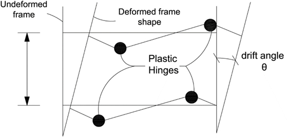
Figure 1. Ideal location of plastic hinge formation in beams (adapted from Sarno and Elnashai, 2002) reproduced with permission from the copyright holder.
Post-Northridge research (Popov et al., 1998; Sofias et al., 2014) presented the reduced beam section (RBS) as a suitable solution to provide the “weak beam–strong column” mechanism. RBSs utilize radius cuts to the beam flanges causing a section reduction, promoting the weak zone to allow yielding. The concept of RBSs was introduced in the 1980s as an effective means to dissipate energy and accommodate extensive rotations sustained under cyclic loading (Plumier, 1997).
More recently, studies of reduced web sections (RWSs) have been proposed (Tsavdaridis et al., 2014; Tsavdaridis and Papadopoulos, 2016) as a suitable alternative following a similar principle to RBSs, but utilizing openings within the web as opposed to the flanges. As RWSs incorporate perforation, they can be used in conjunction with cellular beams to create a “structural fuse” system. Isolating the first perforation at a distance from the column will create the RWS required for plastic hinge formation. Yang et al. (2009) analyzed a fully fixed RWS in a quasi-static, pseudo-dynamic analysis to determine the feasibility of using such connections. The energy caused by the cyclic loading was dissipated through the Vierendeel mechanism, allowing the formation of four plastic around the web opening to redistribute the load, as well as transferring vertical shear forces (Chung et al., 2001; Tsavdaridis and Papadopoulos, 2016).
Pushover Analysis
The most realistic assessment of a structure exposed to an earthquake is a non-linear time-history analysis. However, as this requires a range of appropriate ground motions as well as extensive computational tools, pushover analyses are being used more frequently to estimate the strength of structures exposed to dynamic loading.
The impact of incorporating RWSs into large-scale frames has yet to be studied widely, and this study undertakes a series of non-linear, static pushover analyses to determine the structural strength and inter-story drifts of such frames. Previously, RBSs have been studied in steel frames in research presented by Kildashti et al. (2012) and Ghassemieh and Kiani (2012), finding RBSs reduced inter-storey drifts in the lower storeys of multi-storey structures, as well as reducing the overall capacity curve of the frames.
Study Model
This study uses the structural software ETABS to analyze three steel MRFs first introduced by Jin and El-Tawil (2004). The 4-, 8- and 16-storey frames presented in this paper have become a benchmark for the validation of pushover analyses (Ghassemieh and Kiani, 2012; Kildashti et al., 2012), which this study will similarly validate against. The three MRFs are designed according to American design code and consequently use American beam and column sections. Sofias et al. (2014) identified insufficiencies in using seismic connection parameters based on research using American sections, noting that similar arrangements with European sections did not behave satisfactorily. In lieu of this, this study proposes a set of similar 4-, 8-, and 16-storey frames with equivalent European sections to identify whether the macroscopic behavior of the MRFs varies significantly.
The RBSs and RWSs are simulated using non-linear hinges at the beam ends, defined by a moment–rotation curve to model the reduction in beam strength caused by the removal of steel at the flange and web, respectively. The RWS modeled in this study is based on research conducted by Tsavdaridis and Papadopoulos (2016), termed “model 1”. The finite element study presents a hysteretic moment-rotation curve for this connection (Figure 2), which this study will model using a bilinear idealization.
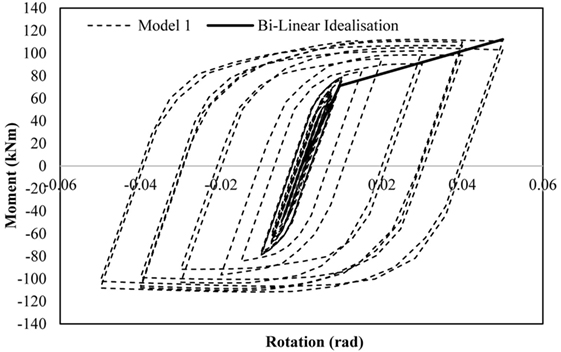
Figure 2. Hysteretic moment-rotation curve for Model 1 (Tsavdaridis and Papadopoulos, 2016).
Validation of Numerical Models
Validation of RWS Model
To ensure that the RWSs used in the 4-, 8-, and 16-storey frames can adequately represent the results attained for Model 1 (Figure 2), it is necessary to model and validate the same frame configuration presented in the FEA study in ETABS, to compare the resulting moment–rotation curve against Figure 2. The RWS will be simulated by placing a user-defined hinge at a distance 200 mm from the beam-to-column connection. A summary of the yield and ultimate capacities of the bilinear idealization is provided in Table 1. Panel zones are not modeled as this validation to be consistent with the omission in the large-scale frames studied later.
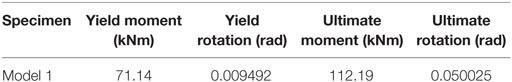
Table 1. Summary of bilinear idealization of moment–rotation curve (Tsavdaridis and Papadopoulos, 2016).
Hinges are typically modeled at locations where plasticity and large non-linear deformations are expected; in this instance, at the position of the RWS. ETABS produces force–displacement graphs to characterize the plasticity that is experienced at a hinge. This function will allow a comparison between the moment–rotation curve of this model and the moment–rotation curve from the FEA study. The configuration of the validation model is shown in Figure 3.
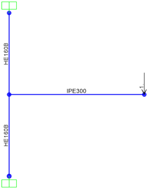
Figure 3. Beam-to-column configuration modeled in ETABS.
A static, non-linear load case is applied to the model, which is displacement controlled to a value of 0.050025 rads—the ultimate rotation of Model 1. The moment–rotation curve results from the ETABS non-linear hinge are compared to the idealized bilinear curve presented by Tsavdaridis and Papadopoulos (2016) in Figure 4.
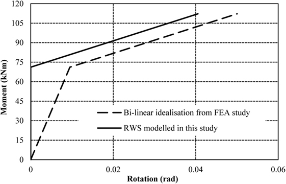
Figure 4. Validation moment–rotation curve comparing results from Tsavdaridis and Papadopoulos (2016) and proposed reduced web section (RWS) model.
The moment–rotation curve representing the RWS from the ETABS model (Figure 4) shows 0 rotation until the yield point is reached; in this case, at a moment of 71.14 kNm. This is a deliberate function of the software, which automatically subtracts the rotation that would occur at the yield point from the subsequential rotation in the plastic region. This causes a constant difference between the results in the plastic region of the bilinear curve (i.e., this difference is the yield rotation). With this comparison, it is clear that the results from the model in this study match with the results presented in the FEA study if we were to manually add the yield rotation (0.009492 rad) subtracted by the software to the RWS modeled in this study. This validation supports the accuracy of using ETABS user-defined hinges to represent the RWS within the 4-, 8-, and 16-storey frames.
4-, 8-, and 16-Storey Frame Configuration
Previous studies of RBSs (Jin and El-Tawil, 2004; Ghassemieh and Kiani, 2012; Kildashti et al., 2012) have used three steel MRFs of varying height; 4-, 8-, and 16-storey. This study will use these frames to validate results against, and then further develop the frames to incorporate RWSs. The RBSs are also modeled using non-linear hinges defined by moment–rotation data from the validation study (Kildashti et al., 2012), which designed the RBSs in accordance to the recommendations proposed by FEMA 350 (2000b).
The frames, initially introduced by Jin and El-Tawil (2004), are designed in accordance with FEMA 302 (1997), FEMA 350 (2000a), and American Institute of Steel Construction, Inc. (2016); the beam and column sizes were selected due to limitations on inter-storey drifts and to promote the “weak beam–strong column” mechanism.
The 4-, 8-, and 16-storey frames are identical in plan consisting of 9.14 m × 9.14 m square bays, totaling a plan area of 36.56 m × 36.56 m. Typical floor-to-floor heights are 3.66 m, except for the first storey, which has a height of 4.57 m. It is assumed that internal members only resist gravity loads; therefore, all lateral loads are resisted by the four external MRFs. As the external frames are identical in orthogonal directions, it is only necessary to assess the lateral loads on one 2D frame. A summary of these configurations is provided in diagrammatic form in Figures 5 and 6.
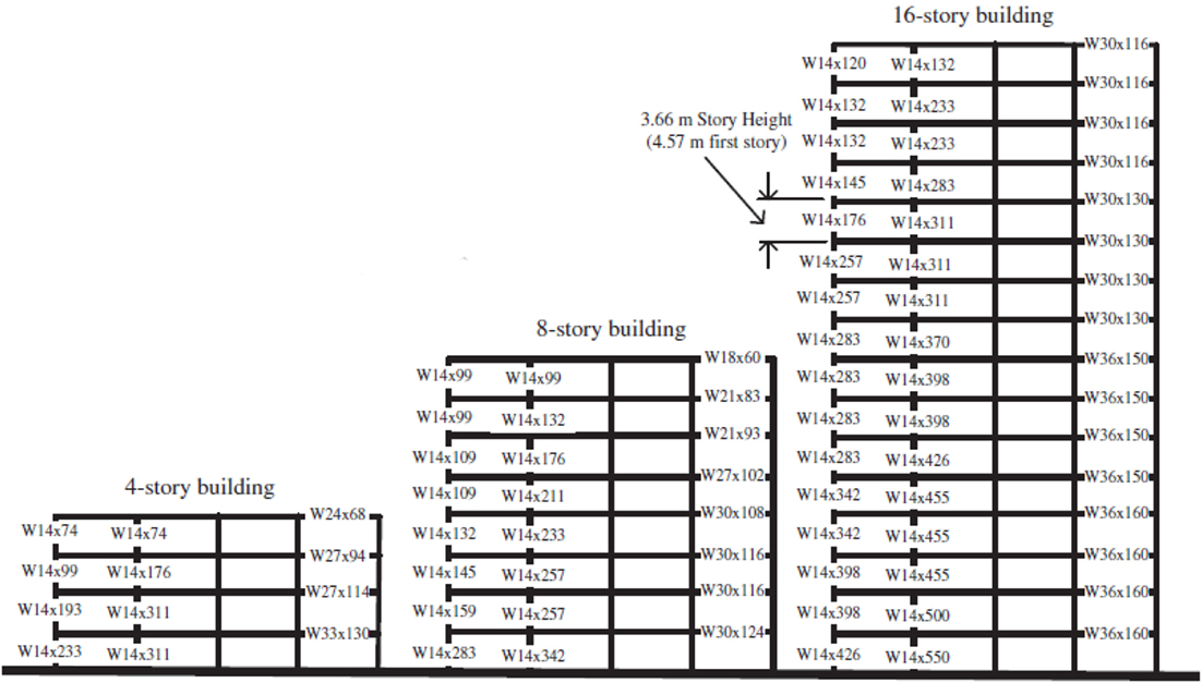
Figure 5. Elevation of 4-, 8-, and 16-storey frames to be used in pushover analyses (Ghassemieh and Kiani, 2012).
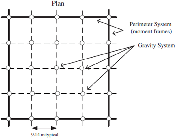
Figure 6. Plan view of 4-, 8-, and 16-storey frame to be used in pushover analyses (Ghassemieh and Kiani, 2012) reproduced with permission from the copyright holder.
The dead and live loads applied to the frames are assumed identical on all floors, but differ for roof level. The roof carries a dead load of 3.64 kN/m2 and a live load of 0.96 kN/m2, while the floors carry 5.55 and 2.39 kN/m2 for dead load and live load, respectively. All beams and columns are A572 grade 50 steel, with a yield strength of approximately 345 MPa. As it is assumed that lateral resistance is provided only by the perimeter SMRF, the frame must be loaded by half of the weight of the structure. The storey mass for the roof and floor levels is calculated as 496 and 757 tonnes, respectively. In combination with this, the full dead load, accompanied with 25% of the live load is included for the pushover analysis (Kildashti et al., 2012).
Pachoumis et al. (2009) established that it is unsuitable to use codes developed for American sections to design European sections, due to the inherent differences in section geometry. To support this, Sofias et al. (2014) further investigated RBSs with European sections to identify the behavior of such connections and establish relationships specific to these sections. Additionally, the RWS used in this study for pushover analyses is based on results from analysis European sections (Tsavdaridis and Papadopoulos, 2016).
To expand on these initial works, this study endeavors to analyze RWSs in a series of pushover analyses using European sections. For validation purposes, the analysis of the 4-, 8-, and 16-storey uses American sections. This study proposes a series of equivalent frames using European sections to analyze the structural performance of RWSs, to lead to the incorporation of RWSs into Eurocode 8. The equivalent sections have been selected based on geometry, cross-sectional area, and moment of inertia. A summary of the sections selected is shown in Tables 2–4. Additionally, grade S355 steel is selected in replacement of A572 grade 50 steel.
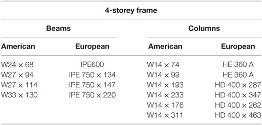
Table 2. Selection of equivalent European sections for 4-storey frame.
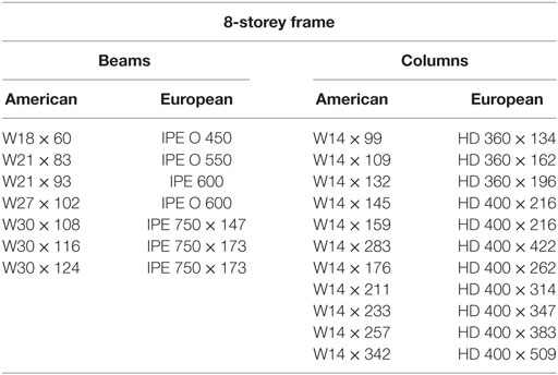
Table 3. Selection of equivalent European sections for 8-storey frame.
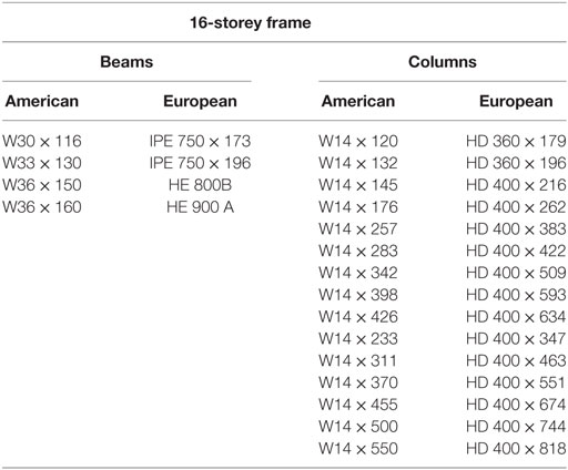
Table 4. Selection of equivalent European sections for 16-storey frame.
Frame Validations
A non-linear, static pushover analysis is undertaken on the three SMRFs using a modal load case. The analysis is based on the first mode of the structures, assumed to be the prominent mode. Typically, pushover analyses of tall frames are not recommended due to the likelihood of higher modes influencing the structure. However, this study will assess the 16-storey frame under the assumption that the first mode remains prominent. In addition, the p-delta “dummy element” method (Jin and El-Tawil, 2004) is omitted to simplify modeling, as the models presented in this study show strong correlation with the preliminary studies until the target displacement.
Due to the inability to predict the forces of an earthquake with precision, there are some inherent difficulties in applying an equivalent static load with sufficient accuracy. Therefore, the most appropriate load control to apply to the frames is through controlled displacement, i.e., the models will be assessed to a target displacement defined at a specific node, typically at the center of the top floor. The target displacement for each model varies due to the differences in frame heights. In alignment with Jin and El-Tawil (2004), the models will be pushed to the maximum anticipated displacement for ground motions with a 2% exceedance probability in 50 years (2 in 50) earthquake (Ibrahimbegovic and Kozar, 2007). This is calculated as 516, 1,128, and 1,631 mm for the 4-, 8-, and 16-storey frames, respectively. The capacity curves from the models in this study are compared to the validation studies (using American sections) in Figures 7–9. The roof displacement is normalized through dividing by the building height, and the base shear is normalized by the weight of the structure.
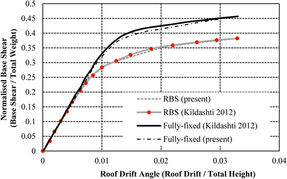
Figure 7. 4-storey frame normalized capacity curve validation.
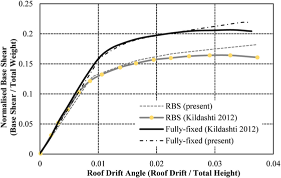
Figure 8. 8-storey frame normalized capacity curve validation.
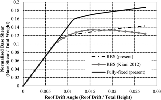
Figure 9. 16-storey frame normalized capacity curve validation.
The results from the models in this study show a strong correlation with the results presented in the initial studies (Jin and El-Tawil, 2004; Ghassemieh and Kiani, 2012; Kildashti et al., 2012). The 4-storey frame is consistent with the validation results throughout both the elastic and plastic performance of the structure. The 8-storey frame shows a small disparity in capacity curves in the plastic region, as the validation study presents the strength degradation of the connections using the Ibarra–Krawinkler method (Jin and El-Tawil, 2004), an aspect omitted from this study for simplification. This provides a small reduction in capacity curve, compared to the constant behavior of the capacity in this study’s model. Similar behavior is noted in the frame with fully fixed and RBSs, as well as the 16-storey RBS frame. As seen in Figures 8 and 9, the deterioration only impacts a small region of the capacity curve and the models are, therefore, deemed suitable for the purposes of this study. It is important to note that neither validation study presents a capacity curve for the 16-storey frame with fully fixed connections. However, this study has included the results attained from this analysis for the purposes of comparing the fully fixed connections with RBSs and RWSs.
To investigate the differences of modeling European sections as opposed to North American sections, equivalent European beams and columns are implemented in the model, which produce the capacity curves in Figures 10–12. The frames exhibit similar behavior comparing the normalized base shear against the roof drift angle. The 4- and 16-storey frames with European sections show a marginal increase in capacity, but the behavior of the frames adequately match the results from the initial validation frames. It is, therefore, concluded that the performance of seismic connections (RBSs) designed in accordance with American code does not differ significantly in performance when using European sections, based on the macroscopic behavior of the frame, despite differences being examined in local connection arrangements in previous studies (Sofias et al., 2014).
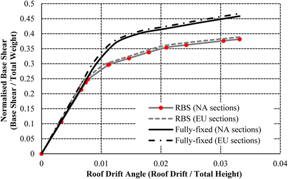
Figure 10. NA vs EU sections normalized capacity curve comparison for 4-storey frame.
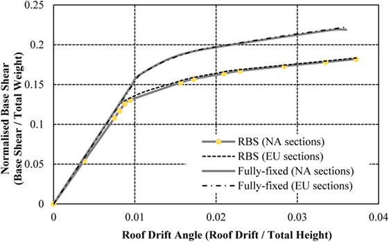
Figure 11. NA vs EU sections normalized capacity curve comparison for 8-storey frame.
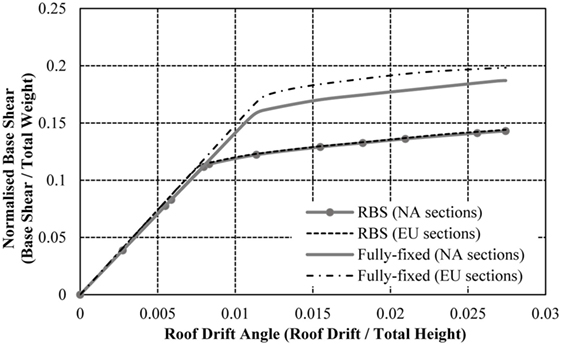
Figure 12. NA vs EU sections normalized capacity curve comparison for 16-storey frame.
Scaling RWS Model
The moment–rotation curve for Model 1 was attained by testing HE160B and IPE300 sections, which are small sections (Tsavdaridis and Papadopoulos, 2016). Consequently, the yield and ultimate moment values attained are small. In comparison, many of the sections used in the benchmark frames are significantly larger and able to achieve larger moment capacities. Therefore, there is an evident lack of compatibility between modeling an RWS with moment–rotation properties based on small sections in a frame with large sections.
In lieu of this, it is necessary to make amendments to the modeling of the RWSs to attain more accurate and informative results. Currently, there have been no studies published that examine the behavior of RWSs with large beams. Therefore, there is a lack of first-hand data available with which to model the RWS. This study proposes analyzing a RWS based on a scaled version of Model 1. The scaling is centered on the comparison of moment–rotation curves attained performing 3-dimensional finite element analysis of a RBS and RWS section with an equivalent reduction of steel volume, i.e., the volume (or mass) removed from the flanges equals the volume removed by the web perforation.
To simplify the model, semi-rigid connections are analyzed under a single linear and non-linear loading cycle, as opposed to completing the number of cycles recommended by the SAC 1997 loading protocol. The RBS arrangement used to scale the RWS is validated from the study presented by Sofias et al. (2014).
The models of the study conducted by the authors are built using the modeling and massing tools of REVIT and the analyses are performed through ANSYS Parametric Design Language (APDL). The section parameters and material mechanical properties replicate those used in the validation study (Sofias et al., 2014) and are presented in Tables 5 and 6. Additionally, as in the Sofias et al. (2014), web plates and continuity stiffeners are introduced to strengthen the panel zone.
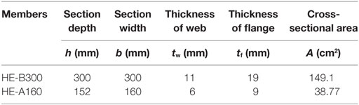
Table 5. Section properties used in FEA.
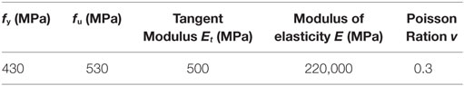
Table 6. Material properties used in FEA.
The FEA takes into account the kinematic rate independent hardening along with the Bauschinger effect to account for the reduction in the yield stress when the dissipative element is reversely loaded. To avoid shear locking and over prediction of stiffness that could consequently underestimate the deformation magnitude in the model. The FEA is compared to the experimental data produced by Sofias et al. (2014) in Figure 13. The results obtained by the authors in this study are presented in Figure 14.
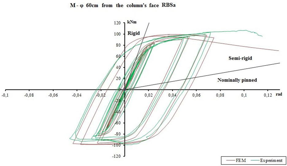
Figure 13. Hysteretic moment–rotation curves from validation study (Sofias et al., 2014) reproduced with permission from the copyright holder.
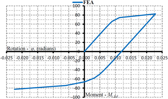
Figure 14. Moment–rotation for reduced beam section in this FEA study.
With reference to Figure 13, the moment that is selected from the first cycle of the experimental specimen curve is 65 kNm with a corresponding rotation of 0.011 rad. Comparatively, the deformation corresponding to this study’s specimen (Figure 14) at a moment of 65 kNm is 0.009 rad. The correlation between these results is satisfactory for the purpose of this scaling.
The model is further developed to analyze the aforementioned RWS with an equivalent volume subtracted from the web exhibits similar behavior to the equivalent RBS (Figure 15), yet, has a higher yield moment of 79.87 kNm compared to 69.89 kNm. Both sections reach the same ultimate moment capacity of 99.84 kNm, at different rotations of 0.1159 and 0.1269 rads for the RBS and RWS, respectively.
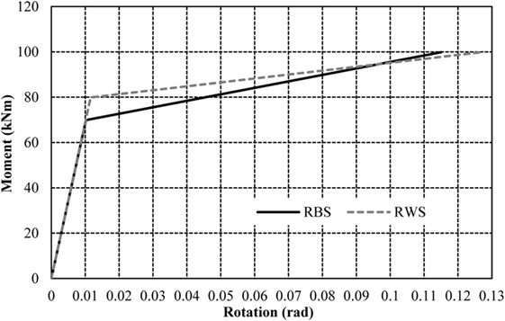
Figure 15. Comparison of bilinear moment–rotation curves for reduced web section (RWS) and reduced beam section (RBS) with equivalent volume reduction from FEA analysis.
In alignment with Tsavdaridis and Papadopoulos (2016), the RBSs and RWSs analyzed in this FEA study are based on smaller sections, resulting in small moment capacities. Therefore, this study will use the relationship established in Figure 15 to formulate scale factors that will be applied to the RBS presented in the initial validation studies (Ghassemieh and Kiani, 2012; Kildashti et al., 2012) to represent the performance of the RWS. The scale factors calculated for this relationship are based on the ratios between yield and ultimate moments and rotations, presented in Table 7. Due to a lack of knowledge regarding the behavior of RWSs and appropriate scaling methodologies, this method is a necessary simplification to proceed with this study. The method is deemed suitable as it is likely the accuracy of small elements will be less significant in the analysis of large frames.
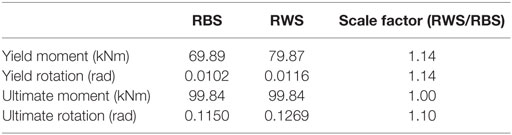
Table 7. Summary of scale factors in reduced beam section (RBS) and reduced web section (RWS) relationship.
Analysis of RWS Frames
4-Storey RWS Frame
The analysis of the RWS frames uses the same gravity loads previously specified, using the same methodology for model analyses used in the validation frames. The resulting normalized base shear vs displacement curve is shown for the 4-storey frame in Figure 16.
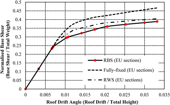
Figure 16. Normalized capacity curves for 4-storey frame with fully fixed connections, reduced web sections (RWSs), and reduced beam sections (RBSs).
As expected, the frame with RWSs has a lower capacity than the fully fixed connection frame. This is due to the loss of strength and stiffness as a result of the perforations at all beam-to-column connections. It is evident that the incorporation of RWSs and RBSs reduces the strength of the structure, as the frames reach a higher displacement with a smaller base shear. The RWS frame reaches the target displacement at a normalized base shear of 0.4, compared with the fully fixed frame, which reaches the displacement at 0.47. The RWS frame retains a higher capacity than the frame with RBSs, with the structure maintaining its elastic state until a large displacement (yielding at 0.0077 compared to 0.0066). The RWS frame exhibits a reduction in base shear of approximately 17%, compared to the reduction of 24% in the RBS frame, in relation to the fully fixed frame.
Figure 17 compares the inter-storey drift ratios for the frames. The fully fixed connections display a more constant inter-storey drift ratio throughout the first three storeys of the frame. The RWS and RBS frames perform similarly, developing smaller drifts in the first storey, but higher drifts in the upper storeys of the frame. The increase in drifts throughout the height of the frames with seismic connections is small, demonstrating that the implementation of such reduced sections in low-rise frames does not drastically affect the lateral movement of the frame.
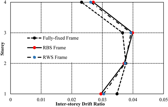
Figure 17. Inter-storey drifts for 4-storey frame.
The comparable behavior of inter-storey drifts between the fully fixed and RWS frames is supported by the sequence in which plastic hinges form (Figures 18 and 19). The color scale denotes the damage experienced at the hinge with the red dot representing failure of the hinge, as well as previous stages of damage including immediate occupancy, life safety, collapse prevention.

Figure 18. Plastic hinge formation in fully fixed 4-storey frame (for cross sections, see Figure 5 and Table 2).

Figure 19. Plastic hinge formation in reduced web section 4-storey frame (for cross sections, see Figure 5 and Table 2).
As the frame is designed in accordance with requirements to develop the “weak beam–strong column” mechanism, the plasticity is generally limited to the beams in the fully fixed frame, with some plasticity forming in the fourth storey columns. The hinges develop in a similar manner in the RWS frame, supporting that RWSs encourage the formation of the desired weak beam mechanism. The RWS frame develops two plastic hinges in the beams in the top storey of the frame, differing from the fully fixed connections, due to the reduction in yield moments at these zones caused by the web perforation. The RWS behavior exhibits increased ability to distribute plasticity throughout all storeys of the frame.
8-Storey RWS Frame
Implementing RWSs in the 8-storey frame develops a similar pattern to the structural behavior pattern of the 4-storey frame, noting a 16% reduction in base shear from 0.22 to 0.19 when compared to fully fixed connections (Figure 20). Comparatively, the frame with RBSs experiences a loss of 22% with a base shear of 0.18. It is established that both types of seismic connections exhibit a similar strength loss as experience in the 4-storey frame, promoting the use of such connections in mid-rise frames without severe impact on the structures stiffness and strength.
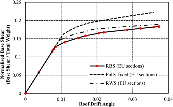
Figure 20. Normalized capacity curve for 8-storey frame with fully fixed connections, reduced web sections (RWSs), and reduced beam sections (RBSs).
The inter-storey drifts (Figure 21) the fully fixed frame experiences are larger than the seismic connection frames until the fourth storey, after which they become lower. The frame with RBSs produces the smallest drifts in the lower storeys, combined with the highest drifts in the upper storeys, contrarily to the frame with RWSs, which is characterized by a smoother curve. RWSs provide the most consistent drifts throughout the height of the frame out of all connections. This behavior is desirable to reduce local damage, often to non-structural components caused by large inter-storey drifts.
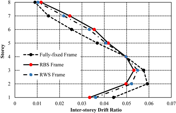
Figure 21. Inter-storey drifts in 8-storey frame.
Comparison of the formation of plastic hinges (Figures 22 and 23) highlights additional plastic hinges forming in the upper storeys of the frame in the RWS frame, compared to the fully fixed frame. This behavior is similar to the hinge sequence in the 4-storey frame, again showing the capacity of RWSs to promote the formation of plasticity in the beam sections throughout the height of the structure, as opposed to concentrating plasticity in the lower storeys. The use of RWSs also prevents the formation of plastic hinges in the upper-storey columns, as experienced in the frame with fully fixed connections. Plasticity within the columns promotes “soft storey” collapse, a mechanism that is particularly problematic in taller frames as the p-delta effect becomes more important (Dhadve et al., 2015).

Figure 22. Plastic hinge formation in 8-storey fully fixed frame (for cross sections, see Figure 5 and Table 3).

Figure 23. Plastic hinge formation in 8-storey reduced web section frame (for cross sections, see Figure 5 and Table 3).
16-Storey RWS Frame
The 16-storey storey frame with RWSs attains a higher capacity than the frame with RBSs, a pattern consistent throughout the analysis of the frames (Figure 24). Compared to the frame with fully fixed connection, the strength reduction in the RWS and RBS frames is 33 and 43%, respectively, which is significantly higher than the strength loss occurring in the 4- and 8-storey frames. As such, the impact of introducing seismic connections into the 16-storey frame is more severe than the 4- and 8-storey frames.
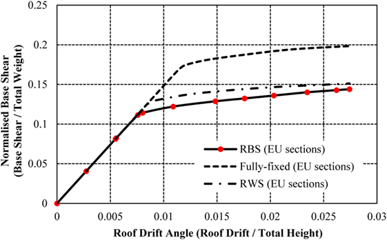
Figure 24. Normalized capacity curve for 16-storey frame with fully fixed connections, reduced web sections (RWSs), and reduced beam sections (RBSs).
The frames with seismic connections experience lower drifts in the first two storeys of the frame (Figure 25), consistent with the results presented in the low-rise and mid-rise frames. The drifts in the seismic connection frames exceed the fully fixed frames in the mid-storeys, but provide smaller and more consistent drifts in the upper-storeys. Comparatively, the fully fixed frame presents inconsistencies between the 8th and 12th storeys. As opposed to the pattern of reducing inter-storey drifts, the frame experiences an increase in drifts between these storeys. These inconsistencies are prevented using both RWSs and RBSs, characterized by smoother curves and more consistent drifts. The pattern of the fully fixed inter-storey drift curve can be better understood with reference to the hinge formation mechanisms (Figures 26 and 27).
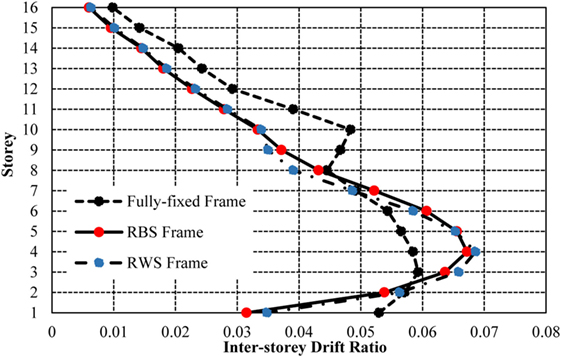
Figure 25. 16-storey frame inter-storey drifts.

Figure 26. Plastic hinge formation in 16-storey fully fixed frame (for cross sections, see Figure 5 and Table 4).

Figure 27. Plastic hinge formation in 16-storey frame with reduced web sections (for cross sections, see Figure 5 and Table 4).
The hinge formation (Figures 26 and 27) pattern in the 16-storey frame aligns with the behavior analyzed in the 4- and 8-storey frames. The 16-storey frame, designed to encourage the “weak beam–strong column” mechanism promotes plasticity in the lower to mid storeys of the frame. Comparatively, the RWS frame develops hinges in a similar sequence, but allows plasticity to form in an extra storey of the structure. This larger distribution of plasticity aids the reduction of drifts in the mid-storeys and allows the consistent drifts between the 8th and 12th storeys, which were not experienced in the fully fixed frames. It is notable that the fully fixed frame develops a critical hinge in the perimeter base column, which may lead to frame instability. The distribution of plasticity through the RWSs prevents extensive hinges from developing in concentrated areas, and as such, a progressive reduction of lateral stiffness was not exhibited.
Conclusion and Limitations
This study assessed the impact of incorporating RWSs into various sized steel MRFs when compared with frames using fully fixed connections and RBSs. The study analyzed the capacity curves, inter-storey drifts, and the plastic hinge formation mechanisms using a series of pushover analyses in ETABS. The RBS and fully fixed frames were validated against benchmark studies (Jin and El-Tawil, 2004; Ghassemieh and Kiani, 2012; Kildashti et al., 2012) to confirm the accuracy of the models used in this study. The RWSs were modeled using non-linear hinges defined by the moment–rotation curve in the results of a comprehensive finite element analysis study (Tsavdaridis and Papadopoulos, 2016). The present study used a simplified scaling assumption to increase the moment capacities of the sections to be compatible with the larger beams and columns used in the frames. The scaling values were attained through a finite element analysis comparison of a RWS and RBS with equal volume of steel removed.
The following notable conclusions have been drawn from this study:
1. The 4-, 8-, and 16-storey frames all exhibit a loss of strength and stiffness with the incorporation of RWSs. The loss of strength is most significant in the 16-storey frame (33%), whereas the loss of strength in the 4- and 8-storey frame (17 and 16%) is less substantial, when comparing RWS frame capacity curves with fully fixed frames.
2. The 4- and 8-storey frames with RWSs exhibit smaller drifts in the lower storeys, but larger drifts in the upper storeys than the fully fixed frames. Contrarily, the 16-storey frame with RWSs presents larger and less consistent drifts in the lower-storeys (peak difference of 0.07 compared to 0.06) and smaller drifts in the upper-storeys (0.007–0.01). In general, for low-rise frames, it is concluded that RWSs provide more consistent drifts in relations to adjacent storeys than fully fixed connections.
3. The incorporation of RWSs encourages the “weak beam–strong column” mechanism to form, enabling plasticity to concentrate within beams. Compared to fully fixed connections, the RWSs also enable plasticity to develop in more storeys throughout the 4-, 8-, and 16-storey frames.
This study concludes that RWSs are suitable for implementation in low to mid-rise frames (4 and 8 storeys), without drastically compromising the strength and stiffness of steel frames. It is necessary to conduct more rigorous research on tall frames with seismic connections, to further understand the impact on structural behavior. However, the initial investigation in this study shows that RWSs are not suitable for taller frames. In addition to this, the results support RWSs as a suitable alternative to the well-established RBS due to their comparable performance in the pushover analyses in this study.
To further develop the understanding of RWSs, the authors recommend the following improvements for future research:
1. The sections selected in this study for the European frame are based on the geometric properties of equivalent American sections. Though these sections have been designed in accordance with American design codes, they do not necessarily adhere to Eurocode 8 (CEN EN., 2004). It is, therefore, recommended that the frames are designed in accordance with EC8, so the behavior of RWSs can be examined in more appropriate frames.
2. Further develop the scaling method used in this study to determine the accuracy. In addition, is it recommended that further section types and sizes are tested, including sections of various classes.
3. Design equations should be established for the implementation of RWSs, to allow specific RWS parameters that vary depending on section sizes to characterize the moment–rotation behavior, as opposed to the scaled RWS properties this study presents.
4. Assessment of RWSs in a series of frames that differ in structural layout, encompassing a range of wide and narrow structures.
5. Analyze the differences in behavior of RWS frames when such sections are only implemented in the lower storeys and the connections in the upper storeys remain fully fixed.
6. Model strength degradation of RWSs with the Ibarra–Krawinkler deterioration model (Ibarra et al., 2005) to characterize the loss of strength after extensive plasticity.
Author Contributions
All authors have been equally contributed for the conduction of this paper. This work is based on DTN’s thesis as supervised by KDT, which is based on previous thesis from AN also supervised by KDT. The report has been proposed with the support of CM.
Conflict of Interest Statement
The authors declare that the research was conducted in the absence of any commercial or financial relationships that could be construed as a potential conflict of interest.
References
American Institute of Steel Construction, Inc. (2016). Seismic Provisions for Structural Steel Buildings, ANSI/AISC Standard 341-16. Chicago, IL: AISC.
Brunesi, E., Nascimbene, R., and Rassati, G. A. (2015). Seismic response of MRFs with partially-restrained bolted beam-to-column connections through FE analyses. J. Constr. Steel Res. 107, 37–49. doi: 10.1016/j.jcsr.2014.12.022
CEN EN. (2004). 1998-1 Eurocode 8: Design of Structures for Earthquake Resistance-Part 1: General Rules, Seismic Actions and Rules for Buildings. Brussels: European Committee for Standardization.
Chung, K. F., Liu, T. C. H., and HKo, A. C. G. (2001). Investigation on Vierendeel mechanism in steel beams with circular openings. J. Constr. Steel Res. 57, 467–490. doi:10.1016/S0143-974X(00)00035-3
Dhadve, P., Rao, A., Rupanvar, A., Deokate, K., Admile, P., and Nemade, P. (2015). Assessment of P-delta effect on high rise buildings. Int. J. Recent Innov. Trends Comput. Commun. 3, 3235.
FEMA 302. (1997). “Part 1 Provisions – NEHRP Recommended Provisions for Seismic Regulations for New Buildings and Other Structures,” in Building Seismic Safety Council-BSSC, (Washington, DC: The Federal Emergency Management Agency).
FEMA 350. (2000a). “Recommended seismic design criteria for new steel moment-frame buildings,” in Connection Qualification, Prepared for the SAC Joint Venture, Chap. 3 (Washington, DC: The Federal Emergency Management Agency, American Society of Civil Engineers-ASCE).
FEMA 350. (2000b). Recommended Seismic Design Criteria for New Steel Moment-Frame Buildings. Washington, DC: The Federal Emergency Management Agency, American Society of Civil Engineers-ASCE.
Ghassemieh, M., and Kiani, J. (2012). Seismic evaluation of reduced beam section frames considering connection flexibility. Struct. Des. Tall Spec. Build. 22, 1248–1269. doi:10.1002/tal.1003
Gioncu, V., and Mazzolani, F. (2013). Seismic Design of Steel Structures. Boca Raton, FL: CRC Press.
Ibarra, L., Medina, R., and Krawinkler, H. (2005). Hysteretic models that incorporate strength and stiffness deterioration. Earthq. Eng. Struct. Dyn. 34, 1489–1511. doi:10.1002/eqe.495
Ibrahimbegovic, A., and Kozar, I. (2007). Extreme Man-Made and Natural Hazards in Dynamics of Structures. Berlin: Springer, 149.
Jin, J., and El-Tawil, S. (2004). Seismic performance of steel frames with reduced beam section connections. J. Constr. Steel Res. 61, 453–471. doi:10.1016/j.jcsr.2004.10.006
Kildashti, K., Mirghaderi, R., and Kani, I. M. (2012). The efficiency of reduced beam section connections for reducing residual drifts in moment resisting frames. Open J. Civil Eng. 2, 68–76. doi:10.4236/ojce.2012.22011
Mahin, S. (1998). Lessons from Damage to Steel Buildings During the Northridge Earthquake. Eng. Struct. 20, 261–270.
Pachoumis, D. T., Galoussis, E. G., Kalfas, C. N., and Christitas, A. D. (2009). Reduced beam section moment connections subjected to cyclic loading: experimental analysis and FEM simulation. Eng. Struct. 31, 216–223. doi:10.1016/j.engstruct.2008.08.007
Popov, E. P., Yang, T. S., and Chang, S. P. (1998). Design of steel MRF connections before and after 1994 Northridge earthquake. Eng. Struct. 20, 1030–1038. doi:10.1016/S0141-0296(97)00200-9
Sarno, L., and Elnashai, A. (2002). Seismic Retrofitting of Steel and Composite Building Structures. Champaign, IL: Mid-America Earthquake Center, Department of Civil and Environmental Engineering, University of Illinois at Urbana.
Smolka, A., and Rauch, E. (1996). The Earthquakes of Northridge 1994 and Kobe 1995 – Lessons for Risk Assessment and Loss Prevention with Special Reference to Earthquake Insurance. Acapulco, Mexico: Elsevier Science Ltd.
Sofias, C. E., Kalfas, C. N., and Pachoumis, D. T. (2014). Experimental and FEM analysis of reduced beam section endplate connections under cyclic loading. Eng. Struct. 59, 320–329. doi:10.1016/j.engstruct.2013.11.010
Tsavdaridis, K. D., Faghih, F., and Nikitas, N. (2014). Assessment of perforated steel beam-to-column connections subjected to cyclic loading. J. Earthq. Eng. 18, 1302–1325. doi:10.1080/13632469.2014.935834
Tsavdaridis, K. D., and Papadopoulos, T. (2016). A FE parametric study of RWS beam-to-column bolted connections with cellular beams. J. Constr. Steel Res. 116, 92–113. doi:10.1016/j.jcsr.2015.08.046
Keywords: beam–column connections, reduced beam section connections, reduced web section connections, seismic-resistant frames, non-linear analysis, plastic analysis, inter-storey drifts, eurocode 8
Citation: Naughton DT, Tsavdaridis KD, Maraveas C and Nicolaou A (2017) Pushover Analysis of Steel Seismic Resistant Frames with Reduced Web Section and Reduced Beam Section Connections. Front. Built Environ. 3:59. doi: 10.3389/fbuil.2017.00059
Received: 27 June 2017; Accepted: 19 September 2017;
Published: 06 October 2017
Edited by:
Luigi Di Sarno, University of Sannio, ItalyReviewed by:
Roberto Nascimbene, European Centre for Training and Research in Earthquake Engineering, ItalyJosé Miguel Castro, Faculdade de Engenharia da Universidade do Porto, Portugal
Christian Málaga-Chuquitaype, Imperial College London, United Kingdom
Copyright: © 2017 Naughton, Tsavdaridis, Maraveas and Nicolaou. This is an open-access article distributed under the terms of the Creative Commons Attribution License (CC BY). The use, distribution or reproduction in other forums is permitted, provided the original author(s) or licensor are credited and that the original publication in this journal is cited, in accordance with accepted academic practice. No use, distribution or reproduction is permitted which does not comply with these terms.
*Correspondence: Chrysanthos Maraveas, c.maraveas@maraveas.gr