The Influence of Overhead Cranes in the Seismic Performance of Industrial Buildings
 Andrea Belleri
 Simone Labò
 Alessandra Marini
 Paolo Riva
- Department of Engineering and Applied Sciences, University of Bergamo, Dalmine, Italy
This paper investigates the influence of overhead cranes with a hanging mass under earthquake type loading, considering the Emilia 2012 seismic sequence. The structural layout of precast concrete industrial buildings typical of the Italian territory is considered. The equations of motion describing the behavior of the hoist load are derived, and a sensitivity analysis is carried out on simplified 3 degrees of freedom systems by solving the governing differential equations. The influence of various parameters on the roof displacement and on the horizontal load transferred by the hanging mass is addressed. The considered parameters are the relative damping of the hanging mass, the length of the hoist ropes, the earthquake record, the hysteretic type of the plastic hinges at the column base, and the behavior factor of the structural system. The results show that for a horizontal component of the considered seismic sequence the structural displacements are amplified in the case of a behavior factor greater than 2.5. A simplified modeling strategy considering small displacements is also investigated. Such model is suitable for response-spectrum analyses. Finally, a three-dimensional case study is analyzed by means of non-linear time history analyses. The results show the influence of the overhead crane on the local performance of some structural and non-structural elements, such as columns and cladding panels, especially when the assumption of rigid roof diaphragm does not apply.
Introduction
The seismic sequence that hit Northern Italy in 2012, particularly the Emilia-Romagna region, caused extensive damage to the built environment (Belleri et al., 2015a, 2015b; Bournas et al., 2014; Magliulo et al., 2014a; Minghini et al., 2016). The region is characterized by wide industrial districts, with several precast concrete buildings mainly built before the enforcement of modern anti-seismic regulations and before the latest classification of the site seismicity of the Italian territory. The structural layout of the considered industrial buildings is made of precast concrete cantilever columns fixed at the base by means of cup footings or other types of mechanical connections (Belleri and Riva, 2012; Haber et al., 2014; Ameli et al., 2016; Dal Lago et al., 2016). The column top ends are hinged to prestressed precast beams by means of dowel connections (Psycharis and Mouzakis, 2012; Magliulo et al., 2014b; Zoubek et al., 2015). In the case of older buildings, the beams are just placed inside reinforced concrete (RC) forks at the top of the columns without any mechanical connection, therefore relying on friction for horizontal load transfer. The roof is made of prestressed precast elements, which may have a TT or an open winged section. The roof elements most of the times simply rest on the main beams without additional connections. The cladding system generally consists of external precast panels (Biondini et al., 2013; Magliulo et al., 2015; Belleri et al., 2016) or by masonry infills. The former type is considered herein. The lateral force resisting system is therefore provided by cantilever columns. The considered buildings were typically designed for sustaining horizontal wind loads or loads induced by overhead cranes, but not for transferring seismic actions. In addition, the friction connections between structural elements could compromise the stability of the system, as observed in post-earthquake damage recognitions and in the following analyses (Belleri et al., 2015a; Casotto et al., 2015; Babič and Dolšek, 2016; Ercolino et al., 2016).
Because the buildings under investigation are industrial buildings, overhead cranes are typically present with runway beams spanning in the longitudinal direction (Figure 1). The loads transferred by the crane to the building structure during operational conditions are available in international standards (such as CEN, 2006), national organizations (such as the Canadian Institute of Steel Construction, 2005) or in proprietary manuals [such as Weaver (1985), among others]. The horizontal loads typically considered are those caused by the acceleration or deceleration of the crane in relation to its movement along the runway beam, by the acceleration or deceleration of the crab in relation to its movement along the crane bridge, by the skewing of the crane in relation to its movement along the runway beam, or by the collision with the buffers. It is interesting to note that the horizontal forces at the wheel contact surface should be taken at least 10% of the maximum vertical wheel load (EN 1991-3, clause 2.5.2.2.3). This value is taken as reference herein.
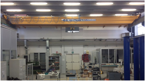
Figure 1. Example of overhead crane in precast concrete buildings.
The seismic load arising from the oscillations of the hoist load is usually neglected, where the term hoist load refers to the sum of the payload and of the lifting attachment. Some authors (Canadian Institute of Steel Construction, 2005; Richard et al., 2009) recognize that in the case of seismic activity, the mass of the crane will interact with the mass of the supporting structure, but they do not refer to the influence of the hoist load. In particular, Richard et al. (2009) analyzed the seismic performance of a typical mill type building made by steel built up members. The authors considered the elastic response in the transverse direction by means of a planar model and focused on the validation of the load estimates obtained from the equivalent static force procedure and the response-spectrum analysis. The suspended load was not modeled. Neglecting the hoist loads in seismic design is likely due to the low response-spectrum accelerations associated with the high fundamental period of vibration of the hoist mass. Indeed, when considering the hoist mass as a pendulum system, the resulting period of vibration is a function of the length of the hoist ropes and it generally lies in the constant displacement region of the pseudo-acceleration spectrum, characterized by low horizontal accelerations.
This paper investigates the influence of the hoist load on the structural response of industrial buildings under earthquake type loading. Typical Italian precast concrete buildings with single portal frames are considered. The equations of motion describing the behavior of the hoist load are derived and a sensitivity analysis is conducted on simplified three degrees of freedom systems by solving the governing differential equations. In this study, only the main shocks of 2012 Emilia seismic sequence are considered. Indeed, the authors specifically intended to address the influence of overhead cranes and hanging loads on the seismic performance of Italian industrial buildings during a seismic sequence that particularly damaged such structural typology. The proposed methodology is suitable for the analysis of the crane and hanging load behavior under other earthquakes, although this generalization is not addressed herein.
The results of the parametric analyses show that the seismic influence of the hoist load is relevant under some conditions, particularly depending on the input ground motion and on the behavior factor of the building. The results of the analyses allow evaluating the horizontal and vertical dynamic amplification factors under seismic conditions. A simplified methodology to account for the hoist load in response-spectrum analyses is also addressed. Finally, a three-dimensional structure is analyzed by means of non-linear time history analyses. The results show the influence of the overhead crane on the local performance of the structural elements, i.e., columns, and non-structural elements, such as cladding panels, especially when the assumption of rigid roof diaphragm does not hold.
Seismic Motion of a Portal Frame with an Overhead Crane
The seismic motion of a building with overhead cranes is studied considering the portal frame depicted in Figure 2A. Beam-to-column hinged connections are considered in accordance with the common features of the investigated industrial buildings. A lumped parameter model with 3 degrees of freedom (3DOF) is assumed (Figure 2B). The ground displacement due to earthquakes is described by its vertical (yg) and horizontal (xg) movements. The chosen degrees of freedom are the roof horizontal displacement (u1) relative to the ground, the vertical displacement of the crane beam (v2) relative to the ground, and the rotation (θ) of the hoist load. The vertical offset between the crane mass and the roof mass is neglected herein, owing to the large height of the columns in the considered buildings. In addition, the position of the hoist mass along the crane might influence the three-dimensional response of the building, particularly by introducing an eccentric load in the direction perpendicular to the crane. In this paper, the hoist mass is considered at the midspan of the crane.
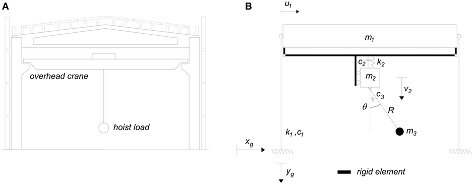
Figure 2. (A) Precast portal frame with overhead crane. (B) Considered simplified 3 degrees of freedom system (3DOF). m1 is the roof mass; k1 and c1 are the lateral stiffness and viscous damping of the columns; m2 is the mass of the overhead crane; k2 and c2 are the vertical stiffness and viscous damping of the crane; m3 and c3 are the mass and viscous damping of the hoist load, respectively; R is the length of the cables.
The free-body diagram of the considered 3DOF system is represented in Figure 3. The horizontal equilibrium of the roof and of the crane (m1 + m2) is
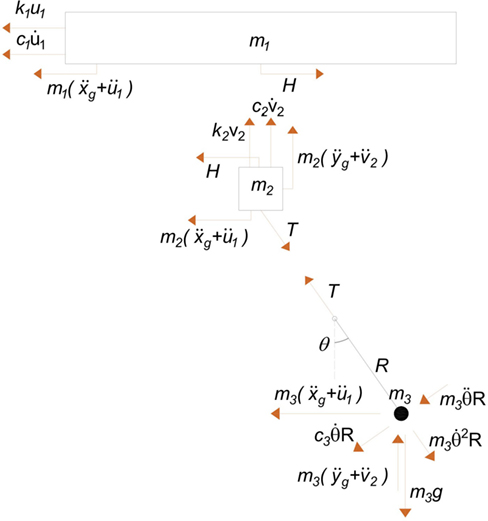
Figure 3. Free-body diagrams of the considered 3 degrees of freedom system. The vertical reactions acting on the crane are transferred directly to the supporting columns.
The vertical equilibrium of the crane beam (m2) is
The rotational equilibrium of the hoist load (m3) around the pivot point is
The hoist load equilibrium along the cables direction is
Substituting T into Eqs 1 and 2, we finally obtain the system of differential equations (Eqs 1–3) governing the motion of the considered 3 DOF system
To account for the inelastic behavior of the columns due to the development of plastic hinges, the elastic lateral load in the columns (k1 u1) is substituted by the inelastic load P(t). The Bouc–Wen hysteresis (Wen, 1976) is considered:
where α is the post-yield stiffness ratio, uy is the lateral displacement at yield, Z is an internal variable whose behavior is described by its derivative:
n, γ, and β are dimensionless quantities. n governs the smoothness of the curve in proximity to the yield point. γ and β control the size and shape of the hysteretic loop (|γ| + |β| = 1). Examples of hysteretic plots according with the Bouc–Wen hysteresis are represented in Figure 4.
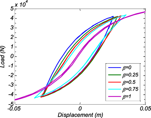
Figure 4. Example of hysteretic plots with the Bouc–Wen hysteresis.
Following the small displacements assumption for the hoist (sin θ = θ, cos θ = 1, and higher order terms equal to 0) and neglecting the vertical displacement of the crane beam, the previous equations of motion (Eq. 5) become:
The system of equations (Eq. 8) looks very similar to the equations of motion governing the classical 2DOF system represented in Figure 5:
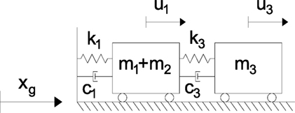
Figure 5. Simplified 2DOF system. u1 is the relative displacement between the roof and the ground; u3 is the relative displacement between the hoist and the roof.
The similarity is obtained from substituting u3 and k3 with θ·R and m3 g/R, respectively. It is observed that the term in Eq. 9 is missing in Eq. 8. This is due to the orientation of the viscous damping vector, which has been taken perpendicular to the hoist cable. Besides this, such difference should not be relevant due to the very low value of the hoist damping. The results of such similarity imply that the dynamic behavior of the hoist load can be accounted for by means of a horizontal spring with stiffness m3 g/R connected to a mass corresponding to the hoist load (i.e., m3). The suitability of this simplified system is presented in the next chapter.
Sensitivity Analysis
A sensitivity analysis is performed to investigate the influence of the various parameters on the system response. Typical Italian industrial buildings consisting of a series of one-storey portal frames (Figure 6) are considered: the columns behave as cantilever beams hinged to double-tapered girders, the roof elements are made by TT beams. The geometry of the buildings (Lb, Li, Hc) is derived from Casotto et al. (2015) and expressed in terms of mean and SD (μ, σ) of a lognormal distribution: (14.90, 0.30 m), (6.80, 0.28 m), and (6.50, 0.25 m) for Lb, Li, and Hc, respectively. Given the geometry of the building, taken as a realization of the aforementioned lognormal distributions, the column cross-section is determined considering the load resulting from a roof dead-load and live-load equal to 2.4 and 2 kN/m2, respectively. It is worth noting that the live-load considered in the static design is the snow load, such load is not accounted for in the seismic mass definition (CEN, 2002). The 2012 Emilia earthquake is selected as the input of the analyses; the main shocks of May 20th and May 29th recorded at Mirandola strong motion station are considered. Such earthquakes are herein referred to as EQ1 and EQ2, respectively. The East-West (E-W), North-South (N-S), and vertical (V) components of each earthquake are included. Table 1 shows the parameters considered in the sensitivity analyses and the related range of interest. Figure 7 shows the elastic response spectra (5% damping) of the considered earthquake components, along with the fundamental period distribution of the considered building realizations and the period of the hoist mass for various cable lengths.
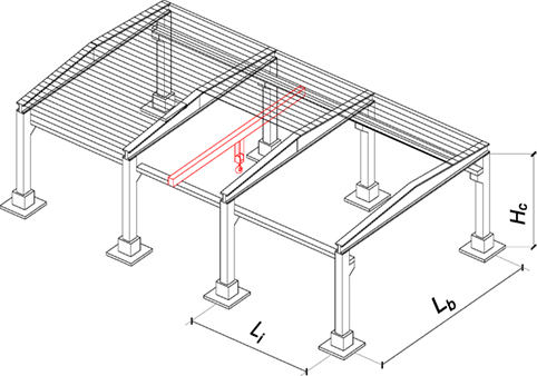
Figure 6. Considered structural typology.
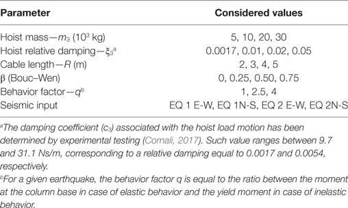
Table 1. Considered parameters and range of interest.
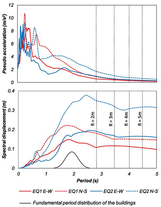
Figure 7. Elastic spectra of the considered earthquake components.
In this paper, the equations of motion (Eq. 5) are solved by means of the “ode45” function (Matlab, 2017). Ode45 is a versatile ordinary differential equation solver and it adopts the Runge–Kutta method with variable time step. The algorithm requires the conversion of the second order differential equations into an equivalent system of first order equations. A generic nth order differential equation with unknown variable y can be converted into a system of n first order differential equations by introducing the following n new variables xi up to the (n − 1) derivative of y: x1 = y, x2 = y(1), x3 = y(2), …, xn −1 = y(n − 2), xn = y(n − 1).
The sensitivity analysis is carried out taking as reference the following parameters: m3 = 30,000 kg, ξ3 = 0.0017, R = 5 m, β = 0.5, and the seismic input EQ1 E-W. All the behavior factors (i.e., 1, 2.5, 4) are considered. The analysis is conducted by changing only one parameter at a time. Figure 8 shows the variation of the median values represented by means of tornado plots. The results are expressed in terms of variation of the roof displacement (Figure 8A) and of the horizontal component of the cable tension (Figure 8B). 1,000 realizations of the building geometry are considered for each set of parameters. In terms of roof displacement, it is observed how the earthquake component is the parameter mostly affecting the results, followed by the length of the hoist cable, for both the elastic (q = 1) and inelastic (q = 2.5 and q = 4) cases. In addition, the higher the behavior factor, the higher the scatter of the results. In terms of cable tension, the earthquake component is the parameter which most affects the results in the elastic case. In the inelastic case, the results are mostly affected by the length of the hoist cable followed by the type of hysteresis (β parameter of the Bouc–Wen model).
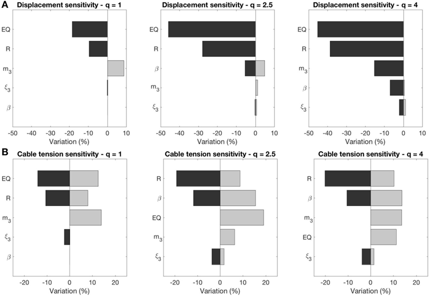
Figure 8. Tornado plots resulting from the sensitivity analysis: (A) displacement sensitivity and (B) sensitivity of the tension in the hoist cable. The displacement and cable tension values for the reference case are 80, 90, and 97 mm (A) and 10.4, 7.5, and 6.7 kN (B), respectively.
Figures 9 and 10 show the influence of the behavior factor and of the seismic input expressed as the cumulative probability of the 1,000 realizations. The aforementioned reference parameters are considered. The results are reported in terms of roof displacement ratio between the cases with and without the hoist load (referred to as “Displacement Ratio” in Figure 9) and in terms of the ratio of the horizontal component of the cable tension between the values obtained from the time history analysis and the values obtained from a response-spectrum analysis (referred to as “Force Ratio” in Figure 10). The values of the response-spectrum analysis are associated with the product of the hoist mass (m3) times the elastic pseudo-acceleration, which is related to the fundamental period of vibration of the pendulum [i.e., 2π√(g/R)] considering 5% relative damping.
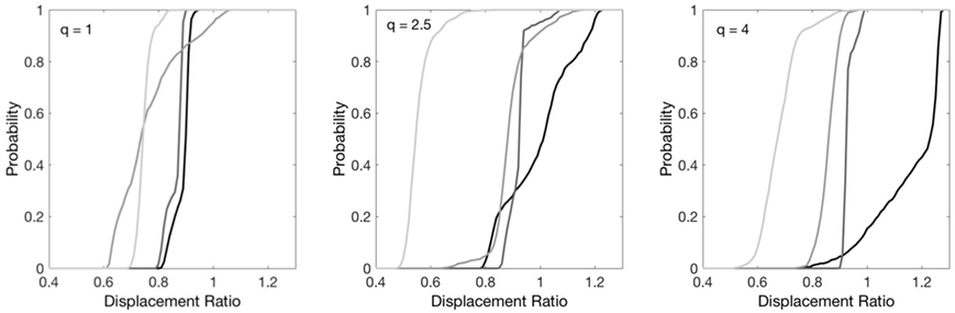
Figure 9. Influence of the behavior factor and of the seismic input on the response of the reference case: roof displacement ratio between the cases with and without the hoist load.
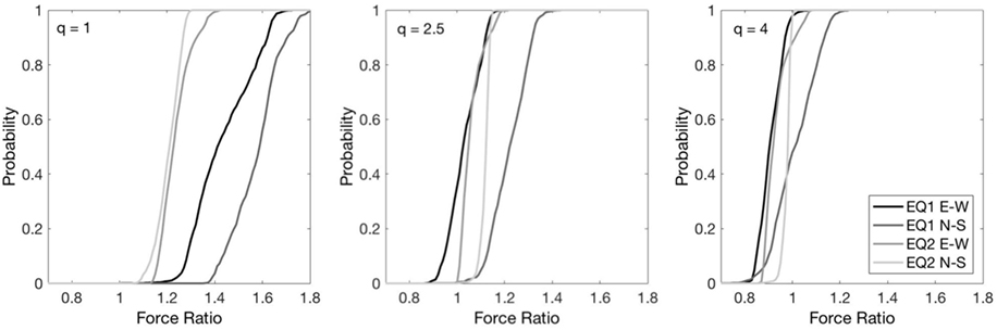
Figure 10. Influence of the behavior factor and of the seismic input on the response of the reference case: ratio of the horizontal component of the cable tension compared to the results obtained from a response-spectrum analysis.
In general, the analysis carried out on the 3DOF model shows that the introduction of the hoist load leads to a reduction of the roof displacement when the columns remain in the elastic range. It is worth mentioning that a pendulum system may act as a tuned mass damper (Gerges and Vickery, 2005), although, for the considered application, the “tuning” is not straightforward because the position of the overhead crane, the mass of the hanging load, the height of the load, and consequently the length of the cables (which determines the period of vibration of the pendulum) are unknown variables during the building operational life. In addition, the tuned mass dampers are generally not effective in reducing peak displacements of the controlled structure after yielding (Pinkaew et al., 2003).
After the development of a plastic hinge at the columns base (i.e., behavior factor greater than 1), the roof displacement associated with the hoist load can be higher than the case without it, depending on the type of input motion. Indeed, one component of the considered seismic sequence (EQ 1 E-W) leads to a median displacement ratio of 1.25 when the behavior factor is equal to 4. As regards the force ratio, the increase of the behavior factor leads to a decrease of such ratio. It is worth mentioning that such a decrease is non-linear and that the median values with q = 2.5 and q = 4 are similar. The high values obtained in the elastic case are related to the relative damping used in the response-spectrum analysis. Indeed, in the response-spectrum analysis, a relative damping of 5% is considered, while the relative damping related to the pendulum motion of the hoist load is lower than 1%. The maximum force ratio among the different earthquake components is about 1.6 in median terms.
Another interesting point arises when evaluating the maximum absolute values of the ratio between the vertical component of the cable tension and the hoist load and between the horizontal component of the cable tension and the hoist load. It is observed that the vertical component of the seismic input affects the vertical component of the cable tension by at most 11 and 23% in the former and latter cases, respectively. The behavior factor does not affect the results. As regards the ratio between the horizontal component of the cable tension and the hoist load, it is worth observing that the maximum recorded value (9%) is less than the minimum ratio (10%) taken for the definition of horizontal forces at the wheel contact surface (EN 1991-3, clause 2.5.2.2.3).
Finally, comparing the results of the simplified 2DOF system (Figure 5) with the results of the elastic 3DOF system, it is observed that higher values, therefore on the safe side, are recorded in the former model for both the roof displacement and the horizontal component of the cable tension. In particular, the maximum median increase of the roof displacement and of the horizontal component of the cable tension is observed considering EQ1 N-S and they are equal to 20 and 22%, respectively. It is worth noting that such values decrease with the increase of the behavior factor (8 and 9%, respectively, for q = 4).
Case Study
Following the results of the previous chapter, the influence of the overhead cranes in a complete structural system is analyzed herein. A case study resembling an Italian industrial building is considered (Figure 11). The building is made by five hinged portal frames whose dimensions, referring to Figure 6, are Lb = 15 m, Li = 8 m, and Hc = 7.2 m. Three rows of RC cladding panels with dimensions 2.4 m × 8.0 m × 0.2 m connect adjacent columns along the longitudinal direction of the building (Figure 11A). Simply supported TT precast elements constitute the roof structural systems. The resulting roof mass per unit surface is 234 kg/m2. An overhead crane with a self-weight equal to 184 kN and a hoist mass (m3) equal to 30,000 kg is considered. The cable length (R) is equal to 5 m.
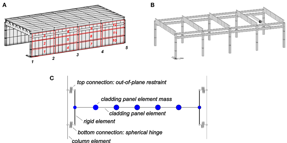
Figure 11. Considered case study: (A) complete model; (B) model without visualizing the roof beams and the cladding panels; and (C) model scheme of the cladding panel.
Non-linear time history analyses are carried out with the software MidasGEN (2012). All the time history analyses are conducted following the Newmark constant acceleration algorithm with an integration time step of 0.01 s. The damping is included in the model following the Rayleigh formulation with tangent stiffness matrix. The Rayleigh coefficients are obtained from considering a relative damping equal to 0.01 and 0.04 associated with the period of vibration of the hanging mass (4.59 s) and the fundamental period of the building without the hoist mass (1.35 s), respectively.
Fiber elements are used to model the columns. The column cross-section (40 cm × 40 cm) is reinforced with eight longitudinal rebars of 14 mm diameter (0.8% longitudinal reinforcement ratio). The concrete cylindrical strength is 50 MPa and the steel yield stress is 450 MPa. The girders and the roof elements are modeled as elastic beams hinged to the supporting structure. The cladding panels are modeled as elastic beams with rigid elements connected to the column (Figure 11C). Top and bottom connections of the cladding panel to the column are different, namely, the bottom connection is a spherical hinge, while the top connection only restrains the out-of-plane displacements. Following the simplified 2DOF model presented in Section “Seismic Motion of a Portal Frame with an Overhead Crane,” the hoist is modeled with the mass m3 connected to the overhead crane by an elastic spring having a stiffness equal to m3g/R. The analyses are carried out considering the Emilia seismic event of May 20th 2012; the N-S and E-W seismic components correspond to the longitudinal and transverse building directions, respectively. The following analyses are considered: a reference case (referred to as R0) without the overhead crane, a case in which the overhead crane is placed by the central column (referred to as R3), the same case R3 with the presence of the hoist payload (referred to as R3-H), a case in which the overhead crane is placed at the midspan of the last bay (referred to as R45), and the same case R45 with the presence of the hoist payload (referred to as R45-H). Two sets of analyses are performed considering in-plane flexible roof (as, for instance, in the case of flexible connections between the roof elements and the supporting beam, Belleri et al., 2014) and in-plane rigid roof. Such analyses are referred to by adding the suffix –F and –R to the previous acronyms, respectively. In all the analyses, the hoist load is placed in the centre of the crane. It is worth mentioning that the position of the hoist mass along the crane might influence the three-dimensional response of the building, particularly by introducing an eccentric load in the direction perpendicular to the crane.
The results of the analyses are expressed in terms of column tip displacement ratio in both directions (Figure 12), i.e., the ratio between the case study with and without the hoist mass. The results show a beneficial effect of the hoist mass in the longitudinal direction, while a negative effect is recorded in the transverse direction for in-plane flexible roofs. Similarly, Figure 13 shows the ratio between the case study with (R3-R, R3-F, R45-R, and R45-F) and without the mass of the crane (R0). The results highlight the importance of including the mass of the crane in the analysis, particularly for eccentric positions and for in-plane flexible roof. Indeed, in the case of in-plane flexible roof, each frame is decoupled in the transverse response, therefore the end frames move less (98 mm) compared to the central frames (156 mm) due to the lower tributary mass of the former. The increase of transverse displacement in the fifth column (R45-F in Figure 13) is a consequence of the overhead crane model which forces the columns in the fourth and fifth alignment to have the same transverse displacement.
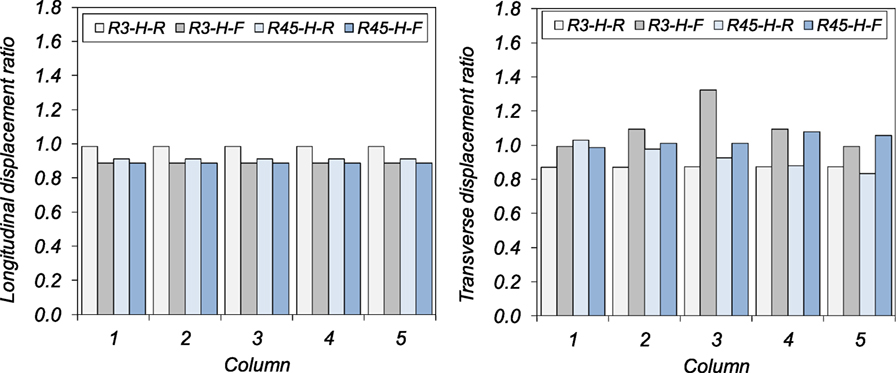
Figure 12. Column tip displacement ratio between the case study with the hoist mass and without it. The column number refers to Figure 11A. The reference R3 values are 195 (234) mm for all the columns in the longitudinal direction for the flexible (rigid) roof, and 106 (145) mm, 151 (145) mm, 140 (145) mm, 151 (145) mm, and 106 (145) mm for each column (1–5) in the transverse direction for the flexible (rigid) roof. The reference R45 values are 172 (294) mm for all the columns in the longitudinal direction for the flexible (rigid) roof, and 105 (171) mm, 162 (134) mm, 162 (98) mm, 83 (72) mm, and 82 (77) mm for each column in the transverse direction for the flexible (rigid) roof.
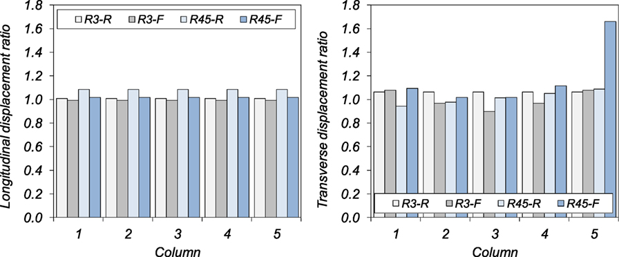
Figure 13. Column tip displacement ratio between the case study with the crane mass and R0. The column number refers to Figure 11A. The R0 reference values are 196 (233) mm for all the columns in the longitudinal direction for the flexible (rigid) roof, and 98 (136) mm, 156 (136) mm, 156 (136) mm, 156 (136) mm, and 98 (136) mm for each column (1–5) in the transverse direction for the flexible (rigid) roof.
To evaluate the suitability of the simplified 3DOF model in predicting the displacement increase in the case of hanging loads, the 3DOF model is applied to the selected building considering configuration R3-R and R3-F in the transverse direction. In the former case, the mass m1 (Figure 2B) is taken as the whole roof mass and the stiffness k1 as the sum of each column stiffness, while in the latter case the mass m1 is taken as the tributary mass of a single bay and the stiffness k1 as the sum of the stiffness of the two columns in the centerline portal frame. The displacement ratios resulting from the simulations are 0.88 and 1.23, for R3-R and R3-F, respectively. Such values should be compared to 0.87 and 1.32 (Figure 12); indeed, an overall good correspondence is observed. It is worth noting that the presence of the rigid floor contributes in distributing the influence of the overhead crane and of the hanging load among all the columns. Such behavior applies also in the longitudinal direction of the considered case study with in-plane flexible roof, due to the presence of just a single bay in the transversal direction.
Torsion on cladding panels is another important aspect to be accounted for (Belleri et al., 2017). Indeed, the differential movements of adjacent columns eventually lead to torsion in the column-to-column cladding panels resulting in additional out-of-plane loads in the connections and in their possible failure. Figure 14 shows the torsion rotation demand in the cladding panels; the cladding panel number refers to Figure 11A. As expected, the torsion rotation demand in the panels is much higher in the case of in-plane flexible roofs compared to in-plane rigid roofs. In general, there is an increase of the maximum panel torsion rotation demand when the mass corresponding to the maximum hoist load is included.
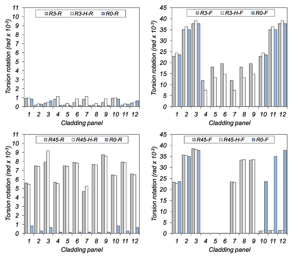
Figure 14. Torsion rotation demand in the cladding panels. The cladding panel number refers to Figure 11A.
In the case of in-plane rigid roof, a significant increase of the panel torsion rotation is recorded when the crane is located in a plan eccentric position. The presence of the hoist load produces an increase of the panel torsion rotation also in the case of in-plane flexible roof, in particular for the central bays, both in the case of a crane located in a plan symmetric and plan eccentric positions. An exception is represented by the panels of the last bay (panels 10, 11, and 12) in correspondence with the overhead crane (case R45-F and R45-H-F); such panels are characterized by a significant decrease of the expected torsion rotation. Finally, it is interesting to note that in the case of flexible roof without the crane (R0-F) the central columns (2–4) move synchronously, therefore only a limited torsion rotation is recorded in the corresponding panels (4–9).
For sake of completeness, the horizontal displacement of the hoist mass is represented in Figure 15 both in absolute terms (i.e., referring to the ground displacement) and in relative terms (i.e., referring to the displacement of the supporting structure). It is interesting to observe that the case studies with in-plane rigid roof are characterized by higher values and more regular movements compared to the case studies with in-plane flexible roof.
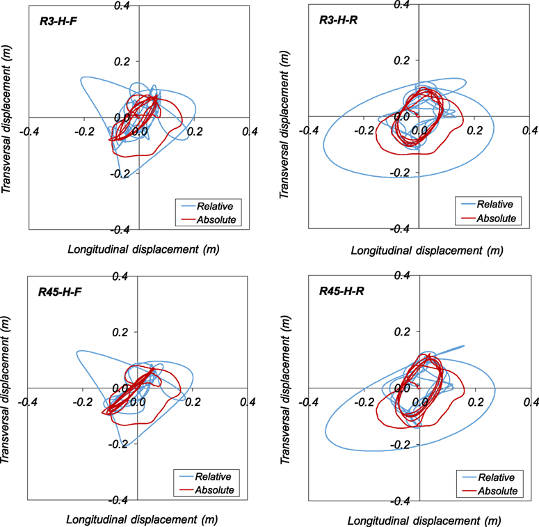
Figure 15. Displacement of the hoist mass in the R3-H-F, R3-H-R, R45-H-F, and R45-H-R cases.
Conclusion
This paper investigated the influence of the overhead cranes and hoist masses in the seismic response of industrial precast concrete buildings. Other authors (Richard et al., 2009) analyzed the seismic influence of the mass of the crane in mill type buildings, but they did not account for to the influence of the hoist load. Herein, a sensitivity analysis was performed considering the structural layout typical of Italian industrial buildings and the main seismic events that hit the Emilia-Romagna region (Italy) in 2012. The equations of motion of a planar three degrees of freedom 3DOF system resembling the considered building typology were solved analytically. The considered 3DOF were the horizontal component of the roof displacement, the vertical component of the overhead crane, and the rotation of the hoist. The results, expressed in terms of cumulative probability and tornado diagrams, showed the negative influence of the hoist mass in some conditions. Indeed, an increase of lateral roof displacements was recorded for one component of the considered ground motions in the case of behavior factor greater than 2.5. Similar behavior factors are typically found in precast industrial buildings not designed for seismic actions.
A simplified modeling procedure was developed to evaluate the influence of the hoist mass in the response-spectrum analyses. The hoist dynamic behavior is modeled by means of a horizontal spring and the hoist mass. The stiffness of the horizontal spring is the stiffness of a pendulum. The procedure developed is therefore suitable for the evaluation of the influence of the hoist mass also in the case of other building typologies and other ground motions.
A complete three-dimensional case study was considered to investigate the influence of eccentric positions of the overhead crane and the influence of roof in-plane flexibility. The hoist dynamic behavior was modeled by means of horizontal elastic springs connecting the hoist mass, one spring for each of the two principal directions. The results showed a beneficial effect of the hoist mass in the longitudinal direction (i.e., along the runway beams direction), while a negative effect was recorded in the transverse direction (i.e., along to the crane direction) for in-plane flexible roofs, in particular because of the increase of torsion displacements induced by the hoist load oscillations. This phenomenon is not present in the longitudinal direction due to the symmetry of the position of the hoist load and to the presence of a single bay.
Finally, another important aspect to be accounted for is the torsion induced on cladding panels, which may result in additional out-of-plane loads in the connections as addressed in the previous research (Belleri et al., 2017). The torsion rotation demand in the panels was much higher in the case of in-plane flexible floors compared to in-plane rigid floors. In general, an increase of the maximum panel rotation demand was recorded when the mass corresponding to the maximum hoist load was included, probably due an increase of asynchronous displacements induced in adjacent columns by the hoist load oscillations.
Author Contributions
AB: defined the problem and addressed the solution step by step, supervised the analyses, wrote the article, and drafted some figures. SL: carried out the sensitivity and finite element analyses, solved the differential equations, and drafted some figures. AM and PR: evaluated the results of the analyses and contributed in the discussion of the results interpretation, revised the various versions of the manuscript and contributed in addressing topics to be investigated in future research.
Conflict of Interest Statement
The authors declare that the research was conducted in the absence of any commercial or financial relationships that could be construed as a potential conflict of interest.
References
Ameli, M. J., Brown, D. N., Parks, J. E., and Pantelides, C. P. (2016). Seismic column-to-footing connections using grouted splice sleeves. ACI Struct. J. 113, 1021–1030. doi: 10.14359/51688755
Babič, A., and Dolšek, M. (2016). Seismic fragility functions of industrial precast building classes. Eng. Struct. 118, 357–370. doi:10.1016/j.engstruct.2016.03.069
Belleri, A., Brunesi, E., Nascimbene, R., Pagani, M., and Riva, P. (2015a). Seismic performance of precast industrial facilities following major earthquakes in the Italian Territory. J. Perform. Constr. Facil. 29, 04014135. doi:10.1061/(ASCE)CF.1943-5509.0000617
Belleri, A., Torquati, M., Riva, P., and Nascimbene, R. (2015b). Vulnerability assessment and retrofit solutions of precast industrial structures. Earthq. Struct. 8, 801–820. doi:10.12989/eas.2015.8.3.801
Belleri, A., Cornali, F., Passoni, C., Marini, A., and Riva, P. (2017). Evaluation of out-of-plane seismic performance of column-to-column precast concrete cladding panels in one-storey industrial buildings. J. Earthq.Eng. Struct. Dyn. doi:10.1002/eqe.2956
Belleri, A., and Riva, P. (2012). Seismic performance and retrofit of precast concrete grouted sleeve connections. PCI J. 57, 97–109. doi:10.15554/pcij.01012012.97.109
Belleri, A., Torquati, M., Marini, A., and Riva, P. (2016). Horizontal cladding panels: in-plane seismic performance in precast concrete buildings. Bull. Earthq. Eng. 14, 1103–1129. doi:10.1007/s10518-015-9861-8
Belleri, A., Torquati, M., and Riva, P. (2014). Seismic performance of ductile connections between precast beams and roof elements. Mag. Conc. Res. 66, 553–562. doi:10.1680/macr.13.00092
Biondini, F., Dal Lago, B., and Toniolo, G. (2013). Role of wall panel connections on the seismic performance of precast structures. Bull. Earthq. Eng. 11, 1061–1081. doi:10.1007/s10518-012-9418-z
Bournas, D. A., Negro, P., and Taucer, F. F. (2014). Performance of industrial buildings during the Emilia earthquakes in Northern Italy and recommendations for their strengthening. Bull. Earthq. Eng. 12, 2383–2404. doi:10.1007/s10518-013-9466-z
Canadian Institute of Steel Construction. (2005). in Crane-Supporting Steel Structures Design Guide, ed. R. A. MacCrimmon (Ontario, Canada: Canadian Institute of Steel Construction).
Casotto, C., Silva, V., Crowley, H., Nascimbene, R., and Pinho, R. (2015). Seismic fragility of Italian RC precast industrial structures. Eng. Struct. 94, 122–136. doi:10.1016/j.engstruct.2015.02.034
CEN. (2002). EN 1990:2002, Eurocode – Basis of Structural Design. Brussels, Belgium: European Committee for Standardization.
CEN. (2006). EN 1991-3:2006, Eurocode 1: Actions on Structures – Part 3: Actions Induced by Cranes and Machinery. Brussels, Belgium: European Committee for Standardization.
Cornali, F. (2017). Evaluation of the Expected Annual Loss for Precast Concrete Industrial Structures. PhD thesis, University of Bergamo, Italy.
Dal Lago, B., Toniolo, G., and Lamperti, M. (2016). Influence of different mechanical column-foundation connection devices on the seismic behaviour of precast structures. Bull. Earthq. Eng. 14, 3485–3508. doi:10.1007/s10518-016-0010-9
Ercolino, M., Magliulo, G., and Manfredi, G. (2016). Failure of a precast RC building due to Emilia-Romagna earthquakes. Eng. Struct. 118, 262–273. doi:10.1016/j.engstruct.2016.03.054
Gerges, R. R., and Vickery, B. J. (2005). Optimum design of pendulum-type tuned mass dampers. Struct. Design Tall Spec. Build. 14, 353–368. doi:10.1002/tal.273
Haber, Z. B., Saiidi, M. S., and Sanders, D. H. (2014). Seismic performance of precast columns with mechanically spliced column-footing connections. ACI Struct. J. 111, 639–650. doi:10.14359/51686624
Magliulo, G., Ercolino, M., and Manfredi, G. (2015). Influence of cladding panels on the first period of one-story precast buildings. Bull. Earthq. Eng. 13, 1531–1555. doi:10.1007/s10518-014-9657-2
Magliulo, G., Ercolino, M., Petrone, C., Coppola, O., and Manfredi, G. (2014a). The Emilia earthquake: seismic performance of precast reinforced concrete buildings. Earthq. Spectra 30, 891–912. doi:10.1193/091012EQS285M
Magliulo, G., Ercolino, M., Cimmino, M., Capozzi, V., and Manfredi, G. (2014b). FEM analysis of the strength of RC beam-to-column dowel connections under monotonic actions. Construct. Build. Mater. 69, 271–284. doi:10.1016/j.conbuildmat.2014.07.036
Minghini, F., Ongaretto, E., Ligabue, V., Savoia, M., and Tullini, N. (2016). Observational failure analysis of precast buildings after the 2012 Emilia earthquakes. Earthq. Struct. 11, 327–346. doi:10.12989/eas.2016.11.2.327
Pinkaew, T., Lukkunaprasit, P., and Chatupote, P. (2003). Seismic effectiveness of tuned mass dampers for damage reduction of structures. Eng. Struct. 25, 39–46. doi:10.1016/S0141-0296(02)00115-3
Psycharis, I. N., and Mouzakis, H. P. (2012). Shear resistance of pinned connections of precast members to monotonic and cyclic loading. Eng. Struct. 41, 413–427. doi:10.1016/j.engstruct.2012.03.051
Richard, J., Tremblay, R., Koboevic, S., and MacCrimmon, R. A. (2009). “Seismic analysis and design approaches for crane-supporting steel structures,” in Proceedings of the Sixth International Conference on Behaviour of Steel Structures in Seismic Areas (Philadelphia, USA).
Weaver, W. M. (1985). Whiting Crane Handbook, 4th Edn. Harvey, Illinois: Whiting Corporation. Third Printing.
Wen, Y. K. (1976). Method for random vibration of hysteretic systems. ASCE J. Eng. Mech. 12, 249–263.
Keywords: overhead crane, hoist load, industrial buildings, floor diaphragm
Citation: Belleri A, Labò S, Marini A and Riva P (2017) The Influence of Overhead Cranes in the Seismic Performance of Industrial Buildings. Front. Built Environ. 3:64. doi: 10.3389/fbuil.2017.00064
Received: 17 July 2017; Accepted: 06 October 2017;
Published: 02 November 2017
Edited by:
Fabio Mazza, University of Calabria, ItalyReviewed by:
Mariella Diaferio, Politecnico di Bari, ItalyAlfredo Camara, City University College, United Kingdom
Crescenzo Petrone, Willis (United Kingdom), United Kingdom
Copyright: © 2017 Belleri, Labò, Marini and Riva. This is an open-access article distributed under the terms of the Creative Commons Attribution License (CC BY). The use, distribution or reproduction in other forums is permitted, provided the original author(s) or licensor are credited and that the original publication in this journal is cited, in accordance with accepted academic practice. No use, distribution or reproduction is permitted which does not comply with these terms.
*Correspondence: Andrea Belleri, andrea.belleri@unibg.it