Framing Failures in Wood-Frame Hip Roofs under Extreme Wind Loads
 Sarah A. Stevenson
 Gregory A. Kopp
 Ayman M. El Ansary
- 1Boundary Layer Wind Tunnel Laboratory, Faculty of Engineering, University of Western Ontario, London, ON, Canada
- 2Department of Civil and Environmental Engineering, University of Western Ontario, London, ON, Canada
Wood-frame residential roof failures are among the most common and expensive types of wind damage. Hip roofs are commonly understood to be more resilient during extreme wind in relation to gable roofs. However, inspection of damage survey data from recent tornadoes has revealed a previously unstudied failure mode in which hip roofs suffer partial failure of the framing structure. In the current study, evidence of partial framing failures and statistics of their occurrence are explored and discussed, while the common roof design and construction practice are reviewed. Two-dimensional finite element models are developed to estimate the element-level load effects on hip roof trusses and stick-frame components. The likelihood of failure in each member is defined based on relative demand-to-capacity ratios. Trussed and stick-frame structures are compared to assess the relative performance of the two types of construction. The present analyses verify the common understanding that toenailed roof-to-wall connections are likely to be the most vulnerable elements in the structure of a wood-frame hip roof. However, the results also indicate that certain framing members and connections display significant vulnerability under the same wind uplift, and the possibility of framing failure is not to be discounted. Furthermore, in the case where the roof-to-wall connection uses hurricane straps, certain framing members and joints become the likely points of failure initiation. The analysis results and damage survey observations are used to expand the understanding of wood-frame residential roof failures, as they relate to the Enhanced Fujita Scale and provide assessment of potential gaps in residential design codes.
Introduction
The resilience of houses during extreme wind events is essential to ensure safety of occupants, minimize damage to internal contents, and lessen the financial burden on communities and insurance providers. Significant work has been completed to date to address commonly observed failure modes in residential structures. These are primarily related to the roof and wall cladding systems and the vertical load path between the structural components (van de Lindt et al., 2013). The majority of housing in North America consists of wood-frame, single-family homes (Amini and van de Lindt, 2014; Standohar-Alfano and van de Lindt, 2016). Residential roof failures, namely failure of roof-to-wall connections (RTWC) and loss of roof sheathing, have been studied extensively due to their high rate of occurrence during extreme wind events. The density of houses relative to other structures in any populated area leads to high costs associated with residential failures. For example, in Oklahoma since 1989, two-thirds of the $32 billion insured losses due to tornadoes are related to residential structures (Simmons et al., 2015).
Work to mitigate failures in wood-framed residential roofs is important because loss of a single sheathing panel, which can occur at relatively low wind speeds, will allow for water ingress. This often leads to loss of the entire contents due to heavy rainfall that accompanies windstorms (Sparks et al., 1994). Observations recorded during post-storm damage surveys have previously led to the identification of important failure trends in various building components. Repetitive failures of similar components suggest that widespread mitigation is possible through improved design approaches and innovative solutions.
The standardized method for assessing wind speeds in tornadoes is the Enhanced Fujita (EF) Scale, which is based on damage observations since it is not generally feasible to measure wind speeds in tornadoes directly (Kopp et al., 2012). The current version of the EF-Scale (Wind Science and Engineering Centre, 2006) provides wind speed estimates for 28 categories of common structures and vegetation, referred as damage indicators (DIs). Under each DI, the EF-Scale utilizes the concept of degrees of damage (DOD). DODs describe the sequential modes of damage that have been typically observed to occur for particular DIs. Each DOD is associated with a minimum, maximum, and expected wind speed. These values represent the range of estimated wind speeds required to cause the specified damage (Wind Science and Engineering Centre, 2006; Mehta, 2013). They can be related back to the EF-Scale wind speeds to estimate the intensity of a tornado, from EF0 to EF5. In the present study, the DI for one- and two-family residences (FR12) is of particular interest. The DODs of FR12 that are relevant to roof failures are DOD-4 and DOD-6, which are described in Table 1. DOD-7, relating to wall collapse, is also included because it occurs within a similar range of wind speeds as DOD-6 and can often occur as a result of roof failure.
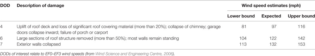
Table 1. Degree of damage (DOD) descriptions and wind speed estimates for failure modes of interest in the one- and two-family residences (FR12) damage indicator.
Figure 1 shows an example of typical sheathing failure, and Figure 2 shows failure of the RTWC. As mentioned, most past research on roof damage focuses on these two failure modes. It is apparent that the wind speed estimates for roof damage in the EF-Scale are heavily based on these well-understood modes. Although DOD-6 encompasses all possible modes of major roof failures, a review of the available literature shows that the current understanding of DOD-6 is limited to research focused on RTWC failures. DOD-6 can occur at an expected wind speed of 122 mph (Table 1). This wind speed corresponds to relatively weak EF2 tornadoes (Wind Science and Engineering Centre, 2006). DOD-4 occurs at lower wind speeds. Gable roofs have been observed to perform poor under these modes, especially DOD-6, compared to neighboring hip roofs of similar construction. In fact, the FR12 listing from the Canadian EF-Scale (Environment Canada, 2013) notes that for hip-roofed homes, the upper-bound wind speeds for DODs 4 and 6 can be assumed. This is contrary to the original EF-Scale documentation (Wind Science and Engineering Centre, 2006), which specifies that the lower bound of DOD-6 is due to inadequate construction or large overhangs while the upper bound is due to enhanced construction such as the use of hurricane straps. The difference between these two versions of the EF-Scale is a significant point, which warrants further investigation, as pointed out by Gavanski and Kopp (2017).
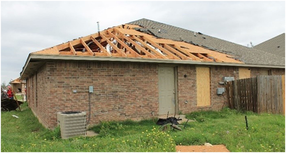
Figure 1. Example of roof sheathing failure, corresponding to DOD-4 (image source: Dr. David Prevatt of University of Florida).
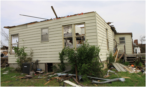
Figure 2. Example of roof-to-wall-connection failure, corresponding to DOD-6 (image source: Dr. David Prevatt).
Residential roofs can be constructed using a range of shapes and slopes. Many include dormers or other discontinuities to cover irregular-shaped houses. Out of the various roof shapes possible in wood-frame construction, the most common in North America are gable and hip roofs, or their composites (Canada Mortgage and Housing Corporation, 2014). Damage surveys following windstorms and subsequent research have frequently identified a disparity in damage between the different geometric forms of residential roofs (Meecham, 1992). Hip roofs are generally known to perform better than other roof shapes. Fragility analyses by Kopp et al. (2016) and Gavanski and Kopp (2017) have even suggested that a single DI for residential structures in the EF-Scale may be inadequate due to significant variations in the estimated failure in wind speeds for different roof shapes, although this has not been quantified in damage surveys.
Several past studies have investigated the superior performance of hip-roofed homes (Meecham et al., 1991; Meecham, 1992), with some more recent works directly investigating hip roof behavior with regard to roof sheathing (DOD-4) and RTWC (DOD-6) performance (Henderson et al., 2013; Kopp et al., 2016). Meecham et al. (1991) performed wind tunnel testing to enhance the technical understanding of hip roof performance and found that there is an important relationship between the pressure distribution and underlying framing configuration in wood-frame roofs. Despite significant differences between the pressure distributions recorded for the gable and hip roof models, the overall roof uplift and overturning moments were found to be quite similar. This verified that preferable aerodynamic geometry is not the only reason for improved performance of hip roofs.
Meecham et al.’s (Meecham et al., 1991) results indicated that the orientation of framing members in a hip roof, relative to the distribution of uplift, provides additional resilience. By contrast, the shape of the gable roof causes higher localized peak pressures and the orientation of framing members results in less-favorable load sharing. In addition to this, hip roofs have RTWCs around their entire perimeters, while gable roofs are only connected to the wall framing along two opposite walls. In combination with improved load sharing within trussed hip roofs, these factors are generally believed to make hip roofs significantly more resistant to damage through the common modes of roof failure. This is also supported by fragility analyses (Kopp et al., 2016; Gavanski and Kopp, 2017).
One of the questions that arises from the high wind speeds obtained in the fragility analyses of particular failure modes is whether other modes become the weak link in hip roofs. In other words, rather than failure of RTWCs, will the structure fail in a different way? The objective of this paper is to examine whether additional, unstudied failure modes are possible and, if they are, to understand the conditions required for them to occur. This paper presents analysis and results of two-dimensional numerical models for trussed and stick-frame hip roofs to examine this point. Analysis of the survey results are also used to support the hypothesis that other failure modes are reasonably common in hip roofs.
Damage Survey Analysis
Data from recent events in the United States have been obtained for examination in the present research. These data were gathered following destructive tornadoes in the Southern US, including the Moore, Oklahoma tornado of 2013 (EF5) and the Tuscaloosa, Alabama (EF4) and Joplin, Missouri (EF5) tornadoes of 2011. They were provided to the authors by Dr. David Prevatt of the University of Florida. Forensic assessment teams of researchers, engineers, and students spent the days following these events surveying the affected areas and documenting observed damage. Their reports on these tornadoes can be found in the literature (Prevatt et al., 2011, 2013; Graettinger et al., 2014). The combined database provides thousands of images of damage to houses, ranging from sheathing loss to total destruction.
The Moore, OK tornado was determined to be an EF5 event, with damage ranging from EF0 to EF5 observed across the path of the tornado. This event killed 24 people and was estimated to have caused up to $3 billion of economic loss (Graettinger et al., 2014). EF0–EF2 winds typically comprise about 85% of the damage area of a strong EF4 or EF5 tornado, and so many stages of damage progression could be identified. The survey performed following this event has informed subsequent research including identification of new methods for improved damage surveys, fragility analyses of house components, and the development of improved laboratory simulations for tornadoes (Graettinger et al., 2014). It also led to changes in the Moore, OK building code such that wood-frame houses have new prescriptive requirements to mitigate up to DOD-6 damage (Ramseyer et al., 2014).
The raw database of photos taken following the Moore, Tuscaloosa, and Joplin tornadoes is used in the present study to examine the nature of hip roof failures. Many instances of partial hip roof failures are identified in the data. As with the findings of the fragility analyses in Kopp et al. (2016), the observed failures evoke additional questions regarding the likelihood and conditions under which partial hip roof failures may occur. Selected examples of the observed failures from Moore are shown in Figure 3 and discussed below.
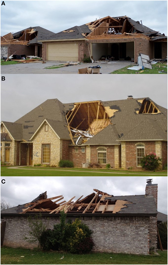
Figure 3. Hip roof failures in Moore, OK following the EF5 tornado of May 21, 2013. (A) Failure of front face of neighboring, stick-frame hip roofs. (B) Failure of front face of stick-frame hip roof, with intact framing of opposite face visible. (C) Framing and sheathing failure in combined hip/gable roof (image source: Dr. David Prevatt).
Figure 3A shows neighboring hip-roofed homes that exhibit similar failures of the front face of the roof. The RTWCs appear to be intact around the remaining perimeter of the roof and it is apparent that several members of the roof frame have failed or been removed, in addition to the sheathing covering this portion. At the right side of the photo, the remaining part of the roof is sagging, which further indicates that the underlying frame has failed. The houses shown in Figure 3A were located along Kyle Drive at the western edge of Moore, OK. Several houses along this short stretch had similar failures of hip roof framing and were built around 2006 (Graettinger et al., 2014). Inspection of the damage photos from this neighborhood indicate that, of houses experiencing DOD-4 or DOD-6 roof damage, 40% appeared to have failed through similar partial failures. In these cases, it appears that the frame failed at the nailed connections between the members, as no broken lumber is visible. The following section will present additional statistics and observations from two selected neighborhoods following the Joplin, MO tornado.
Figure 3B shows a failure similar to that in Figure 3A, but of a much steeper roof. The RTWCs appear to be intact, and a large open cavity is visible where both framing members and sheathing have been removed. Similar to Figure 3A, it is apparent that this roof did not exclusively suffer sheathing loss, although the smaller area of sheathing loss at the right side of the photo should be noted. The lack of visible internal members in the cavity, especially those supporting the intact opposite face of the roof, strongly suggest that this roof was built as a stick-frame structure as opposed to the one containing prefabricated trusses. Many of the failed hip roofs in the available data appear to have used stick framing.
Figure 3C shows a partial failure of a combined hip/gable roof. This failure is unique from those shown in Figures 3A,B because material failure of the wood members is apparent. The RTWCs appear to be intact, with the lower part of the roof having lost only sheathing on the right side and framing members, in addition to sheathing, on the left. Near the peak of the roof, the frame has failed on both faces. This structure appears to contain either trusses or stick framing with robust connections. As indicated in the figure just above the RTWC, the members were connected or otherwise reinforced using nailed wooden plates.
Upon inspection of the failures shown in Figure 3 and similar damage in the available photos, it becomes apparent that partial framing failures are possible, repetitive modes of failure occurring in hip roofs. When comparing these hip roof failures to nearby structures from the data, it was determined that framing failures may govern in some hip roofs at EF2 wind speeds, rather than RTWC failures or sheathing loss. It is also noted that the construction of the roof may be important. The observed stick-frame failures especially suggested that the performance of stick-frame roofs should be distinguished from that of trussed structures in analysis and design, as well as in the present research.
Statistical Analysis of Failure Occurrence
For a complete analysis of the occurrence of partial roof-framing failures, all observed damage within the DOD-4 and DOD-6 ranges must be categorized to identify whether the observed failures are related to the sheathing, RTWCs, or the roof framing. Sorting the data by neighborhood offers additional information about trends across small regions, compared to the entire damage track of an event. As mentioned, the survey data provided by the University of Florida include a database of photos. Also provided is a listing of every photo that was used for assessing the event including the longitude, latitude, and EF-Scale rating at each location. These data were mapped and labeled with color-coded pins to represent the EF-Scale ranking. A sample from the resulting map is shown in Figure 4. This map shows the two areas analyzed to obtain the preliminary statistics presented herein. These neighborhoods were located at the West end of the damage path. Only the data corresponding to EF1, EF2, and EF3 damage are analyzed because these rankings correspond to the DOD-4 and DOD-6 wind speeds for residential roofs. In the figure, EF1, EF2, and EF3 rankings are represented by yellow, orange, and red pins, respectively.
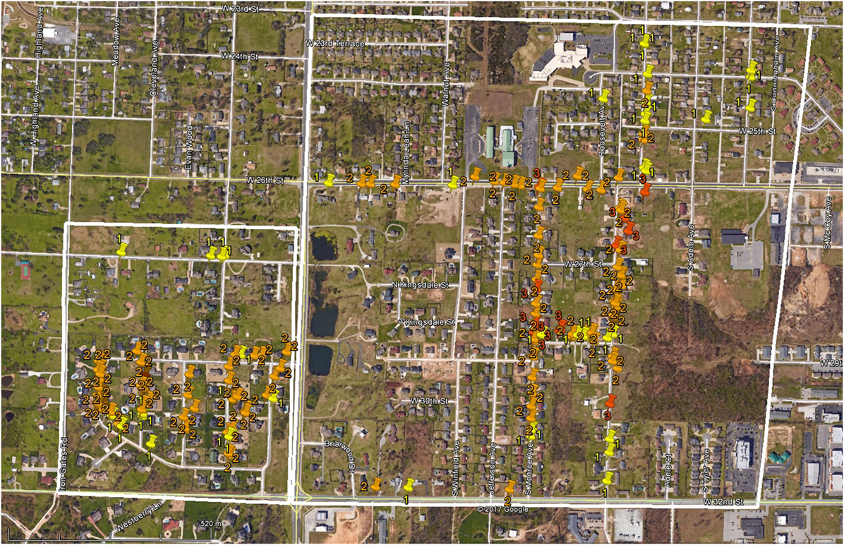
Figure 4. West end of tornado damage path following the May 22, 2011 tornado in Joplin, MO; the present study regions are outlined in white.
Two study areas, outlined in white on Figure 4, are analyzed and the occurrence of different failure modes is assessed. The damage photos at the marked locations were inspected and the perceived mode of failure is noted. In this pass through the data, each separate residence was assessed as to whether the damage appeared to be RTWC, sheathing, or framing failure. Beyond roof damage, wall failures corresponding to DOD-7 are included. The study areas were selected based on the characteristics of the houses. Historical imagery from Google Earth is used to identify the original shape of the studied roofs. Region 1, on the left side of Figure 4, is found to contain houses that appeared to be newer, most with steep-sloping hip roofs and large building footprints. The homes in Region 2 mostly appear to be older, masonry homes with shallow wood-framed roofs.
The results of the statistical analysis are shown in Table 2. As shown, in Region 1, 56% of the houses with relevant damage failed through partial framing failure, while 35% showed signs of failure of the RTWC. Figure 5 shows an example of the steep-sloping hip roofs visible throughout this neighborhood, with an aerial image showing how the surface area of the roof was affected by the failure. In many instances, the largest surfaces of the roof were removed, while parts of the structure enclosing smaller spaces remained in place. Many of these structures also appeared to be of stick-frame construction.
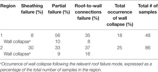
Table 2. Occurrence of residential roof failure modes in selected neighborhoods of Joplin, MI.
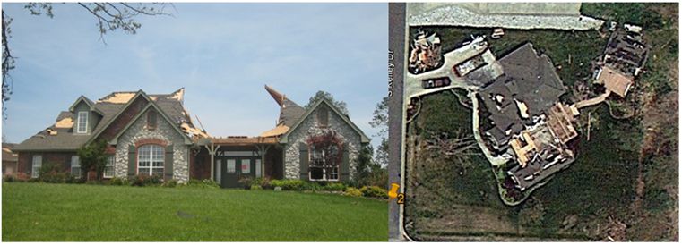
Figure 5. Example of typical hip roof failure in Region 1, including an aerial photo showing the footprint of the partial failure (image source: Dr. David Prevatt, Google Earth).
The occurrence of failure types in Region 2 is different from that of Region 1; the distribution of roof failures is more uniform across three modes, while Region 1 shows a higher occurrence of failures that could be considered major roof failures, i.e., falling under DOD-6. In Region 2, 33% showed partial framing failures, while 37 and 30% suffered RTWC and sheathing failures, respectively. To understand the progression of damage, houses suffering wall collapse are counted based on the observed mode of roof failure assumed to precede the wall damage. For example, in Region 1, 10% of houses suffered partial roof-framing failures and wall collapse, while 8% suffered failure of the RTWC and wall collapse. This results in 18% occurrence of wall collapse in the region. Relationships between the wall and roof failure modes require further study to identify the causal effects of each mode of roof failure.
The shift in occurrence of certain failure modes between the two regions may be the result of several factors; however, it is noted that many of the houses in Region 2 appeared to be of older construction than those in Region 1 and had lower-sloping roofs. While this observation may suggest that roof slope contributes to the occurrence of framing failures, it is not apparent what other factors may have had an additional impact. For example, the lack of lateral restraint in older houses may have led to increased occurrence of wall collapse. In the example shown in Figure 6, partial roof-framing failure occurred. However, this failure may have occurred due to the tree debris visible on top of the failed roof. Other instances of partial failure in Region 2 are similarly ambiguous, and because Region 2 was downwind of Region 1, debris likely played a larger role. In any case, in both regions, partial failures are found to occur at least as often as other modes of roof failure. More work is required to obtain a complete set of statistics on these failures and better define the regional conditions that may contribute to their occurrence.
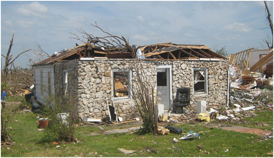
Figure 6. Partial hip roof failure in Region 2 (image source: Dr. David Prevatt).
Analytical Method
Approach and Assumptions
A numerical modeling method is developed and verified to analyze the internal load effects and strength behavior of the components of a wood-frame roof under wind uplift. Following model development to obtain member forces, the element capacities are calculated. The results from the chosen finite element modeling method are combined with estimated element capacity values. This allows the strength performance of the structural components to be assessed in the form of relative demand-to-capacity (D/C) ratios, and possible locations of vulnerability to be identified. In the present work, the term “element” refers to both the lumber framing members and the connections between them. Both types of elements comprise links in the vertical load path and potential failures may originate in either one. A detailed explanation of this work can be found in the study by Stevenson (2017).
Differences between roof construction methods, such as truss framing and stick framing, are assessed to determine the relative likelihood of framing failure in each type. The capacities of the roof-framing elements are also compared to that of the RTWC to provide a point of reference for relating the present results to commonly observed failure modes with well-established wind speeds (i.e., DOD-6). Assuming proper construction in the analyses allows for identification of gaps in current design, if failure is found to be likely. Otherwise, the findings would confirm improper construction in houses with observed failures.
Demand–Capacity Analysis of Trussed and Stick-Frame Roof Sections
To understand the possibility of member or connection failure in a hip roof frame, the load effects due to wind uplift on the framing elements must be determined and compared to the elements’ capacities to resist those effects. Accurate analysis of wood structures must account for the anisotropic properties of wood, the complex behavior of the connections, and numerous possible failure modes. The published literature provides detailed information on modeling nonlinear behavior and establishing failure criteria for certain roof components, but there is limited information available on other elements and stick-frame construction. To obtain comparable results and use consistent methods across different construction types, the analysis of all structures for the present study is limited to the linear range of material behavior. Elements likely to fail first are identified based on relative, linear D/C ratios. This is sufficient to test the hypothesis of partial framing failures, although further analysis would be required to develop fragility curves.
To observe the linear load effects on the members and connections of a roof system, element forces are obtained through finite element modeling using SAP2000. Individual trusses and components of stick-frame roofs are modeled under uniform, negative external pressure, and resulting axial forces and moments are used to assess the demand on each element. As mentioned, additional details on the model verification and analysis method are provided by Stevenson (2017).
Hip Roof Designs Used in Analysis
Wood-frame construction in Canada and the US take similar approaches in which prescriptive or conventional designs are predominant (Canada Mortgage and Housing Corporation, 2014). For the roof structure, these approaches consist of following documents such as the International Residential Code or Part 9 of the National Building Code of Canada to determine member size, spacing, and fastener requirements. In Canada, these requirements are taken from tabulated values based on the design snow loads.
Prescriptive design encompasses both stick-frame and trussed roofs, although the trusses themselves are required to be engineered, and come with site instructions for care, handling, and installation. Metal-plate-connected (MPC) trusses are designed, based on a tributary load distribution, by companies who were specialized in their fabrication. They are becoming the predominant form of new residential roof construction, at least in Canada (Canada Mortgage and Housing Corporation, 2014). However, stick framing is still used and much of the aging housing stock consists of stick-frame construction. Trussed and stick-frame structures both require consideration in the present study because both the types of roof have been observed to fail in the available survey data.
The two-dimensional D/C analysis in this work uses a single MPC truss, based on those used in the full-scale hip roof tested by Henderson et al. (2013). Figure 7 illustrates the layout of the truss; only half of the truss is shown due to symmetry. Following analysis of the truss, a stick-frame hip roof was designed to match the profile and plan geometry of the trussed roof from Henderson et al. (2013), in order to provide a point of comparison.
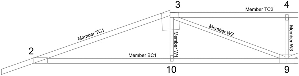
Figure 7. Half of the modeled truss, with joints and members labeled.
For the stick-frame roof, Section 9.23 of the NBCC (Canadian Commission on Building and Fire Codes, 2010) is used to determine the appropriate member placement and sizing requirements, in addition to the minimum number and direction of nails in each joint. The resulting structure is illustrated in Figure 8 with member sizes and spacing labeled. The member layout of stick-frame roofs induces load sharing between the faces and individual members of the roof. The hip rafter transfers loads between members on adjacent faces of the roof and the sheathing plays a role in the member-to-member system effects across a single face. Due to this layout, it is not possible to extract a two-dimensional cross-section from the roof for analysis, as was effectively done in the trussed roof. Instead, the present analysis of the stick-frame roof is simplified by studying a single, representative jack rafter. Upon inspection, the rafters nearest to the center of the roof are deemed to be under the highest demand under roof pressures, due to having the longest unsupported spans. The central jack rafters are expected to experience the highest moments and shear internal forces, and their joints will need to resist the largest support reactions. The faces of the roof are identical and so the selected jack rafter, shown in Figure 9, represents four different jack rafters within the roof.
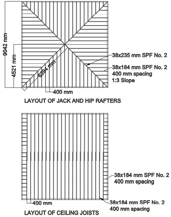
Figure 8. Plan view of designed stick-frame hip roof.
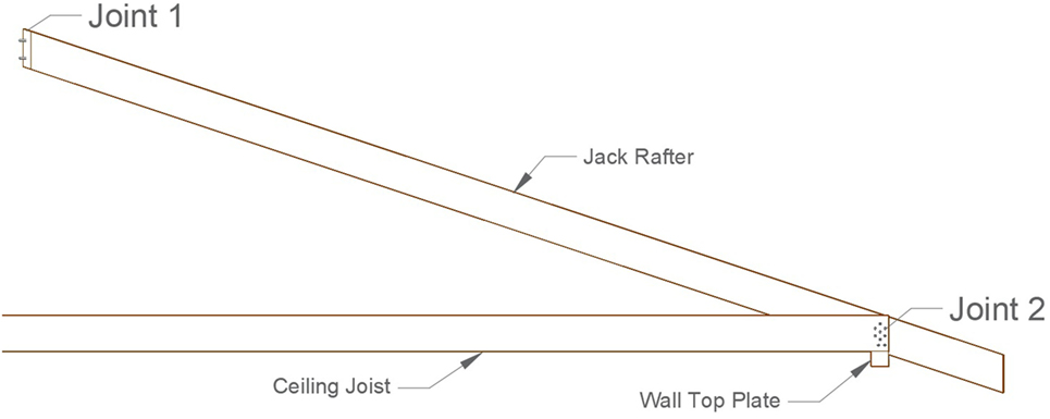
Figure 9. Illustration of the jack rafter selected for the stick-frame analysis.
Numerical Modeling of Wood-Frame Hip Roofs
The model development strategy in this study is to assess whether more than one simplified model analog can be used in combination, to obtain the maximum possible load effects on every element in a truss. This envelope approach was considered appropriate for the present objectives because, by comparing the capacity of every element to its worst possible scenario of loading, all vulnerable elements can be identified without wasting computational or experimental resources on obtaining sufficient data to make nonlinear modeling possible. Another benefit of using the maximum forces is that it may reveal critical conditions that are possible but may not have been considered previously.
The maximum demand results for the truss case are found to come consistently from a combination of two model analogs. One of the models uses all pinned joints and the other uses all rigid joints. The geometric analog is modeled such that the truss chord members act about their bottom faces, and the web members are modeled along their centroids. For the truss case, member and joint force results are extracted from both models and processed to provide the maximum demand values on the truss elements. The maximum demand on the stick-frame rafter is also obtained from two models; one with pinned supports and the other with rigid supports. In the stick-frame case, analysis of a single rafter can easily be accomplished through hand calculations. However, SAP2000 is used so that the selected rafter could be modeled with pinned and rigid joint behavior at the supports, and the maximum force results from both cases could be obtained, similar to the method used in the truss analysis.
The D/C analysis is carried out using the demand results following the models of the truss under 3.25 lb/in (0.57 N/mm) uniform uplift. Wind uplift forces are modeled as negative external pressures, acting perpendicular to the face of the roof, and the weight of the structure is included as a dead load. This load is calculated based on the directional procedure from ASCE 7-10 (Structural Engineering Institute, 2010), using a basic wind speed of 71.5 mph (115 km/h). Through preliminary modeling, this wind speed was found to correspond to the point at which the D/C ratio for the RTWC is equal to 1. This is considered to represent the uplift force at which the first element of the truss is expected to fail. For the stick-frame case, the pressure corresponding to 71.5 mph is multiplied by the tributary area supported by the rafter, resulting in a uniformly distributed load of 2.17 lb/in (0.38 N/mm).
It is important to note that the basic wind speed of 71.5 mph does not represent tornado wind speeds and would require adjustment to allow for direct comparison to DOD-6 for residential structures. However, some observations can be drawn from the literature based on this result. Morrison and Kopp (2011) tested toenail connections under realistic wind loading, and similarly related the strength results back to the main wind force resisting system, and components and cladding design wind speeds used in ACSE 7-05. The 71.5 mph wind speed is consistent with the estimates given in Table 5 of Morrison and Kopp, which neglect load sharing between adjacent connections. When considering load sharing, the design wind speeds in Morrison and Kopp (2011) increase.
The applied 71.5 mph wind speed is much lower than the failure wind speeds estimated by the fragility analyses by Kopp et al. (2016) and Gavanski and Kopp (2017). Both studies considered load sharing and found that at the median probability of failure, the wind speed causing RTWC failure in a hip roof is nearly 155 mph (250 km/h). Beyond the discrepancy due to load sharing, different assumptions regarding internal pressure, roof shape, and wind direction can lead to significant differences in the estimated wind speeds. It is important to recall that the present, two-dimensional study focuses on relative vulnerabilities within the hip roof frame and does not claim to identify the failure wind speeds. The agreement between the adjusted wind speed and Morrison and Kopp’s ASCE 7-05 estimates confirms the accuracy of the methodology.
Capacity Calculations
The minimum capacities of each element in the models are calculated for comparison with the maximum demand in the D/C analysis. The trusses in Henderson et al.’s (Henderson et al., 2013) hip roof used SPF No. 2 sawn lumber, connected by MiTek MII-20 truss plates. Plate strength data sheets, prepared by the manufacturer in accordance to Canadian requirements for truss plate testing (Institute for Research in Construction, 2009), were obtained and are used in the capacity calculations. Relative to the member capacity assessment, which is done based on tabulated values in the Canadian Wood Design Handbook (Canadian Wood Council/Canadian Standards Association, 2010), joint capacities require significant effort to estimate accurately. The Truss Plate Institute of Canada (2014) design specifications for MPC trusses are used for the connection capacity calculations in this study, in addition to the equation proposed in Lewis et al. (2006) for the connection moment capacity.
Joint capacity calculations include determining the capacity of the steel plate, the wood member, and the interaction between the two in the relevant directions (Truss Plate Institute, 2007; Truss Plate Institute of Canada, 2014). In the stick-frame case, the nailed connection capacities of the two member supports are estimated based on unfactored design values and equations from the Canadian Wood Design Handbook (Canadian Wood Council/Canadian Standards Association, 2010). Depending on the direction of loading, the required support capacity calculations include those for nail withdrawal resistance and lateral resistance.
The code capacity equations typically include material resistance factors, which are neglected in this D/C analysis. The equation from the study by Lewis et al. (2006) does not include resistance factors, but the discussion and test results from their study showed that the proposed equation was adjusted to include an inherent factor of safety of 1.5. This factor of safety is removed in the current analysis. Sample capacity calculations and notes, including relevant code equations and clauses, for all required modes of joint capacity are provided by Stevenson (2017). For reference, Figure 7 shows the joints and members of the truss, labeled per the convention used in the analysis, and Figure 9 shows that for the modeled jack rafter.
Demand–Capacity Results
Separate tables of the maximum demand and minimum capacity results are shown by Stevenson (2017). In the present article, the extreme D/C ratios for each element of the truss and rafter models are shown in Tables 3 and 4, respectively. The “vulnerable” elements—those with D/C ratios closest to 1—are indicated by bolded font. The joints with “N/A” D/C values either develop compression in the model results or contain members that are continuous and, therefore, transfer load through the member rather than the joint. The results from Table 3 are also shown schematically in Figure 10. As can be seen, the D/C ratios for the members and joints vary greatly throughout the truss.

Table 3. Demand-to-capacity (D/C) ratios and governing failure mode for the modeled truss under 3.25 lb/in (0.57 N/mm) uplift.
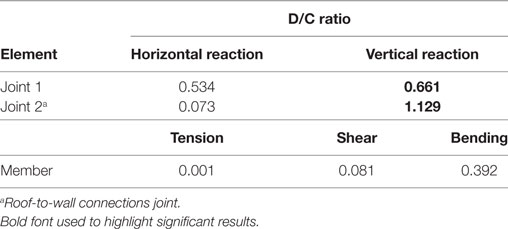
Table 4. Member and joint demand-to-capacity (D/C) ratios for the modeled stick-frame section under 2.17 lb/in (0.38 N/mm) uplift.
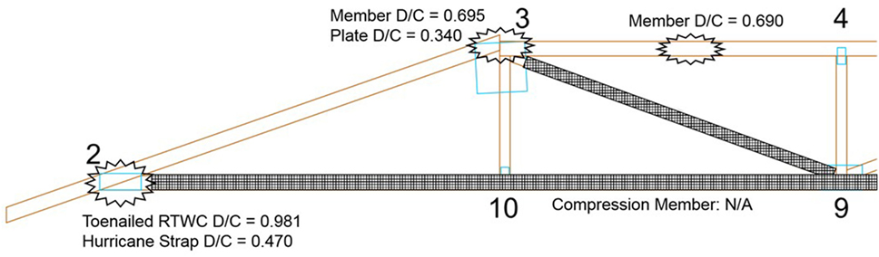
Figure 10. Schematic of failure locations in the truss, based on results of the demand-to-capacity (D/C) analysis.
The preliminary results obtained from analysis of the hip roof truss show that the toenailed RTWC has the lowest relative strength by a 40% difference, with a D/C ratio of 0.981 compared to the next highest ratio of 0.695 in the top chord member at Joint 3. Possible variations in the load path, element capacities, and truss geometry and tolerances could result in shifts in any of the D/C ratios; however, since the analysis is based on taking extreme demand values for the framing elements, it is unlikely that deviations in the two lowest D/C ratios will result in changes to the present finding. It is expected that toenailed RTWCs will almost always fail first in the plane truss case. However, this conclusion does not hold true in the case where hurricane straps are employed at the RTWC. In this case, the D/C ratio of the hurricane strap RTWC is 0.470, which is compared again to the 0.695 D/C in the top chord. Application of even the most basic hurricane strap could shift failure into the framing components of the truss.
Under the same wind uplift as the truss, the results show that the jack rafter is also most vulnerable at the toenailed RTWC. The stick-frame analysis does not include the uplift capacity of an RTWC with hurricane straps. However, introduction of straps at the RTWC is expected to result in failure at Joint 1, since this location has a relatively high D/C ratio. The next weakest connection, at Joint 2, consists of seven nails joining the rafter to the ceiling joist. It has a much higher capacity of around 5,000 N.
The stick-frame results are similar to the results of the truss analysis in two ways. First, they reaffirm the common expectation that a toenailed RTWC is likely to be the most vulnerable element of a hip roof at this slope. The stick-frame results also pinpoint the connection at the ridge of the roof as being the next-most vulnerable element. In both situations, variabilities in the roof behavior and connection parameters make it possible that other failures may take place. This is especially plausible when construction errors, degrading members, and outdated design standards—to which older stick-frame houses were built—are considered.
Limitations
The present statistical and D/C analyses are successful in proving the hypothesis that framing failures in hip roofs are possible (and common) and suggest some conditions that may influence the mode under which a wood-framed hip roof may fail. Beyond this conclusion, it is important to note the limitations of the two-dimensional modeling method. To understand the problem of framing failures in detail, three-dimensional models, which account for load sharing and the effects of sheathing, must be developed. Due to the lack of data and published information to assist with modeling metal plate connections and stick-frame structures, it was not deemed economical to pursue detailed three-dimensional models in the current study.
Additional work should also assess the possible variations that exist in the demand and capacity components of the current results. At the element level, there are many parameters that may cause the behavior of the roof structure to vary significantly. These parameters relate to joint configurations and tolerances, the variability of wood material properties, and the differences in fasteners provided by different manufacturers. At a larger scale, design methods differ across regions, companies, and even individual engineers, and construction of homes is not normally subject to extensive quality control. The likelihood of construction errors and differences in design may be high. These changes could shift the possible results significantly. Understanding framing failures, beyond deeming them theoretically possible, is an important next step in the improvement of building codes as well as the EF-Scale.
Additional Discussion of Observed Stick-Frame Failures
The hip roof-framing failures introduced in this paper describe several different cases and factors that may lead to framing vulnerabilities. The results from the D/C analysis verify that loss of members or faces of a stick-frame hip roof may be likely; however, the progression of failure of large sections of the roof is not well defined. Upon revisiting the damage survey data and the report from the Moore, OK tornado (Graettinger et al., 2014), an additional mode of failure related to the stick-frame case was noted. This mode may point to improper construction of the outer roof frame, or to the potential impact of cascading failures caused by load sharing in stick-frame structures.
In Figure 11, partial framing failure and removal of large sections of the roof appears to have occurred. Upon closer inspection, however, it becomes apparent that the ceiling joists and the ceiling beneath them are intact. Only the external rafters and attached sheathing have been removed or damaged. Based on the results of the D/C analysis for the stick-frame case, this type of failure is unlikely, due to the relatively robust connection between the rafter and the ceiling joist. The RTWC and the connection along the ridge of the roof appear to be much more vulnerable in analysis, in comparison to the seven-nail joint previously mentioned. The pictured failures may have occurred due to improper or missing fasteners between the rafter and the joist at the wall top plate or initiated as failure of the upper rafter joint. Additionally, system effects may have led to progressive, cascading failure of adjacent joints, resulting in removal of entire faces of the roof following initiation at a single point.
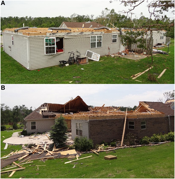
Figure 11. Examples of partial stick-frame, hip roof failure with ceiling joists intact. (A) Complete removal of outer roof framing. (B) Partial removal of several faces of the roof (image source: Dr. David Prevatt).
As mentioned, the D/C analysis for the stick-frame case did not predict that the rafter-to-wall connection would be vulnerable due to its relatively robust connection to the ceiling joist. According to the rafter capacity calculations, the rafter-to-top plate connection should have a capacity of 5,000 N, resulting in a D/C ratio of 0.2. Closer inspection of the photos suggests that there were nailed connections at the ends of the intact joists; however, it does not appear that there were more than a few nails. Keeping in mind that these houses were not designed to the same codes as the hypothetical roof in the present study, exploration of regional prescriptive design requirements in the US is required to determine whether these connections are meant to include more nails.
The failures shown in Figure 11, and many other similar failures, are interesting because they would be objectively classified within DOD-6 for residential roofs; however, this may be an inaccurate assumption. This is an important point for further exploration because it may influence refinements to the EF-Scale for different residential design methods, or even suggest a new DOD for stick-frame structures.
Conclusion
Damage survey observations and statistical assessments presented herein extend the current understanding of residential roof failures, and introduce a previously unresearched failure mode characterized by damage to the roof-framing components. Statistics of observed damage in sample neighborhoods from Moore, OK and Joplin, MI have shown that framing failures may occur as often as the well-understood RTWC and sheathing failure modes under EF1 and EF2 wind speeds. While hip-roofed homes are commonly understood to be more resistant to wind damage than those with gable roofs, the observations of partial framing failures reveal that hip roofs may be more vulnerable than previously expected.
A numerical modeling and analysis method is developed to further investigate the behavior of common hip roof-framing components. Both trusses and stick-frame structures are assessed to provide a comparative study of the two construction methods. The results of a two-dimensional D/C analysis for the trussed and stick-frame cases have been used to understand the likely locations of vulnerability in the framing structure, and test the hypothesis of roof failure originating within the framing structure. A simplified, load-envelope method of modeling and the D/C analysis have shown the ability to identify locations of vulnerability in both trussed and stick-frame roof sections under wind uplift. The observational and numerical studies yielded the following key findings:
• In the neighborhoods studied using geo-located damage photos, up to 56% of houses in the EF1–EF3 range of damage suffered partial roof-framing failures.
• The type of construction may have important implications on the type of roof failure that a house will suffer. In the neighborhoods which had 56% of residential roof damage occur as partial roof-framing failures, the houses appeared to be of newer, stick-frame construction with large footprints and steep-sloping roofs. Another region, which showed 33% partial failures, contained houses that appeared older, with lower-sloping roofs and masonry wall structures. It is also noted that some of the partial failures observed in this region may have involved debris impact.
• In the observed steep-sloping roofs, it should be noted that many of the observed failures occurred in an asymmetric manner, i.e., one of the large faces of a roof failed while the opposite remained intact. In contrast to the modeled roof, which is subjected to uniform uplift pressures in the present analysis, roofs with steeper slopes are likely to experience an imbalance of wind loads on the windward and leeward faces. The impact of changing roof slopes, plan shapes, and direction of wind loading will be investigated further, in addition to material strength and stiffness variabilities, in later stages of this research.
• An additional failure mode involving entire or partial removal of the entire outer shell of stick-frame roofs is identified. These failures suggest that the rafters comprising the sloped portion of stick-frame roofs may lack proper fastening at the ridge of the roof, or to the ceiling joists and the walls beneath them. Loss of the outer shell of the roof through this failure mode would be classified as DOD-6 damage upon inspection; however, it may actually occur at lower wind speeds than those required for failure of the RTWC, as indicated by the current D/C analysis. This mode of failure requires further study and additional statistics of its occurrence will be included in future work.
• When toenailed RTWCs are used, MPC trusses under uniform uplift are most likely to fail through the RTWC, resulting in loss of the entire framing structure and ceiling. When hurricane straps are supplied, the onset of failure may shift to the truss members and connections (or to the sheathing). The critical modes of failure within the truss structure were found to be associated with member and joint moments under uplift. Namely, the top chord joints (Joint 3) and the horizontal top chord member (TC2) in the modeled truss were found to be relatively vulnerable, with D/C ratios of 0.70 and 0.66, respectively, while the toenailed RTWC D/C ratio was equal to 1. The demand due to moment in the top chord members are heightened by the tensile axial forces induced on these members through typical truss behavior.
• The stick-frame analysis case also found toenailed RTWCs to be the most vulnerable component in the two-dimensional analysis. The D/C ratio of the stick-frame RTWC is found to be 1.129, under the same applied uplift as the truss. However, the upper rafter joint is also found to have a relatively high D/C ratio of 0.66. Inspection of the damage survey photos suggested that the failed stick-frame roofs may have contained less-robust joints than required in design.
• Comparison of the two-dimensional analyses for the truss and stick-frame cases suggests that stick-frame roofs contain more highly vulnerable elements. Under equivalent wind uplift, the D/C of the truss RTWC is 0.98, while the RTWC of the stick-frame jack rafter is 1.12. This is as expected; however, the effect of load sharing is an important factor, especially for the stick-frame case, which is not considered in this study.
Author Contributions
SS is a Ph.D. student under the co-supervision of GK and AA. This research is a portion of the work completed for SS’s Master’s thesis. The hypothesis and approach to the work were conceived collaboratively by the authors. SS performed all analyses, interpreted data, and drafted, evaluated, and drafted the manuscript for submission under the direct supervision of GK and AA. GK and AA advised design of the analyses, interpretation of results, and evaluation of the manuscript for publication. The authors agree to be accountable for all aspects of the work in ensuring that questions related to the accuracy or integrity of any part of the work are appropriately investigated and resolved.
Conflict of Interest Statement
The authors declare that the research was conducted in the absence of any commercial or financial relationships that could be construed as a potential conflict of interest.
Acknowledgments
This work was funded by the Natural Science and Engineering Research Council of Canada under the Collaborative Research and Development program in collaboration with Chaucer Syndicates Ltd. and the Institute for Catastrophic Loss Reduction (ICLR). The ongoing support from Mr. Gero Michel (Chaucer) and Mr. Paul Kovacs (ICLR) is gratefully acknowledged. The authors are also grateful to Drs. David Prevatt (University of Florida) and David Roueche (Auburn University) for providing damage survey data, valuable suggestions, and relevant literature and to the National Science Foundation (NSF) for providing financial support to the field research leading to the generation of their damage survey data. The aforementioned damage surveys were supported by the NSF research grant 1150975 and the NSF RAPID grants program.
References
Amini, M. O., and van de Lindt, J. W. (2014). Quantitative insight into rational tornado design wind speeds for residential wood-frame structures using fragility approach. J. Struct. Eng. 140. doi: 10.1061/(ASCE)ST.1943-541X.0000914
Canada Mortgage and Housing Corporation. (2014). Canadian Wood-Frame House Construction, 3rd Edn. Canada: Government of Canada.
Canadian Commission on Building and Fire Codes. (2010). National Building Code of Canada, 13th Edn. Ottawa: National Research Council of Canada.
Canadian Wood Council/Canadian Standards Association. (2010). Wood Design Manual: The Complete Reference for Wood Design in Canada. Ottawa, ON: Canadian Wood Council.
Environment Canada. (2013). Environment and Climate Change Canada: Enhanced Fujita Scale. Available at: https://ec.gc.ca/meteo-weather/default.asp?lang=En&n=41E875DA-1
Gavanski, E., and Kopp, G. A. (2017). Fragility assessment of roof-to-wall connection failures for wood-frame houses in high winds. J. Risk Uncertainty Eng. Syst. 3. doi:10.1061/AJRUA6.0000916
Graettinger, A. J., Ramseyer, C. C., Freyne, S., Prevatt, D. O., Myers, L., Dao, T., et al. (2014). Tornado Damage Assessment in the aftermath of the May 20th 2013 Moore Oklahoma Tornado. Tuscaloosa, AL: The University of Alabama.
Henderson, D. J., Morrison, M. J., and Kopp, G. A. (2013). Response of toe-nailed, roof-to-wall connections to extreme wind loads in a full-scale, timber-framed, hip roof. Eng. Struct. 56, 1474–1483. doi:10.1016/j.engstruct.2013.07.001
Institute for Research in Construction. (2009). Evaluation Listing CCMC 11996-L: MT-20 and MII-20. Ottawa, ON: National Research Council of Canada.
Kopp, G. A., Hong, E., Gavanski, E., Stedman, D., and Sills, D. M. (2016). Assessment of wind speeds based on damage observations from the Angus (Ontario) tornado of 17 June 2014. Can. J. Civil Eng. 44, 37–47. doi:10.1139/cjce-2016-0232
Kopp, G. A., Morrison, M. J., and Henderson, D. J. (2012). Full-scale testing of low-rise residential buildings with realistic wind loads. J. Wind Eng. Ind. Aerodyn. 104–106, 25–39. doi:10.1016/j.jweia.2012.01.004
Lewis, S. L., Mason, N. R., Cramer, S. M., Wert, D. C., O’Regan, P. J., Petrov, G., et al. (2006). “Design of metal plate connected wood truss joints for moment,” in 9th World Conference on Timber Engineering (Portland, OR). Available at: http://support.sbcindustry.com/Archive/2006/aug/Paper_322.pdf
Meecham, D. (1992). The improved performance of hip roofs in extreme winds – a case study. J. Wind Eng. Ind. Aerodyn. 43, 1717–1726. doi:10.1016/0167-6105(92)90583-V
Meecham, D., Surry, D., and Davenport, A. G. (1991). The magnitude and distribution of wind-induced pressures on hip and gable roofs. J. Wind Eng. Ind. Aerodyn. 38, 257–272. doi:10.1016/0167-6105(91)90046-Y
Mehta, K. C. (2013). Development of the EF-scale for tornado intensity. J. Disaster Res. 8, 1034–1041. doi:10.20965/jdr.2013.p1034
Morrison, M. J., and Kopp, G. A. (2011). Performance of toe-nail connections under realistic wind loading. Eng. Struct. 33, 69–76. doi:10.1016/j.engstruct.2010.09.019
Prevatt, D. O., Coulbourne, W., Graettinger, A. J., Pei, S., Gupta, R., and Grau, D. (2013). Joplin, Missouri, Tornado of May 22, 2011: Structural Damage Survey and Case for Tornado-Resilient Building Codes. Reston, VA: American Society of Civil Engineers.
Prevatt, D. O., van de Lindt, J. W., Graettinger, A. J., Coulbourne, W., Gupta, R., Pei, S., et al. (2011). Damage Study and Future Direction for Structural Design Following the Tuscaloosa Tornado of 2011. Gainesville, FL: University of Florida.
Ramseyer, C., Floyd, R., Holliday, L., and Roswurm, S. (2014). “Influence of lateral load bracing systems on damage and survivability of residential structures impacted by the Moore, Oklahoma, tornado of May 20, 2013,” in Proceedings of the Structures Congress 2014 (Boston, MA: ASCE), 1484–1507.
Simmons, K. M., Kovacs, P., and Kopp, G. A. (2015). Tornado damage mitigation: benefit-cost analysis of enhanced building codes in Oklahoma. Weather Clim. Soc. 7, 169–178. doi:10.1175/WCAS-D-14-00032.1
Sparks, P. R., Schiff, S. D., and Reinhold, T. A. (1994). Wind damage to envelopes of houses and consequent insurance losses. J. Wind Eng. Ind. Aerodyn. 5, 145–155. doi:10.1016/0167-6105(94)90023-X
Standohar-Alfano, C. D., and van de Lindt, J. W. (2016). Tornado risk analysis for residential wood-frame roof damage across the United States. J. Struct. Eng. 142. doi:10.1061/(ASCE)ST.1943-541X.0001353
Stevenson, S. A. (2017). Analysis of Framing Failures in Wood-Frame Residential Roofs under Wind Load. Master’s thesis. London, ON: The University of Western Ontario.
Structural Engineering Institute. (2010). ASCE 7-10 Minimum Design Loads for Buildings and Other Structures. Reston, VA: American Society of Civil Engineers.
Truss Plate Institute. (2007). National Design Standard for Metal Plate Connected Wood Truss Construction. Alexandria, VA: American National Standards Institute (ANSI).
Truss Plate Institute of Canada. (2014). Truss Design Procedures and Specifications for Light Metal Plate Connected Wood Trusses. Bradford, ON: TPIC.
van de Lindt, J. W., Pei, S., Dao, T., Graettinger, A., Prevatt, D. O., Gupta, R., et al. (2013). Dual-objective-based tornado design philosophy. J. Struct. Eng. 139, 251–263. doi:10.1061/(ASCE)ST.1943-541X.0000622
Keywords: wood-frame structures, tornado damage, Enhanced Fujita Scale, hip roofs, finite element modeling, degrees of damage, residential structures
Citation: Stevenson SA, Kopp GA and El Ansary AM (2018) Framing Failures in Wood-Frame Hip Roofs under Extreme Wind Loads. Front. Built Environ. 4:6. doi: 10.3389/fbuil.2018.00006
Received: 03 October 2017; Accepted: 19 January 2018;
Published: 06 February 2018
Edited by:
Weichiang Pang, Clemson University, United StatesReviewed by:
Ioannis Zisis, Florida International University, United StatesThang Nguyen Dao, University of Alabama, United States
Copyright: © 2018 Stevenson, Kopp and El Ansary. This is an open-access article distributed under the terms of the Creative Commons Attribution License (CC BY). The use, distribution or reproduction in other forums is permitted, provided the original author(s) and the copyright owner are credited and that the original publication in this journal is cited, in accordance with accepted academic practice. No use, distribution or reproduction is permitted which does not comply with these terms.
*Correspondence: Gregory A. Kopp, gak@blwtl.uwo.ca