Seismic Behavior of One-Storey Gabion-Box Walls Buildings
 Julio Samayoa
 Simonetta Baraccani
 Luca Pieraccini
 Stefano Silvestri
- 1Central American University, San Salvador, El Salvador
- 2Department of Civil, Chemical, Environmental, and Materials Engineering, University of Bologna, Bologna, Italy
Gabion-boxes, made with steel wire mesh and filled with stones of appropriated size, are normally stacked up one into another to form a retaining wall. Given their reduced costs and the easy availability of their constituting materials, gabion-box walls have been extensively used in developing countries (such as Nepal) also to realize simple one-storey residential buildings. In recent years, many of these structures have been subjected to several strong earthquakes and have shown a good seismic behavior, even if they have never been the object of a proper structural design. In the scientific literature, research studies have been developed on gabion-box walls used as retaining systems, but no investigations have been conducted on the performances of gabion-box walls buildings. In this respect, the general objective of this research work is to give a first insight into the static and seismic behavior of such gabion-box walls buildings through analytical considerations and numerical models. In detail, with reference to a typical 5 m × 5 m plan model, this article investigates the in-plane and out-of-plane seismic responses of its constituting walls, by means of simple analytical interpretations and Discrete Element Method numerical simulations. Even if this study should be considered as a starting point and even if the fundamental cellular behavior of the three-dimensional structure has not been fully taken into account, some criticalities have been disclosed and the order of magnitude of the seismic activation load multipliers has been estimated. The out-of-plane collapse mechanism is characterized by multiplier around 0.15, while the in-plane mechanism multiplier depends on the position of the door in the single wall (0.10–0.20), but it can be easily increased with lintel beams placement. The results are based on the assumptions taken by several authors and have not been verified with experimental tests. Nevertheless, some practical suggestions (basically in terms of spacing and construction details, such as vertical connectors and reinforcing steel knots) can be derived to improve the construction in order to ensure a better seismic behavior.
1. Introduction
In the recent years, gabion structures have been increasingly used in the engineering field. This interest is due to the fact that gabions are environmental friendly and they present several other advantages: versatility, durability, flexibility, permeability, noise proofing, and limited costs.
A gabion-box is a rectangular cage made with steel wire mesh and filled with stones. A gabion-box wall is built-up by stacking vertically each single gabion-box and then joining them with steel wires in order to provide some tensile strength to the entire wall, until the specified height of the wall is reached. In placing the gabion-boxes the vertical joints must be alternated. A gabion-box walls building is a structure composed of adequately interconnected gabion-box walls.
Gabion-boxes are characterized by a significant flexibility that allows the development of large deformations, avoiding brittle and sudden failure mechanisms. However, according to the experimental findings obtained by Agostini et al. (1987) at the laboratories of the University of Bologna, the deformability does not reduce the strength of the structure, but it brings into action all the single resisting elements (steel wire mesh in tension and stones in compression), thus leading to an overall larger capacity of withstanding loads.
Gabion-box structures are versatile, since they have been used in many construction fields and construction types, such as: revetments (for architectural and esthetic solutions), canal linings, weirs and dikes, bridge abutments, offshore breakwaters and beach protection solutions, and retaining walls.
Nowadays they started to be used as a new alternative building technique for houses in developing countries, such as Nepal and India, which are also characterized by a significant telluric activity. From the economical point of view, gabion-boxes are less expensive as compared to the most used construction materials like reinforced concrete, given that stones are usually locally available as filling material. Considering the advantages of the gabion-box walls building system, it could represent an alternative building and post-disaster reconstruction technique in developing countries. Such a technique could be used for individual housing or for community facilities, also in remote locations (difficult to be reached) and poorly supplied areas, since gabion-boxes can be locally manufactured, easily installed without special equipment and highly trained personnel. On the other hand, from a seismic point of view, there are “weight issues” given that the gabions are characterized by significant mass due to the rock filling (it is well known that the seismic forces acting on the structure are proportional to the weight). In the scientific literature, no studies are available regarding the static and seismic behavior of this kind of building structures.
Only limited information is available regarding the simple gabion box component: its basic properties, such as the maximum compression stress, the shear strength and the equivalent linear elastic modulus, were first investigated by Agostini et al. (1987) by means of uniaxial compression tests and shear tests on full size gabions. Afterwards, the experimental results by Agostini et al. (1987) were used by Lin et al. (2010a) for the calibration of a deformation model of a loaded gabion structure in which an apparent total shear modulus was proposed taking into account the compound shear deformation behavior of wire mesh and infilled stone. In the same years, other researchers performed laboratory tests to study the mechanical characteristics of gabion meshes of double twisted hexagonal shape used in China (Yang et al., 2009) and to investigate vertical earth pressure, lateral earth pressure deformation behaviors of reinforcement, potential failure surface and deformation behavior of wall face of gabion retaining wall (Lin et al., 2010b). Recently, Jiang and Wang (2011) performed a further research and obtained the stress-strain behavior of gabion-boxes for both confined and non-confined conditions. More recently, Al Helo et al. (2016) experimentally investigated the mechanical behavior of the wired-mesh gabion-boxes under axial compression load in terms of stress-strain relationship and failure modes.
On the contrary, a plenty of research works is available for gabion boxes used as earth retaining walls, with the primary purpose of providing lateral support for soil or rock. In this respect, a valuable work is represented by the PhD thesis of Jayasree (2008), to which the reader is referred for a complete literature review about the experimental investigations, the analytical studies and the numerical modeling analyses of gabion retaining walls. The objectives were to develop a Finite Element prediction tool capable of simulating the behavior of gabion faced retaining walls and to validate it through experimental tests. Gabions have been also studied as scour-arresting devices on bridge abutments and piers: Ramli et al. (2013) suggested to improve gabion resistance against lateral movement in case of flooding by means of an interlocking configuration instead of the conventional stack-and-pair system. Furthermore, Amato et al. (2015) evaluated the potential of gabions as low-cost roadside barriers.
However, in the scientific literature, there is a clear lack of studies on building structures made up of gabion boxes. This research work aims at providing a first insight into the structural behavior of gabion-box walls buildings with bamboo/timber light roof, focusing on the limitations of the system and on practical suggestions to improve the structural response to seismic action.
In more detail, the present study aims at understanding (i) the static behavior with respect to vertical loads, (ii) the in-plane seismic behavior, and (iii) the out-of-plane seismic behavior of a one-storey gabion-box walls building. The analyses are carried out by means of simple analytical models and Discrete Element Method (DEM) models. Finally, some rules of thumb are proposed for a better dimensioning and construction of this kind of structures in order to achieve an improved seismic behavior.
2. The Case Study
All analyses performed in the present study are referred to an one-storey building composed of four gabion-box walls and a flexible bamboo/timber light roof system, characterized by a 5 m × 5 m plan layout (Figure 1) and a 3 m height. This case study has been selected since it is representative of both (i) a typical independent house building and (ii) a single module of an aggregate community building, in developing countries.
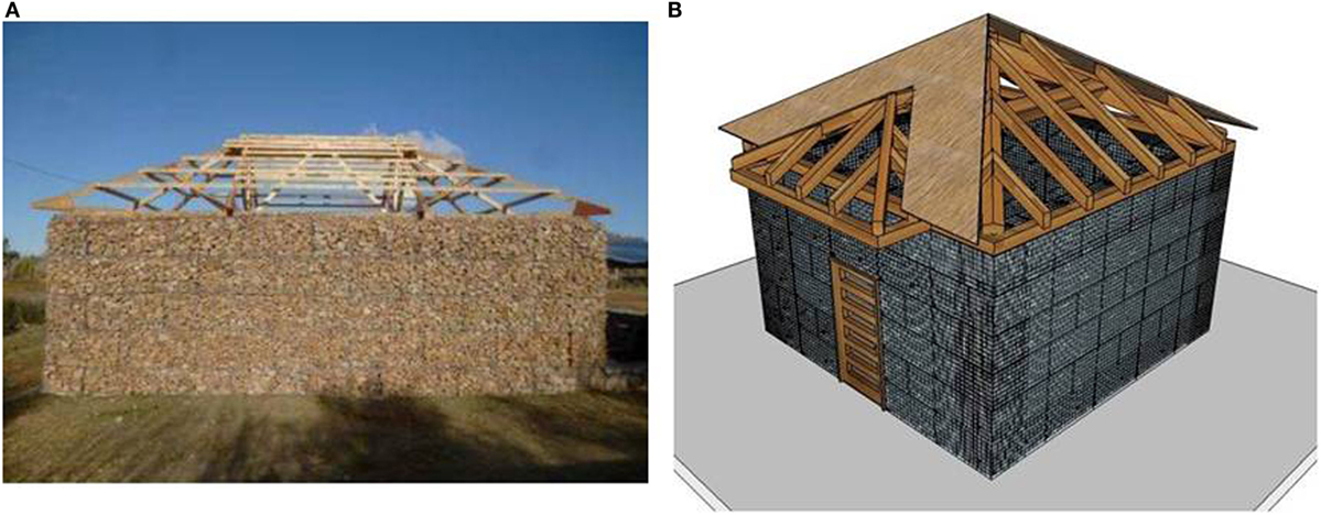
Figure 1. (A) Illustrative photograph (courtesy from A&D—Architecture and Development—www.archidev.com working with architecture sans frontiers Nepal). (B) Sketch of the considered gabion-box walls structure.
2.1. The Gabion-Box
Figure 2A reports a picture of the typical wire mesh used for gabion boxes. Usually (e.g., in El Salvador), the hexagonal openings are characterized by 8 cm × 10 cm dimensions and the diameter of wire is equal to 2.7 mm (for other common dimensions see Table 1 of the work by Lin et al., 2010a). A cover of zinc in the minimum amount of 260 g/m2 is also applied to prevent corrosion. According to Table 1 of the EN ISO 12944-2:1998 (European Committee for Standardization, 1998), for the worst case of very high marine atmospheric-corrosivity category typical of high-salinity coastal areas, assuming a steel thickness loss of about 200 μm per year and a zinc mass loss of 60 g/m2 per year, a life time for the gabion box of about 18 years is expected. However, for the most common case of low atmospheric-corrosivity category typical of rural areas with low level of pollution, assuming a steel thickness loss of about 25 μm per year and a zinc mass loss of 5 g/m2 per year, a life time larger than 150 years is expected and corrosion does not represent an issue.
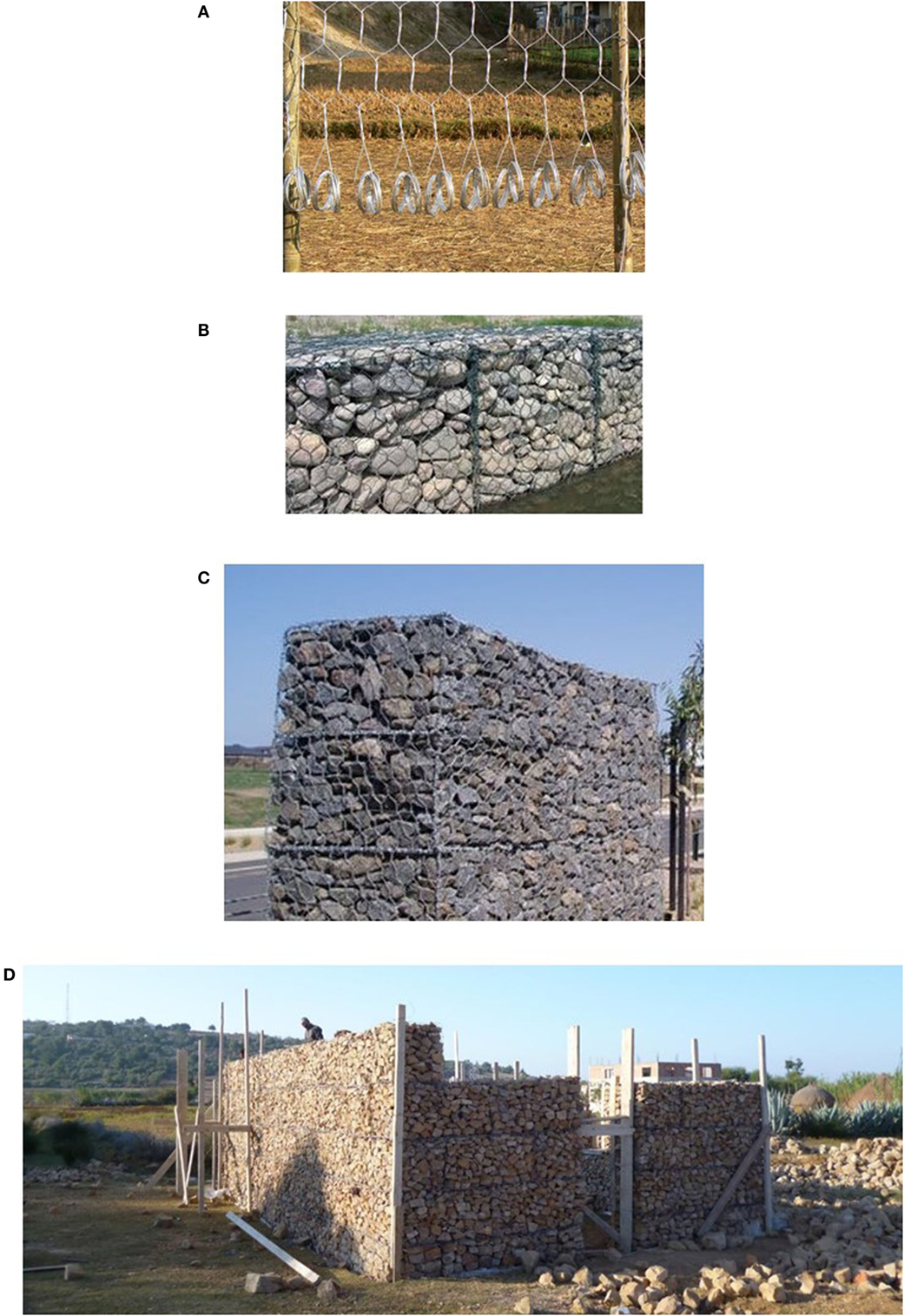
Figure 2. (A) The typical wire mesh. (B) The gabion-box. (C) The gabion-box wall (courtesy from Anping Xingmao Metal Wire Mesh Co., Ltd.). (D) The gabion-box walls building (courtesy from A&D—Architecture and Development—www.archidev.com working with architecture sans frontiers Nepal).
For the infill material of the gabion-box (Figure 2B), stones with adequate frost resistance and adequate hardness should be used. The size of the rocks should be selected according to the spacing of the steel wire mesh. The infill material should be large enough to avoid the flow of the rocks outside the cage: the most appropriate size of the stones varies from 1.5 to 2.5 times the characteristic dimension of the mesh spacing. However, the adoption of medium-low size stones allows a better settlement, faster filling and a better distribution of the contact forces between stones and a major adaptability to the deformations. The infill material is usually deposited inside the cage by placing the stones in a random way.
In the present study, fixed dimensions for the gabion-box simple component are considered: 0.5 m × 0.5 m × 1.0 m (width w × height h × length l).
2.2. The Gabion-Box Wall
Once the gabion-boxes are vertically stacked and bound together, the gabion-box wall (Figure 2C) acts as a monolithic structure, capable of resisting significant compression stresses and limited tensile and shear stresses. The wire mesh works in tension and confines the infill material.
In the present study, the length of each one of the four walls is equal to 5 m. Figure 3 reports the typical positioning of the gabion boxes in order to obtain a wall with a centered 1 m × 1 m window opening and a wall with eccentric 1 m × 2 m (width × height) door opening.
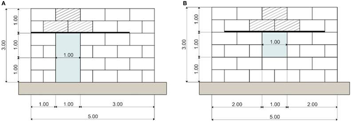
Figure 3. Details and dimensions of walls with openings for (A) door and (B) window.
The upper parts of the openings should be equipped with timber lintel beams. Even if the two gabions above the opening may work as cantilever beams with limited vertical deflection (Agostini et al., 1987), in order to avoid long-term deformations (associated with internal reorganization of the stone filling), two adjacent timber lintel beams with dimensions of 24 cm × 6 cm × 300 cm (width × height × length) should be inserted above the opening.
2.3. The Gabion-Box Walls Building
Orthogonal gabion-box walls are typically connected to obtain a gabion-box walls building (Figure 2D). The connections between perpendicular walls are essential in the seismic behavior of the building to ensure a kind of cellular behavior (like the one pursued in masonry buildings). Thus, the two orthogonal walls should be interlocked, simulating a sort of “LEGO” connection. The walls are typically erected in direct contact with the soil, without providing any local enlargement at the foundation level.
In the present study, the considered building is characterized by two full walls and two walls with openings, with gabion boxes positioned according to the layout shown in Figure 4.
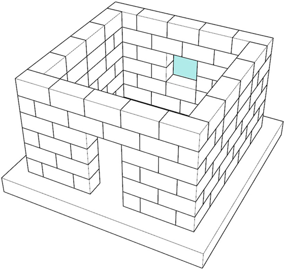
Figure 4. The considered gabion box walls building.
3. Basic Data
In this section some basic properties of the gabion-boxes are recalled from scientific literature. In the present study, all the values that have been considered do not include any safety factor. Only in the final discussion section, safety factors will be introduced.
3.1. Weight
Gabion-boxes are filled with loose rock material. Therefore, in order to compute properly the weight of a single gabion-box, the void ratio of the infill material η should be taken into account. According to Agostini et al. (1987), the void ratio varies between 0.3 and 0.4. In the present study, η = 0.3 has been selected. Thus, considering a value of the unit weight of the rock material equal to 26 kN/m3 and a gabion volume of 0.25 m3, the weight of a simple gabion-box component is about 4.5 kN. Since a total amount of 30 gabion-boxes is required for the full 5 m length wall, the total weight W of a single gabion-box wall results equal to 135 kN.
3.2. “Equivalent” Linear-Elastic Modulus
Gabion-boxes are characterized by a marked non-linear stress-strain relationship under vertical compression, which strongly depends on the vertical stress level and on the lateral confinement conditions.
In the scientific literature, Lin et al. (2010a) proposed a stress–strain relationship for a single gabion-box component in both restricted and unrestricted lateral confinement conditions. By considering a limited compression stress level (less than 100 kPa), the relationship may be assumed linear and the “equivalent” linear-elastic modulus may be taken equal to Er = 4 MPa and Eur = 2 MPa in restricted and unrestricted conditions, respectively.
In the present study, the value of the “equivalent” linear-elastic modulus in unrestricted conditions has been considered in the DEM analyses.
3.3. Shear Strength
The shear strength of a simple gabion-box component is analyzed in order to obtain a relationship between shear strength τ and actual normal stress σn according to the well known Mohr-Coulomb criterion, with reference to two different interfaces:
1. Internal interface: any internal surface within a single gabion box. The interface may lie on a horizontal plan or on a vertical plan.
2. External interface: the interface surface between two adjacent gabion boxes. The interface may lie on a horizontal plan or on a vertical plan.
With reference to the internal interface, the experimental direct shear tests performed by Jiang and Wang (2011) provide the following relationship (cohesion c = 0.56 MPa, internal friction angle φ = 44.8°):
With reference to the external interface, the steel wire mesh contribution is neglected. Also, the construction process as well as the rock filling phase are so that no cohesion is provided and only friction is ensured between the two boxes. Given that no experimental values are available in the literature, half value of the one indicated for the internal interface may be reasonably adopted (friction coefficient μext around 0.45). Therefore:
4. Static Behavior of a Gabion-Box Wall
The stress levels acting on each horizontal layer of the gabion-box wall are computed by taking into account the roof weight and the wall self-weight. Figure 5 shows the free-body diagram of the gabion-box wall subdivided in two portions and highlights the normal stresses exchanged between them. Also, Figure 5 identifies the six layers of gabion boxes which constitute each single wall.
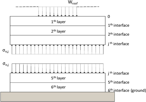
Figure 5. Normal stresses acting on each interface between the gabion-box layers.
The mean value of the normal stress acting at the j-th interface (j = 0, 1, …, 6, see Figure 5) between two layers (layers are identified by i = 1, …, 6) is given by:
where A is the horizontal area of each interface, Wroof is the amount of roof load acting on the considered wall, Wlayer,i is the self-weight of each layer, while Wj is the total weight acting at the j-th interface. In the present study, with reference to the full 5 m length wall, A = 0.5 m × 5 m = 2.5 m2, Wlayer,i = W/6 = 135 kN/6 = 22.5 kN for all layers, and, assuming a roof load equal to 1.00 kN/m2 (snow load is neglected) equally distributed among the four walls, Wroof = 6.25 kN.
Table 1 presents the mean values of the normal stress acting at each interface. In computing the normal stress acting at the roof level, Wroof is considered as uniformly distributed along the 5 m length wall. At each interface, the limited stress value does not represent an issue for gabion box strength which is around 1,500 kPa, according to Lin et al. (2010a). At the ground interface, the stress level is around 57 kPa. This value may be considered acceptable for common soils, even introducing safety factors around 1.5 and 2. However, gabion-box wall could withstand moderate differential settlements thanks to their flexibility (Sublette, 1979).
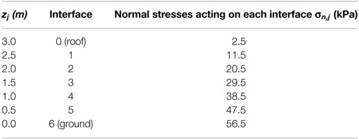
Table 1. Normal stresses.
5. In-Plane Seismic Behavior of a Gabion-Box Wall
In this section, the in-plane seismic behavior of a single gabion-box wall is investigated in order to identify the value of the horizontal acceleration which triggers in-plane failure mechanisms.
Two distinct failure mechanisms can be envisaged: (i) horizontal sliding between adjacent layers and (ii) hinge formation between distinct portions of the gabion-box wall with openings. The diagonal cracking failure, typical of masonry walls, does not straightforwardly apply to this kind of structures, since the wall shows up in “already cracked conditions” for constructive reasons. The failure mechanism which involves a combined action axial force-bending moment at the base of the wall is not relevant for stocky elements.
The analyses are carried out, with reference to the 5 m length walls, under the following assumptions:
1. The effect of the earthquake ground motion is represented by a uniform vertical distribution of horizontal inertia forces, proportional to the peak ground acceleration (PGA). This is due to the low-rise configuration of the building, the stockiness and the high lateral stiffness of the wall, which lead to negligible structural amplification. Consequently, the horizontal seismic shear force acting at the j-th interface of the wall, Vj, is given by:
where g is the gravity acceleration, and α = PGA/g represents the seismic activation load multiplier (see Figure 6).
2. No vertical component of the earthquake ground motion is considered.
3. The gabion-boxes are infinitely stiff and strong in compression and the tensile strength provided by the steel wire is neglected, in accordance with the established approach by Heyman (1966) for the masonry structures.
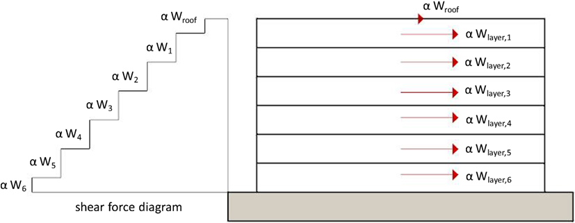
Figure 6. Uniform distribution of lateral seismic forces.
5.1. Sliding Failure of a Gabion Wall without Openings
As far as the horizontal sliding between adjacent layers is concerned, the shear strength against sliding failure at the j-th interface, Rsliding,j, for a wall without openings depends on the value of the vertical normal compressive stress:
The failure is triggered if Vj is larger than the corresponding Rsliding, j. Thus, the value of α that triggers the horizontal sliding of two adjacent layers can be obtained by imposing:
which leads to:
Thus, the acceleration which activates the sliding failure depends simply on the interface friction between adjacent layers, i.e., between adjacent gabion-boxes. If friction is assumed equal to 0.45 according to the considerations made in Section “Shear Strength”, then the activation acceleration is expected to be around 0.45 g. If vertical (steel or timber) connectors or rock elements are inserted in such a way they provide a cutting strength along this interface, the friction coefficient will increase as well as the sliding strength of the wall.
5.2. In-Plane Behavior of a Gabion-Box Wall with Openings
The kinematic theorem is applied to a gabion-box wall with openings, by assuming selected failure configurations in which the hinges formation subdivides the wall in distinct rigid blocks. Figure 7A shows the considered wall with the door opening (dimensions are schematized by symbols A, B, C and D, h and H). Figures 7B,C show the two failure configurations which have been chosen to obtain analytical predictions of the seismic activation load multiplier (α1 and α2).
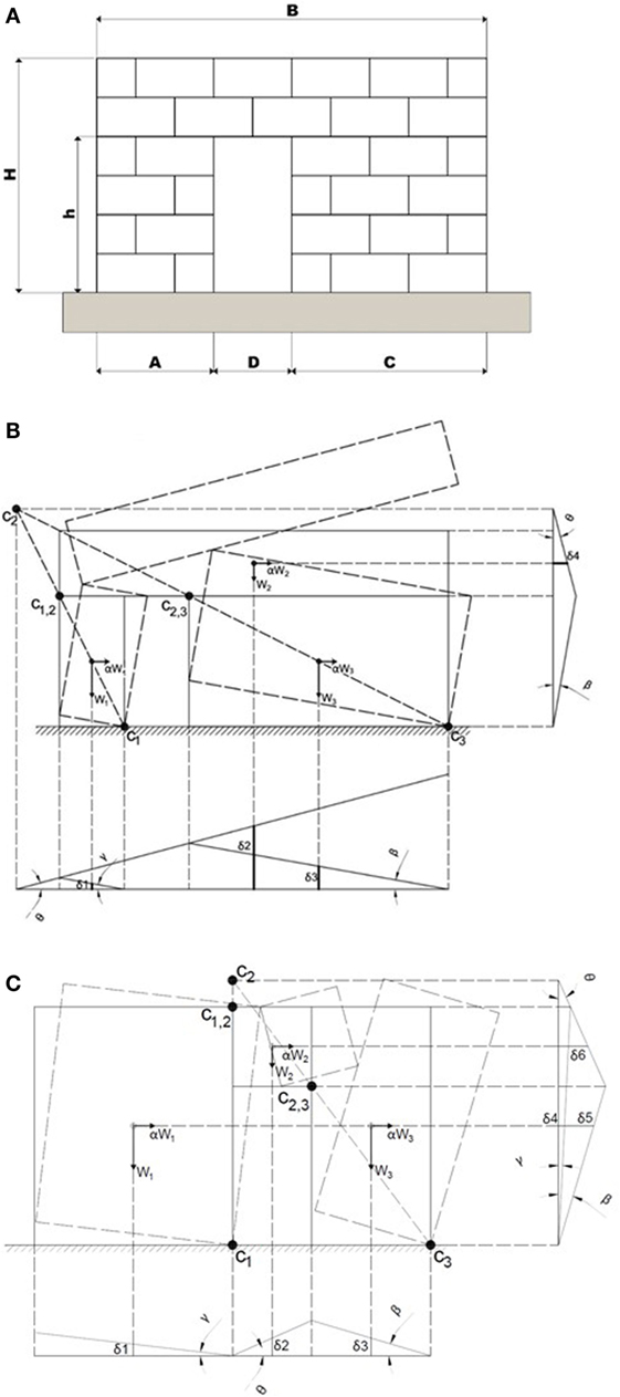
Figure 7. (A) Configuration of a gabion wall with a door opening. (B) Location of hinges for the first selected mechanism. (C) Location of hinges for the second selected mechanism.
Thereby, applying the principle of virtual works for the forces acting on the system, the kinematically admissible multipliers α1 and α2 can be determined as follows:
By considering the dimensions of the 5 m length wall that have been considered in the present study (H = 3 m, B = 5 m, h = 2 m, D = 1 m), the effect of the distance of the opening from the corner (A) on the maximum value of the horizontal acceleration leading to failure is computed. For the considered case study, α1 and α2 may be expressed as function of A and C only (A and C should be expressed in meter):
Table 2 shows the load multipliers α1 and α2 for different values of A and C. Large values are obtained for the load multipliers (minimum value equal to 0.58), indicating that these mechanisms do not represent an issue under the assumptions made and that other failure configurations might be taken into account. Given that the direction of the earthquake horizontal loads cannot be predicted and the system is not symmetric, A and C can replace each other. Consequently, it can be noticed that it is better to use a configuration with door central position (A = C) in order to have better behavior against lateral forces (i.e., largest multiplier equal to 0.70). Note that, in the second mechanism, the two cases corresponding to the first two rows of Table 2 are not physically possible since they would imply compenetration of adjacent rigid blocks that is against the typical assumptions of the kinematic approach. The A and C lengths cannot be lower than 1 m to ensure the cellular behavior of the whole structure and to allow the feasibility of the opening realization.
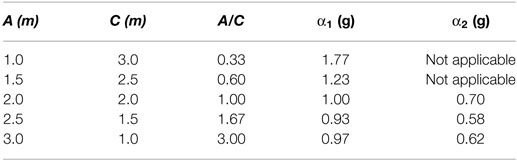
Table 2. α1 and α2 values for different wall configurations.
6. Out-of-Plane Seismic Behavior of a Gabion-Box Wall
In this section, the out-of-plane behavior of a gabion wall under seismic actions is analyzed with reference to the following basic mechanisms:
(1) Cracking of the wall along one horizontal line corresponding to a given interface and associated rigid rotation of the upper wall portion around a horizontal cylindrical hinge (Figure 8A).
(2) Cracking of the wall along three vertical lines (at the two extremities and in the middle section) and associated rigid rotations of the two resulting wall portions around two vertical cylindrical hinges (Figure 8B).
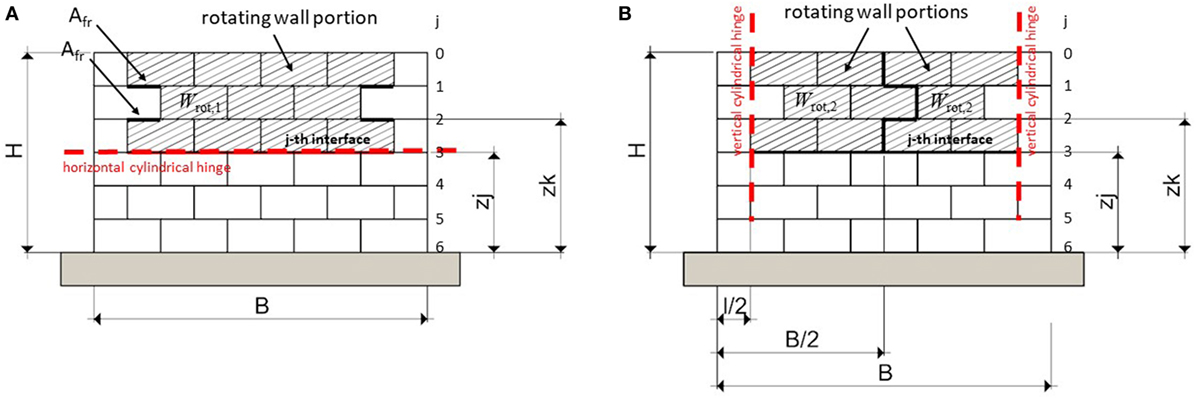
Figure 8. (A) First out-of-plane mechanism. (B) Second out-of-plane mechanism.
6.1. First Out-of-Plane Mechanism
For the first out-of-plane mechanism, the kinematic analysis refers to the hatched wall portion depicted in Figure 8A.
The value of α that triggers the first out-of-plane mechanism at the generic j-th interface can be obtained by imposing the rotational equilibrium:
The destabilising and stabilising moments Mdest,j and Mst,j are evaluated around the horizontal cylindrical hinge formed at the j-th interface and are related to the horizontal inertial force acting on the wall and to the self-weight of the structure (wall + roof) and the side friction forces Ffriction,k, respectively.
The destabilizing overturning moment is:
and the stabilizing moment is:
Wrot,1 is the weight of the wall portion rotating above the j-th interface (hatched in Figure 8A). Ffriction,k represents the total horizontal friction force at the k-th interface at both sides, triggered by the relative motion between the two wall portions:
where . In the present study, Afr = 0.50 m2. The friction forces which could arise along the vertical external interfaces are neglected according to Eq. (2) with σn=0. Also, physical interpenetration of blocks is not taken into consideration.
Equation (13) leads to the following α load multiplier:
Table 3 reports the values of α as function of the position of horizontal cylindrical hinge for the first out-of-plane mechanism. The lowest value of α results around 0.43 for the wall portion rotating around an horizontal cylindrical hinge located at zj = 0.5 m (j = 5). The contribution given by the frictional actions roughly doubles the α value for j = 5, if compared to the α value evaluated without taking into account it, which results equal to the slenderness ratio of the rotating portion of the wall, i.e., .
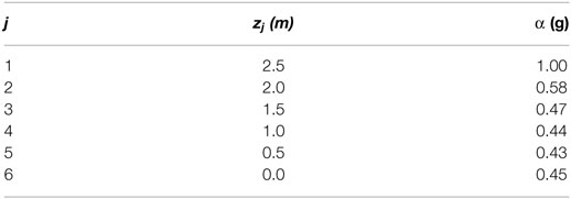
Table 3. Values of α for various locations of the horizontal cylindrical hinge for the first out-of-plane mechanism.
It should be noted that, due to physical interpenetration of the side blocks, only the first two α values associated with rotation around the first and the second interfaces are realistic.
6.2. Second Out-of-Plane Mechanism
For the second out-of-plane mechanism, the kinematic analysis refers to the hatched wall portion depicted in Figure 8B.
The value of α that triggers the second out-of-plane mechanism at the generic j-th interface can be obtained by imposing the rotational equilibrium:
With reference to a single rotating wall portion, the destabilising and stabilising moments Mdest,j and Mst,j are evaluated around the vertical cylindrical hinge formed at the extremity and are related to the horizontal inertial force acting on the wall portion and to the horizontal friction forces acting on the j-th interface, respectively.
The destabilizing moment is:
and the stabilizing moment is:
Wrot,2 is the weight of one single wall portion rotating above the j-th interface (hatched in Figure 8B). Equation 18 leads to the following α load multiplier:
Regardless on the considered j-th interface, in the present study, the value of α results around 0.45. The α value associated with the second out-of-plane mechanism results similar to the α values associated with the first out-of-plane mechanism.
7. Numerical Models
The in-plane and out-of-plane behavior of the gabion-box wall and of half of the one-storey building structure has been also investigated through dynamic analyses by means of Discrete Element Method (DEM).
7.1. DEM Peculiarities
The DEM is characterized by the modeling of the material as an assemblage of distinct blocks interacting along the boundaries (Hart et al., 1988). Therefore, this method is particularly suitable for the analysis of gabion-box wall structures thanks to its capability of allowing large displacements and rotations of discrete bodies. In this study, all the DEM analyses are carried out using the trial version of 3DEC (Itasca Consulting Group Inc, 2013). 3DEC simulates the response of discontinuous bodies subjected to either static or dynamic loading. The discontinuous bodies are represented as an assemblage of discrete blocks. The joints are viewed as interfaces between distinct bodies (i.e., the discontinuity is treated as a boundary condition). Also, the external restraints at the base of the structure (namely unilateral supports acting only in compression) are modeled by similar interfaces. They allow the detachment of the blocks and the automatically detection of new contacts during the calculation progress. The contact forces and displacements at the interfaces of a stressed assembly of blocks are found through a series of calculations, which trace the movements of the blocks. Disturbances caused by applied loads, body forces and contact forces propagate through the block system resulting in displacements of the assemblage.
In the present study, the gabion-box walls are modeled as assemblages of rigid blocks with frictional joints (DeJong, 2009). The joint normal stiffness, kn, and the joint shear stiffness, ks, are defined using the material property of the blocks as following:
where E and G are the Young’s modulus and the shear modulus of the single gabion-box, respectively; ν is the Poisson ratio of the gabion-box; A is the area of the contact (interface) between two adjacent boxes; and ℓ is the length of the rigid material measured along the direction perpendicular to the joint. Table 4 collects the material properties of the gabion boxes. For sake of conciseness, Table 5 collects the properties of each joint on the horizontal and vertical interfaces only for entire gabion-boxes. The roof has been considered as load applied to the walls according to Sections “The Case Study” and “Static Behavior of a Gabion-Box Wall”.
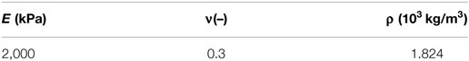
Table 4. Gabion-boxes properties.
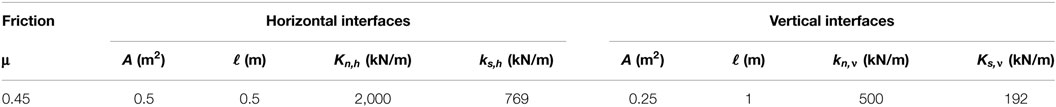
Table 5. Joint properties for entire gabion-boxes.
The input used in the dynamic analyses is the acceleration record of the Kathmandu Valley during the Nepal earthquake of April 25, 2015 (magnitude 7.8) represented in Figure 9.
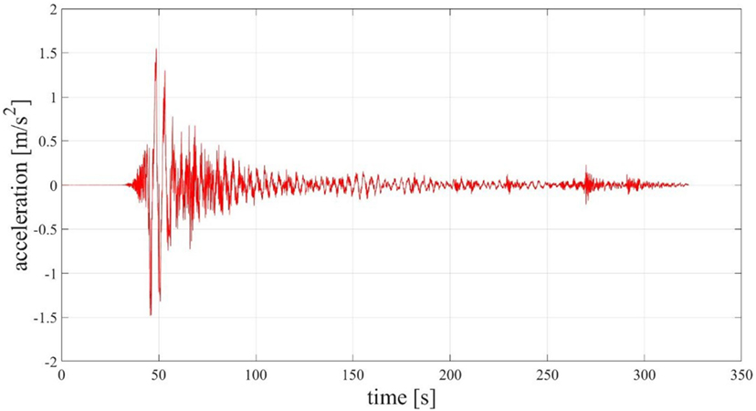
Figure 9. Seismic record used in the analyses.
The response of each gabion-box wall or the whole structure has been investigated by means of a series of dynamic analyses in which the seismic record was gradually scaled until collapse.
7.2. DEM Models for In-Plane Behavior
As far as the in-plane behavior is concerned, the following DEM models have been developed:
• model I1 of the single wall without openings, discretized in six horizontal blocks, for sake of comparison with the results of Section “Sliding Failure of a Gabion Wall without Openings”;
• model I2 of the single wall without openings, discretized in a number of blocks corresponding to the actual number of gabion-boxes to better capture the actual behavior;
• model I3 of the single wall with openings, discretized in three blocks, for sake of comparison with the results of Section “In-Plane Behavior of a Gabion-Box Wall with Openings”;
• model I4 of the single wall with openings, discretized in a number of blocks corresponding to the actual number of gabion-boxes, to better capture the actual behavior.
All next figures present a screenshot of the “just-before-collapse” configuration of the considered DEM models, i.e., the position assumed by the blocks in the time-instant just before collapse due to the scaled seismic record excitation. The displacement values reported in the figures are referred to an inertial reference system and are expressed in meter.
Figure 10 reports the collapse mechanism for model I1, which occurs for a peak ground acceleration around 0.48 g. This is in accordance with the 0.45 g value obtained in Section “Sliding Failure of a Gabion Wall without Openings.”
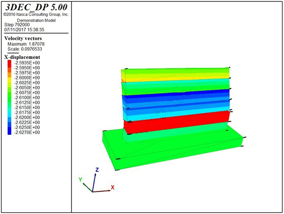
Figure 10. Collapse mechanism for model I1 (activation acceleration = 0.48 g).
Figure 11 reports the collapse mechanism for model I2, which occurs for a PGA around 0.32 g. Thus, the reproduction of the actual number of blocks in the DEM model shows that the failure mechanism changes from a sliding one to a local one associated with the detachment of the upper corner blocks on one side. The capacity is reduced of about 33% with respect to that obtained through a limited number of blocks (model I1).
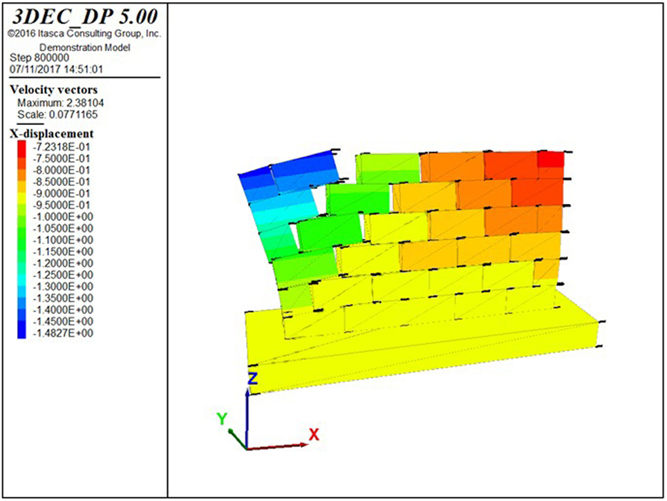
Figure 11. Collapse mechanism for model I2 (activation acceleration = 0.32 g).
Figures 12A,B report the collapse mechanisms for model I3 with openings placed at distances A = 1 m and A = 2 m from the orthogonal wall, which occur for a PGA around 0.53 and 0.48 g, respectively. These results are lower than those obtained with the simplified analytical model discussed in Section “In-Plane Behavior of a Gabion-Box Wall with Openings.” Both cases show a predominant sliding mechanism associated with an incipient out-of-plane mechanism of the upper horizontal block together with a slight rocking mechanism of the two vertical blocks.
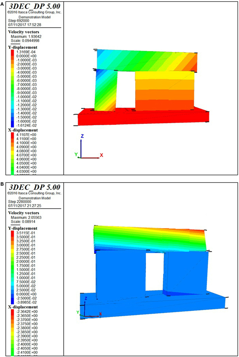
Figure 12. Collapse mechanism for model I3 with (A) A = 1 m (0.53 g) and (B) A = 2 m (0.48 g).
Figures 13A,B report the collapse mechanisms for model I4 with openings placed at distances A = 1 m and A = 2 m from the orthogonal wall, which occur for a PGA around 0.20 and 0.10 g, respectively. Thus, the reproduction of the actual number of blocks in the DEM model shows that the failure mechanisms basically involve the detachment of the blocks just above the door opening. In this respect, it becomes fundamental to insert the timber lintel beams above the opening, which have not been considered in the model. The capacity is strongly reduced, of about 60% and 80% with respect to that obtained through a limited number of blocks (models I3).
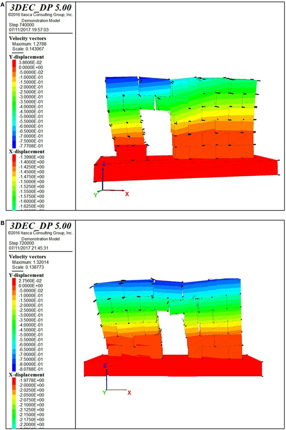
Figure 13. Collapse mechanism for model I4 with (A) A = 1 m (0.20 g) and (B) A = 2 m (0.10 g).
7.3. DEM Models for Out-of-Plane Behavior
As far as the out-of-plane behavior of the single wall is concerned, half of the one-storey building structure has been modeled to take into account the gabion-boxes interlocking in the connections with the two orthogonal walls. The following DEM models have been developed:
• model O1 of the wall under consideration collapsing according to the first out-of-plane mechanism, discretized in two blocks, for sake of comparison with the results of Section “First Out-of-Plane Mechanism”;
• model O2 of the wall under consideration collapsing according to the second out-of-plane mechanism, discretized in three blocks, for sake of comparison with the results of section “Second Out-of-Plane Mechanism”;
• model O3 of half of the one-storey building structure, with the wall under consideration discretized in a number of blocks corresponding to the actual number of gabion-boxes to better capture its actual behavior, and with the two half orthogonal walls each one discretized with six 2.5 m- and 2.0 m-long horizontal blocks, to roughly reproduce the stabilizing effects due to the weight of the orthogonal walls. To take into account the flexibility of the orthogonal walls with a limited number of blocks (trial version of 3DEC), a length of 2.5 m has been assumed instead of the actual 5 m length of the wall.
Figure 14A reports the collapse mechanism for model O1, which occurs for a PGA around 0.2 g. Figure 14B reports the collapse mechanism for model O2, which occurs for a PGA around 0.12 g. In both cases, the DEM models highlight the strong approximation made in the analytical limiting schematizations discussed in Sections “First Out-of-Plane Mechanism” and “Second Out-of-Plane Mechanism.”
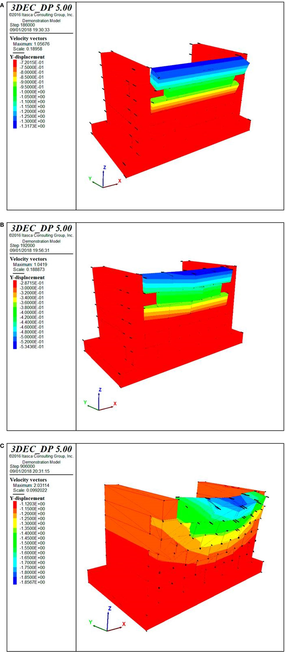
Figure 14. (A) Collapse mechanism for model O1 (0.2 g). (B) Collapse mechanism for model O2 (0.12 g). (C) Collapse mechanism for model O3 (0.15 g).
Figure 14C reports the collapse mechanism for model O3, which occurs for a PGA around 0.15 g. Even though half orthogonal walls have been considered in these DEM models, these preliminary models, characterized by a limited number of blocks, are not capable of fully capturing the cellular behavior which characterizes structures with interlocked connections. For this reason, collapse mechanisms might be activated by slightly larger PGA values.
7.4. DEM Models of the Reinforced Walls
A feasible technique to improve the seismic behavior of a gabion-box wall is represented by the introduction of steel wire knots (Figure 15A) between gabion boxes, which allow to achieve tension strength in the wall. Steel knots are not applied at the basement level, since, due to the absence of foundation, knots cannot be anchored to the soil and the lowest row of gabions still results in simply supported conditions. The effects of the steel wire knots are evaluated by means of DEM models. The steel wire used to tie adjacent gabion boxes together into a knot is assumed to have a diameter equal to 3 mm (the minimum diameter used in El Salvador is 2.2 mm) and a yield stress of about 300 MPa, which, considering shear failure in the knee point of the knot (as per the schematization of Figure 15B, provided that high curvature values do not represent an issue for ductile steel material), lead to a tension strength equal to 2.5 kN per knot (Von Mises, 1913). Thus, considering a spacing of the knots around 20 cm, the additional tension strength to be added in the DEM models is equal to 0.05 MPa.
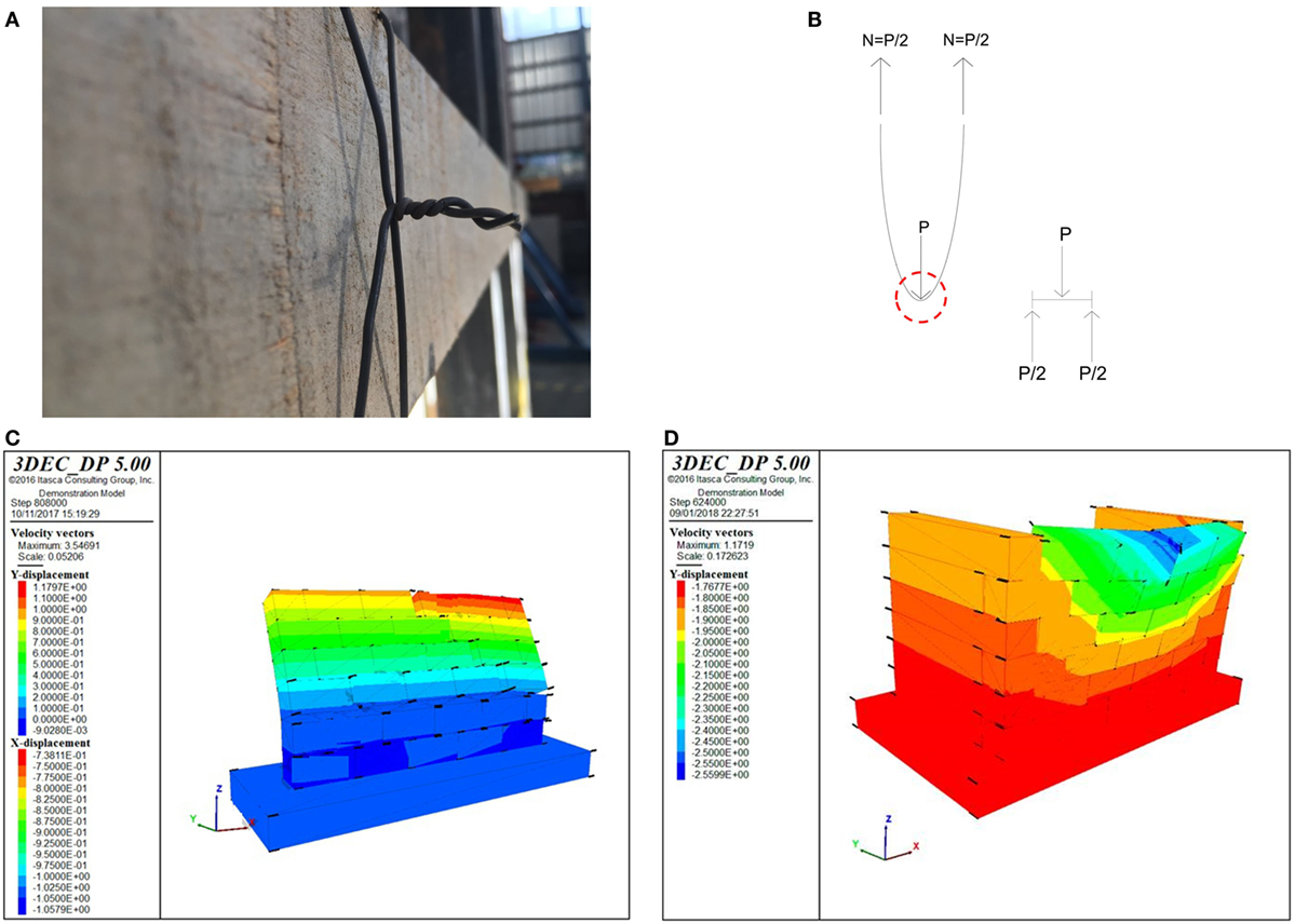
Figure 15. (A) Typical steel wire knot. (B) Knot schematization for strength estimation. (C) Collapse mechanism for model I2-R (0.45 g). (D) Collapse mechanism for model O3-R (0.27 g).
This additional tension strength has been applied only to the models that are characterized by a number of blocks corresponding to the actual number of gabion-boxes, i.e., I2, I4, and O3 models. The reinforced versions of these models are referred to as I2-R, I4-R, and O3-R models.
Figure 15C reports the collapse mechanism for model I2-R, which occurs for a PGA around 0.45 g. Figure 15D reports the collapse mechanism for model O3-R, which occurs for a PGA around 0.27 g. Thus, the insertion of ϕ3 steel wire knots spaced at 20 cm allows to substantially increase the PGA values sustained by the walls: +40% for the in-plane behavior and +80% for the out-of-plane behavior.
The results of the I4-R model do not differ from the ones of the I4 model, since the collapse is still local and involves the detachment of the blocks just above the door opening (the timber lintel beams have not been considered in the model and the added tension strength is locally not enough to prevent that mechanism).
8. Discussion and Rules of Thumb
With reference to the following case study:
1. one-storey gabion-box walls building with bamboo/timber light roof characterized by 5 m × 5 m plan dimensions and 3 m height;
2. dimensions of the gabion-box unit = 0.5 m × 0.5 m × 1 m (w × h × l);
3. dimensions for the door openings = 1 m × 2 m (width × height);
4. dimensions for the window openings = 1 m × 1 m (width × height),
the results obtained allow the following observations:
• the out-of-plane collapse mechanism is characterized by activation acceleration values around 0.15 g;
• the in-plane mechanism activation acceleration depends on the position of the door in the single wall (0.10–0.20 g). The results of the I4 models highlight the absolute necessity of placing timber lintel beams above the openings in order to avoid local detachment of the gabion-box units and to significantly increase the activation accelerations. Moreover, locating the door opening in the middle of the wall leads to horizontal seismic load multiplier slightly higher than those obtained locating the door opening close to one of the orthogonal walls;
• the analytical models developed to capture the out-of-plane response of the single wall are too much approximated and overestimate the seismic capacity of the wall with respect to the results obtained by the DEM models;
• only the analytical model developed to capture the in-plane response of the single full wall with no openings is capable of getting the order of magnitude of the response, thus providing a better agreement with the results obtained by the DEM models;
• reinforcements provided by ϕ3 steel wire knots spaced at 20 cm allow substantial increasing of the seismic capacity of the wall: +40% for the in-plane response and +80% for the out-of-plane response. The lowest activation acceleration value being equal to 0.27 g.
Based on the performed preliminary analyses and the obtained results, the following rules of thumb are proposed in order to achieve a better seismic behavior:
1. Insertion of vertical (steel or timber) connectors or rock elements to provide a cutting strength along the interfaces between adjacent gabion boxes to increase the sliding strength.
2. Locating the window/door opening in the middle of the wall.
3. Two adjacent lines of gabion units above each opening.
4. Two lintel timber beams at least characterized by a 24 cm × 6 cm (width × height) cross section and a length of 3 m above each opening.
5. Reinforcements provided by ϕ3 steel wire knots spaced at 20 cm may allow to achieve seismic activation accelerations around 0.27 g.
6. Steel knots would also be useful to ensure friction between gabion boxes also in the case of vertical ground motions.
To account for possible discrepancies relevant to the material properties, the boundary conditions, the actual geometry and especially the rough modeling (namely, to account for all sources of uncertainties), a global safety factor for design purposes should be introduced at least equal to 2 (for sake of comparison with masonry structures).
However, it should be also pointed out that the typical and strong cellular behavior of a compact one-storey structure characterized by thick interlocked orthogonal walls may considerably increase the seismic activation load multipliers obtained in this research work with reference to precautionary models. The cellular behavior, which has not been fully considered in this preliminary study and which is currently under investigation by means of DEM models of the whole three-dimensional structure, may justify the experimental evidences of gabion-box structures having sustained PGA values larger than 0.3 g in Nepal (www.smartshelterresearch.com).
Finally, it should be clearly stated that the analyses and the results reported in this research work represent a first attempt to face the structural design issues concerning gabion-box wall buildings. This study should be considered as a starting point, in which simple analysis methods for this kind of structures have been proposed, some criticalities have been disclosed and the order of magnitude of the seismic activation load multipliers has been estimated. However, further numerical research as well as experimental tests (especially shaking-table tests) are necessary in order to better understand the global behavior of this kind of structures, particularly with reference to the effectiveness of the cellular behavior.
9. Conclusion
This article represents a first attempt to attack the structural design issues concerning gabion-box wall buildings. A case study has been considered of a one-storey gabion-box walls building with bamboo/timber light roof characterized by 5 m × 5 m plan dimensions and 3 m height. The dimensions of the gabion-box unit are 0.5 m × 0.5 m × 1 m (width × height × length).
The objective of this research work is to give a first insight into the static and seismic behavior of gabion-box walls buildings. The in-plane and out-of-plane seismic responses of the constituting walls have been investigated.
Simple precautionary analytical models, as well as corresponding and refined DEM models have been developed.
Even if this study should be considered as a starting point, the order of magnitude of the seismic activation load multipliers has been estimated, some criticalities have been disclosed, and some rules of thumb have been proposed.
The out-of-plane collapse mechanism is characterized by activation acceleration values around 0.15 g. The in-plane mechanism activation accelerations depend on the position of the door in the single wall and are in the range of 0.10–0.20 g, but placing timber lintel beams above the openings in order to avoid local detachment of the gabion-box units might significantly increase these values. The analytical models developed to capture the out-of-plane response of the single wall are too much approximated, while only the analytical model developed to capture the in-plane response of the single full wall without openings is capable of getting the order of magnitude of the response.
Reinforcements provided by ϕ3 steel wire knots spaced at 20 cm allow substantial increasing of the seismic capacity of the wall, leading to activation accelerations around 0.27 g.
Further numerical research as well as experimental tests (especially shaking-table tests) are necessary in order to better understand the global behavior of the structure and to explore the effectiveness of the cellular behavior.
Author Contributions
This work derives from the main results of the Master graduation thesis of JS, who performed all initial analyses on gabion-box wall structures. LP and SB strongly contributed in the analytical and numerical analyses, respectively. SS supervised both the thesis and this work, identifying the general research lines, and drawing the conclusions.
Conflict of Interest Statement
The authors declare that the research was conducted in the absence of any commercial or financial relationships that could be construed as a potential conflict of interest.
Acknowledgments
The authors are grateful to Martijn Schildkamp of Smart Shelter Research (www.smartshelterresearch.com) for inspiring and stimulating this research work.
References
Agostini, R., Cesario, L., Conte, A., Masetti, M., and Papetti, A. (1987). Flexible Gabion Structures in Earth Retaining Works. Research Report, Bologna: Officine Maccaferri S.p.A.
Al Helo, M. Z., Al-Massri, M. S., Abu-Assi, H. H., Hammouda, M. J., and Joma, I. T. (2016). Experimental Study of Structural Behavior of Mesh-Box Gabion. Gaza, Palestine: Graduation project, Department of Civil Engineering, College of Applied Engineering and Urban Planning, University of Palestine. Available at: http://dspace.up.edu.ps/xmlui/handle/123456789/228
Amato, G., O’Brien, F., Ghosh, B., and Simms, C. (2015). Gabions: evaluation of potential as low-cost roadside barriers. Int. J. Crashworth. 20, 12–26. doi: 10.1080/13588265.2014.949038
DeJong, M. J. (2009). Seismic Assessment Strategies for Masonry Structures. Doctoral dissertation, Massachusetts Institute of Technology, Massachusetts.
European Committee for Standardization. (1998). EN ISO 12944-2: 1998. Paints and Varnishes: Corrosion Protection of Steel Structures by Protective Paint Systems – Part 2: Classification of Environments. Berlin: DIN Deutsches Institut für Normung e.V.
Hart, R., Cundall, P. A., and Lemos, J. (1988). Formulation of a three-dimensional distinct element model-part II. Mechanical calculations for motion and interaction of a system composed of many polyhedral blocks. Int. J. Rock Mech. Min. Sci. 25, 117–125. doi:10.1016/0148-9062(88)92294-2
Heyman, J. (1966). The stone skeleton. Int. J. Solid Struct. 2, 249–279. doi:10.1016/0020-7683(66)90018-7
Jayasree, P. K. (2008). Performance of Gabion Faced Reinforced Earth Retaining Walls. Ph.D. thesis, Division of Civil Engineering, School of Engineering, Cochin University of Science and Technology, Kochi, India. Available at: http://hdl.handle.net/10603/4873
Jiang, Y., and Wang, X. (2011). “Stress-strain behaviour of gabion in compression test and direct shear test,” in Proceedings of the Third International Conference on Transportation Engineering (ICTE) (Chengdu: American Society of Civil Engineers), 1457–1462.
Lin, D. G., Lin, Y. H., and Yu, F. C. (2010a). “Deformation analyses of gabion structures,” in INTERPRAEVENT 2010, Taipei, 512–526.
Lin, Y. L., Yang, G. L., Li, Y., and Zhao, L. H. (2010b). Engineering behaviors of reinforced gabion retaining wall based on laboratory test. J. Cent. South Univ. Technol. 17, 1351–1356. doi:10.1007/s11771-010-0641-y
Ramli, M., Karasu, T., and Dawood, E. T. (2013). The stability of gabion walls for earth retaining structures. Alexandria Eng. J. 52, 705–710. doi:10.1016/j.aej.2013.07.005
Sublette, W. R. (1979). A Behavioral Study of Gabion Retaining Walls. Doctoral dissertation, University of Arizona, Arizona.
Von Mises, R. (1913). Mechanik der festen Körper im plastisch deformablen Zustand. Göttin. Nachr. Math. Phys. 1, 582–592.
Keywords: gabion-box wall, semiengineered building, seismic response, in-plane behavior, out-of-plane behavior
Citation: Samayoa J, Baraccani S, Pieraccini L and Silvestri S (2018) Seismic Behavior of One-Storey Gabion-Box Walls Buildings. Front. Built Environ. 4:7. doi: 10.3389/fbuil.2018.00007
Received: 15 November 2017; Accepted: 23 January 2018;
Published: 21 February 2018
Edited by:
Luigi Di Sarno, University of Sannio, ItalyReviewed by:
Bruno Dal Lago, Politecnico di Milano, ItalyHugo Rodrigues, Polytechnic Institute of Leiria, Portugal
Copyright: © 2018 Samayoa, Baraccani, Pieraccini and Silvestri. This is an open-access article distributed under the terms of the Creative Commons Attribution License (CC BY). The use, distribution or reproduction in other forums is permitted, provided the original author(s) and the copyright owner are credited and that the original publication in this journal is cited, in accordance with accepted academic practice. No use, distribution or reproduction is permitted which does not comply with these terms.
*Correspondence: Stefano Silvestri, stefano.silvestri@unibo.it