DigDesFab15 Research Pavilion
 Andrei Gheorghe1*
 Robert Vierlinger2
- 1Institute of Architecture, University of Applied Arts Vienna, Vienna, Austria
- 2Bollinger + Grohmann, Frankfurt, Germany
This full-scale research pavilion exercises the application of timber and polymer concrete in architectural production (Figure 1). It attempts to develop and test a new hybrid construction technique using composite joints [as introduced in Schober et al. (2014)] within a modular geometric system and no need for formwork. The structure was designed and erected by students and instructors of the Digital Design and Full-Scale Fabrication seminar taught at the Institute of Architecture, University of Applied Arts Vienna. CNC milled, 3-layer spruce laminated timber boards are used for construction, which are temporarily fixed, then rigidized with polymer concrete. The cured composite node proves high structural capabilities, as polymer concrete withstands both pressure and tensile forces, and the bond between the materials is as strong as the wood itself. Compared to traditional timber construction, no metal bolting is needed for the creation of the node, while at the same time, the node geometry becomes more flexible, meaning any three-dimensional layout can be produced, as long as a temporary containment and fixation can be implemented until the chemical curing process is completed (Schober et al., 2016). The geometry is developed as an interpretation of the Zollinger (Menges et al., 2016) grid, where members originally are of twice the grid length (Figure 2) and reciprocally reliant on each other (Figure 3). Instead, every second grid cell is made a joint node when cast out with concrete, making the structural members a lost formwork at the same time (Figure 4). Double-layering each member (see detail explanation of the construction process in Section “Construction Method” below) makes it possible to cast all 122 nodes of the pavilion structure separately and flat-bolt them together on-site with metal screws. Alternative fixation techniques (i.e., glue) of the nodes can be tested in future. The software plugin RhinoVault is used as a design tool to produce an efficient, compression only basic shell surface, although the subsequent imposition of the grid system introduces eccentricities and local imperfections. A parametric model in Rhinoceros and Grasshopper tests various subdivision densities and node sizes and evaluates the overall performance with the structural analysis tool Karamba. The different heights of the lamellas in the structure arise from the analysis and parametric interpretation of stresses under vertical and horizontal loading.
Introduction
This project achieves the construction of a prototypical type of structure (Figure 1) using a new, innovative composite material consisting of wood and polymer concrete. At this level of research, this composite material application is suitable for mid-scale structures (pavilions) with following main features:
1. Prefabrication can be used to a high extent,
2. Structures are lightweight,
3. The creation of structural stiff nodes in wood becomes possible,
4. The composite material allows for an unrestricted geometry (any shape can be produced).
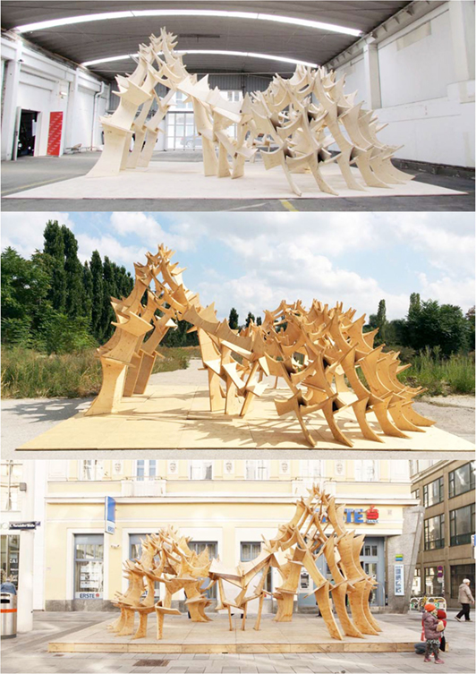
Figure 1. DigDesFab15 “noHOME” research pavilion at multiple locations.
Background
The research pavilion follows a specific structural strategy. It attempts to develop and test a new hybrid construction technique using a combination of polymer concrete and wood as a composite material. Polymer concrete has not yet been tested on large-scale architectural production. The Hochschule Trier completed some full-scale mockups in Trier (2014, 2016) and in Vienna (2014) in cooperation with the University of Applied Arts (Schober et al., 2016). These initial mockups can be inscribed in a bounding box volume of about 3 m × 3 m × 3 m.
In the DigDesFab15 research pavilion project, the polymer concrete material has been tested as a hybrid material in combination and direct adherence with wood boards in a bounding box volume of about 8 m × 8 m × 8 m.
Material Composition and Properties
As opposed to conventional concrete, the binding component of polymer concrete is not cement, but polyester resin. A precise relation and mix of three components is required to ensure the material stiffness. For this project, a total of 120 kg of Epument 140/5 A1 polymer concrete was used. The three necessary components were delivered by the RAMPF Machine Systems GMBH & CO KG company in Wangen bei Göppingen, Germany and were mixed using the ratio shown in the Table 1 below.
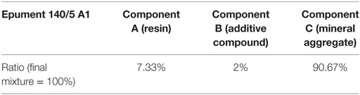
Table 1. Material mixture.
Therefore, due to the exact mixture, no different material consistencies are possible, as this is the case with cement-based concrete. This proves to be a disadvantage when applying and pouring the mixture. Another disadvantage is the delicate handling due to resin-based components and the relatively high price as compared with cement-based concrete.
However, the application of polymer concrete offers also large advantages. The cured material is not brittle, has also high tension (not only compression) abilities, and proves to have a high adherence to wood materials. Esthetically, it can be produced (depending on the additives) with different grain sizes, so that the surface quality can be very smooth or coarse, depending on the formwork surface. Polymer concrete does not need to be compacted by vibration.
Conventional Use of the Material
There is a large palette of applications in the industry for polymer concrete. Polymer concrete is an industrially manufactured material with precise and controllable material qualities such as the grain sizes and stiffness qualities. Because all components (there is no water component) are industrially produced, they can be controlled to a high degree. An important current application of the material is the fabrication of machinery foundations. This is because the guaranteed stiffness is high, the material is not as brittle as normal concrete, and can withstand vibrations and tension forces to a certain degree. See Table 2 below for a comparison of traditional cement-bound concrete and polymer concrete (Institut für Betonbau, 1998; Schober, 2008).
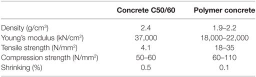
Table 2. Material properties of conventional concrete and polymer concrete (Osman et al., 2012).
Use of the Material in the DigDesFab15 Research Pavilion
In recent years, polymer concrete testing and small-scale applications were conducted at the Hochschule Trier (Prof. W. Becker, Prof. R. Thum) in Germany. The DigDesFab15 project builds upon the knowledge gained through this preliminary research in Germany; however, this type of construction and structural typology has been tested with this research pavilion for the first time at a larger scale. The intention was to create a fully self-supporting structure with structural stiff nodes on a rectangular grid (without the need of using a triangulated grid). This is innovative, because under normal conditions, it is very difficult to achieve structural bending stiff nodes in wood joints; therefore, in many cases, triangulated (truss) systems are used. This problem naturally reduces the availability of cost effective design options for architects and structural engineers.
Methods
Teaching Method
The design process of the research pavilion followed a strict systematic approach. Twenty-four students were organized in four groups of six students each. These groups were given a design task and were tutored toward developing initial design proposals.
The project design was developed from two points of interest. On one hand, the architectural brief asked for an examination to create a light-weight structure, and, on the other hand, a structurally feasible construction technique and application of the polymer concrete in combination with wood had to be developed. It was not required by the architectural brief to design a water-proof shelter for rain protection. The architecture students developed the required Rhino Grasshopper and Karamba analysis setup and definition files with the help of experts from Bollinger + Grohmann Engineers.
Design Method
The structural system has been developed during the design tasks from the so-called Zollinger system (Menges et al., 2016), where small modules (Tamke et al., 2010) are prefabricated and joined to form a greater structure (Sack, 2013). A parametric model in the Rhinoceros and Grasshopper software was created and tested virtually through various subdivision densities and node sizes (Figure 2). The overall structure was evaluated with the structural analysis tool Karamba (plugin for Rhino Grasshopper), the different heights of the lamellas in the pavilion arise from the structural analysis of stresses and deflections under vertical and horizontal loading.
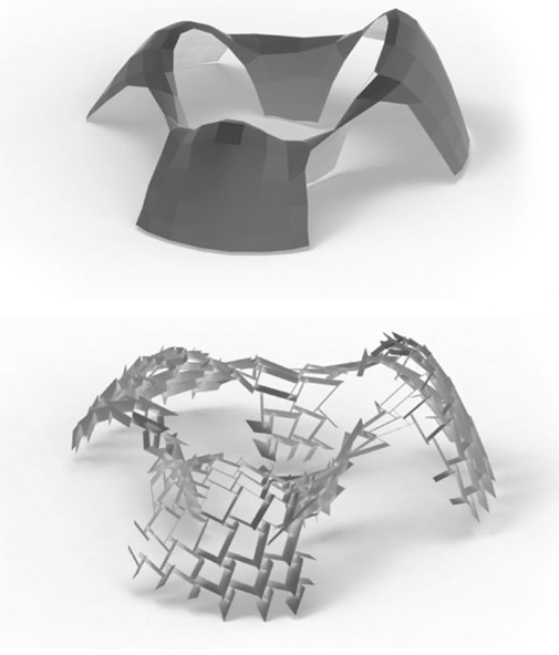
Figure 2. DigDesFab15 “noHOME” research pavilion surface and subdivision strategy.
The Grasshopper definition loads a NURBS surface created in RhinoVault. The definition applies a rectangular subdivision (Figure 3) and creates the corresponding four legs of each node as sheets (or lamellas) of different structural heights. The Karamba plugin is used to apply gravity (vertical) and mesh (horizontal) loads to the structure. The mesh view component and corresponding material utilization results in Karamba is linked to differentiate the height of the lamellas parametrically. The rectangular mesh subdivision is optimized while keeping utilization below 60% of the maximum material capacity.
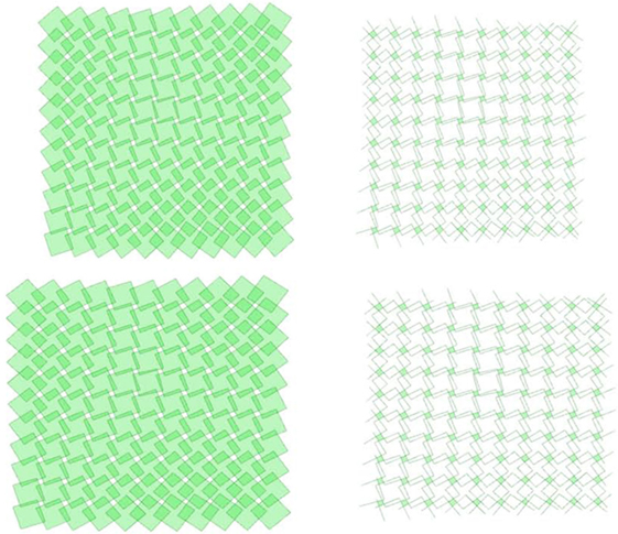
Figure 3. Surface tessellation strategy.
Construction Method
Laminated spruce timber boards (3-layered, 19 mm thick) were used for construction. All the pieces from the 3D model were flattened and distributed on standard size boards (1.25 m × 2.00 m) parametrically, using the Rhino plugin Grasshopper. The pieces were cut by a 3 axe CNC mill (Figure 5), and the edges were sanded to avoid injuries when exhibiting the final piece. The geometrically unique pieces (cut two times for double layering) were labeled in the digital model and the students sorted and labeled and grouped the adjacent pieces (node by node) immediately and manually after production. Each node was screwed together with metal screws as a temporary fixture (Figure 6).
The three-dimensional geometry was predetermined by the shape of the assembled pieces in each node (Figure 4). Neighboring pieces would only fit together on the angles predetermined by the geometry of the milled pieces; therefore, no measurements had to be transferred from the 3D model to the physical model at this state. This means, the four pieces for each node and the bottom sealing plate would fit together only in one way. For helping the assembly process and for purposes of geometry control, marker slits were milled in each piece, indicating where the neighboring piece would need to be attached precisely. The screws only served as a temporary fixation, until the polymer concrete was filled in the center of node for final fixation (Figure 7). Each node was sealed on the bottom with a custom-cut plate out of a thinner (8 mm) plywood material, labeled with a unique code. The project builds up on a rectangular grid, each node has four legs around a central node cavity (reciprocal system) where the polymer concrete was poured (Figure 8). The polymer concrete (curing time about 8 h) adhered with the wood and, therefore, created a structurally stiff node in wood, in a large range of geometrical variations. Normally, it is very difficult to achieve stiff structural nodes in wood structures; therefore, this applied composite method might offer interesting potential in future.
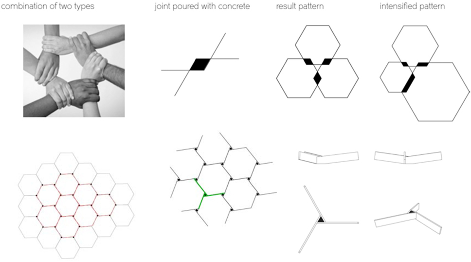
Figure 4. Nodes and concrete casting opportunities.
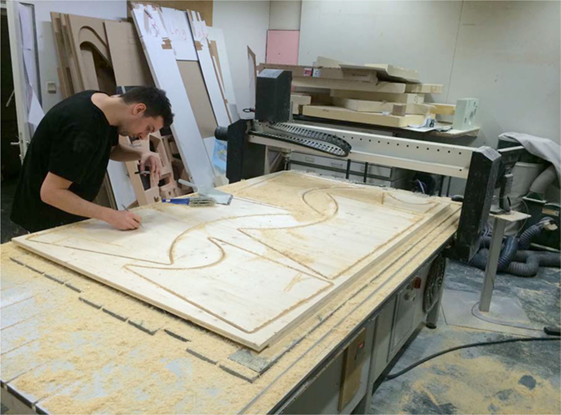
Figure 5. CNC milling.
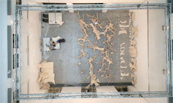
Figure 6. The production pipeline of pre-assembly.
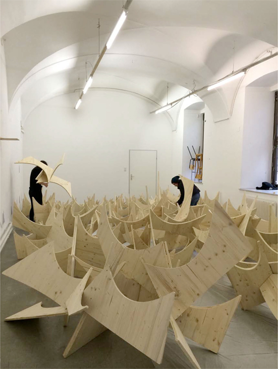
Figure 7. The pre-assembled node modules act as lost formwork.
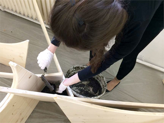
Figure 8. Polymer concrete pouring.
All 122 nodes were cast separately and bolted on-site with screws. An assembly strategy was developed to easily connect the nodes with each other through using milled geometrical references. In the final structure, the wood sheets of the four node legs overlap, so the final material thickness is 2 mm × 19 mm = 38 mm (Figure 11). The overlapping pieces fits at certain positions, this creates a reference when assembling the 1:1 structure. The geometry has been developed with the assistance of the software plugin Rhino Vault to develop a purely compressive load freeform shell. In this case, no supporting formwork (with the exception of the scaffolding for the purposes as described below) was needed for construction, final assembly, and de-construction. The assembly pieces were added starting from the lowest row and the structure reached final structural stability after the arches were completed. During the construction, scaffolding was needed for the assemblers to reach and mount the higher levels of the structure. Equally, the scaffolding helped to stabilize the not completely closed arches of the structure against horizontal loads (wind) during construction.
Results and Reflection
The pavilion was decomposed and re-assembled at different locations. The nodes could be disassembled node after node by unscrewing the connections of the double-layered wood sheets. Measurements were pursued to control the deflection of the physical structure after full loading. These differed (to an extend of <20 mm of local bending in the first row of modules) from the values calculated from the structural Karamba analysis (Figure 9), the largest part of the deformations in the final structure occurred due to imperfections during assembly. These imperfections were further increased after multiple de- and reconstructions (Figure 10). The quality of the hybrid wood board and polymer concrete remained constantly good after being exposed to outside weather and humidity conditions for several months. The wood was not treated in this experiment, in order to not have a potentially structurally weak layer between the wood surface and polymer concrete. Therefore, the exposure of the raw wood to outdoor conditions could not have lasted for more than 6 months. In future experiments, different wood treatments with the combination of polymer concrete application shall be tested. The color of the exposed polymer concrete changed significantly after being exposed to UV light for a longer period. The exposure to outdoor humidity and rain did not negatively affect the structural adherence between wood and concrete, however, due to the fact that the wood surface was not protected, the wood itself showed signs of structural weakening and decomposition. Multiple composite pieces and nodes were tested for material failure, the breaking fissure occurred always within the laminated wood board, and not in the polymer concrete/wood surface joint. Special attention has to be devoted to following practical problem during construction: due to the fact that the polymer concrete has to be poured and (and the material consistency of the polymer concrete cannot be changed), solutions have to be found for keeping the fluid polymer concrete in contact with the wood until curing (formwork, temporary fixation, etc.).
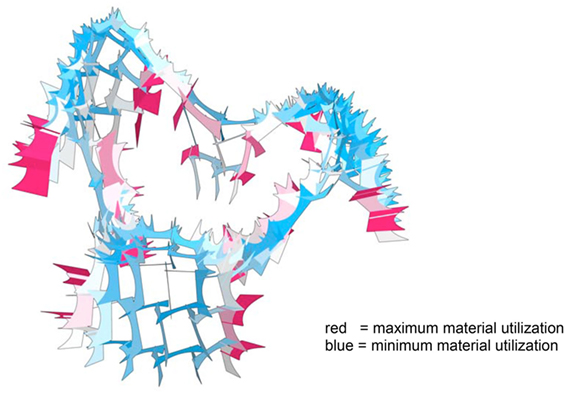
Figure 9. Structural analysis in Karamba—utilization of elements (red = max, blue = min), after which the depth has been scaled in the parametric setup.
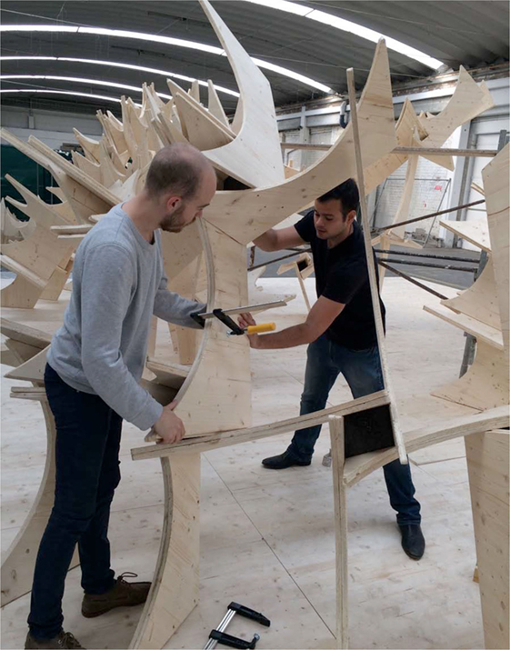
Figure 10. Pavilion assembly by bolting the modules to double layers.
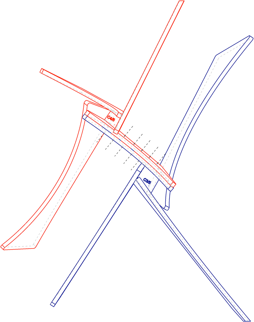
Figure 11. Double-layering principle: overlapping wood sheet between nodes C3/5 and C4/5 with axis of screws connection (five per side).
Conclusion
Due to the experimental nature of this project, it was very helpful to develop and test the underlying basic principles within an academic setting. The students benefited from the collaboration with structural experts and became used to the simultaneous development and combination of design expertise and technological or structural principles. At the same time, the considerably amount of work involved in designing, manufacturing, and assembling the prototypical structure for testing purposes only would not have been possible in a purely industrial setting without investing substantial financial and human resources.
This construction technique proved to be a structurally viable way to produce stiff timber nodes in any geometrical layout for mid-scale outdoor construction within this specific structural system. Normally, for structural stiff wood/wood connections, steel inlays or special screws/bolted connections are required. For this research project, the wood pieces were connected in a stiff structural node by pouring polymer concrete. If the contact surface between polymer concrete and wood is large enough, the hybrid polymer concrete/wood joint can be exposed to high tension and compression forces before material failure happens. Usually, the adherence is high; therefore, the material failure occurs in the wood component, without destroying the composite joint. No other materials have been tested for this project; however, further research might incorporate the use of other flat materials, such as aluminum composite boards (Alucobond) as an alternative to wood sheets. With this technique, no steel inlays are needed to create stiff wood/wood connections. One of the largest advantage of this composite construction technique is that due to the fluid material consistency of the polymer concrete, any geometrical, three-dimensional layout can be produced, as long as a temporary containment and fixation can be implemented until the chemical curing process is completed (about 8 h). The composite material testing at middle scale (pavilion scale) has been successful, however, for large scale, industrial architectural application at building scale, further knowledge and research has to be done specifically in two areas:
A. Assessing structural strengths (compressions/tension ability) of the composite material
B. Long-term durability (exposure to humidity and UV light) of the composite material.
Author Contributions
AG was the project leader and responsible for the research project. RV supported the parametric design process and provided structural design expert knowledge (Grasshopper, Karamba).
Conflict of Interest Statement
The authors declare that the research was conducted in the absence of any commercial or financial relationships that could be construed as a potential conflict of interest.
Acknowledgments
Special Thanks to: University of Applied Arts Vienna/Institute of Architecture Bollinger + Grohmann Ingenieure Loftcity Brotfabrik Wien Hochschule Trier Rampf Group and to all involved students.
References
Menges, A., Schwinn, T., and Krieg, O.D. (2016). Advancing Wood Architecture: A Computational Approach. London: Taylor & Francis Ltd.
Osman, G., Witold, B., Gonzalo, M., and Mustafa Sabri, G. (2012). Mechanical properties of polymer concretes containing different amount of hematite or colemanite. POLIMERY 57: 276–82. Available at: https://lapom.unt.edu/publications/pdf%20articles/Kai/04_gencel.pdf
Sack, F. (2013). MIKADOWeb. In Design Modelling Symposium, Proceedings of the Design Modeling Symposium (Poster Session), Berlin.
Schober, K. U. (2008). Untersuchungen zum Tragverhalten hybrider Verbundkonstruktionen aus Polymerbeton, faserverstärkten Kunststoffen und Holz. Thesis, IKI, Bauhaus Universität Weimar.
Schober, K.U., Becker, W., Drass, M., and Weber, J. (2014). High-performance timber composite joints for spatial round wood truss structures. In Proceedings of the 13th World Conference on Timber Engineering (Wcte 2014), Quebec, QC.
Schober, K.U., Becker, W., and Weber, J. (2016). Grouted joints in timber engineering. In Proceedings of the 16th World Conference on Timber Engineering (WCTE 2016), Vienna, Austria.
Keywords: digital architectural design, parametric design, digital fabrication, polymer concrete construction, reciprocal structure
Citation: Gheorghe A and Vierlinger R (2017) DigDesFab15 Research Pavilion. Front. Digit. Humanit. 4:18. doi: 10.3389/fdigh.2017.00018
Received: 23 September 2016; Accepted: 12 September 2017;
Published: 27 September 2017
Edited by:
Michael Budig, Singapore University of Technology and Design, SingaporeReviewed by:
Sam Jacoby, Architectural Association School of Architecture, United KingdomGabriela Celani, Universidade Estadual de Campinas, Brazil
Copyright: © 2017 Gheorghe and Vierlinger. This is an open-access article distributed under the terms of the Creative Commons Attribution License (CC BY). The use, distribution or reproduction in other forums is permitted, provided the original author(s) or licensor are credited and that the original publication in this journal is cited, in accordance with accepted academic practice. No use, distribution or reproduction is permitted which does not comply with these terms.
*Correspondence: Andrei Gheorghe, a.gheorghe@uni-ak.ac.at