Dynamic feeder dyke systems in basaltic volcanoes: the exceptional example of the 1809 Etna eruption (Italy)
 Nobuo Geshi
 Marco Neri
- 1AIST, Geological Survey Japan, Tsukuba, Japan
- 2Istituto Nazionale di Geofisica e Vulcanologia, Sezione di Catania, Osservatorio Etneo, Catania, Italy
The detection and understanding of the movement of magma at very shallow levels remains one of the most fascinating challenges of modern volcanology, because such information allows us to identify and circumscribe the most probable location where future eruptive vents will open. Unfortunately, it is rarely possible to observe any detail of the internal structure of the feeder system of recent eruptions; in only very few cases, geological observations in dissected volcanoes can help us imagine how magma moved and evolved inside the feeder system. In this paper, we describe the 1809 eruption of Mt. Etna, Italy, which represents one historical and rare case in which it is possible to closely observe the internal structure of the feeder system. This is possible thanks to the presence of two large pit craters located in the middle of the eruptive fracture field that allow studying a section of the shallow feeder system. Along the walls of one of these craters, we analyzed well–exposed cross sections of the uppermost 15–20 m of the feeder system and related volcanic products. Here, we describe the structure, morphology and lithology of this portion of the 1809 feeder system, including the host rock which conditioned the propagation of the dyke, and compare the results with other recent eruptions. Finally, we propose a dynamic model of the magma behavior inside a laterally–propagating feeder dyke, demonstrating how this dynamic triggered important changes in the eruptive style (from effusive/Strombolian to phreatomagmatic) during the same eruption. This is therefore an exceptional case to understand how basaltic magmas move during the propagation of an eruptive fissure, which furnishes fundamental elements for the modeling of superficial intrusive processes. Our results are also useful for hazard assessment related to the development of flank eruptions, potentially the most hazardous type of eruption from basaltic volcanoes in densely urbanized areas.
Introduction
Lateral eruptions are potentially one of the most dangerous types of eruption especially in densely–urbanized contexts, since the rapid propagation of a dyke in the volcano flanks can feed lavas in the lower slopes in a very short time (Gudmundsson, 1987; Rubin and Pollard, 1987; McGuire and Pullen, 1989; Gudmundsson et al., 1992; Komorowski et al., 2002; Acocella and Neri, 2003; Acocella et al., 2006a,b). The style of flank eruption can change rapidly as the magma feeding system evolves with the propagation of a feeder dyke (Bousquet and Lanzafame, 2001; Tedesco et al., 2007; Neri et al., 2008, 2011; Soriano et al., 2008). Many factors, including changes in the dyke size, temporal variations in the magma flux, progress of vesiculation, fragmentation, drain–back, erosion of the conduit walls and hydromagmatic interaction, can all affect the evolution of the eruption style. These factors may also interact with each other during the evolution of an eruption. Comparison between these processes in a feeder dyke and the evolution of the eruption at the surface is therefore fundamental to understand the role played by dykes during flank eruptions.
Even if it is impossible to directly observe details of the internal structure of the feeder system during an eruption, geological observations in dissected volcanoes can provide insights into the structure of shallow feeder systems (e.g., Acocella et al., 2006a, 2009; Keating et al., 2008; Geshi et al., 2010; Geshi and Oikawa, 2014). The links between the underground plumbing system and volcanic activity can be ascertained through a combined analysis of historical eruptions, eruptive products and structure of the feeder systems. Unfortunately, there are few examples of the outcropping feeder systems that preserve both the feeder dyke and its eruptive products of historical eruptions (e.g., the feeder of the 1983 eruption of Miyakejima; Wada, 1992).
Here, we present one good example of well–exposed cross sections, namely from the 1809 eruptive fissure at Mt. Etna, Italy (Figure 1) along the crater walls of two pit–craters in the NE Rift zone of the volcano. The outcrops show the cross sections of the uppermost 15–20 m of the explosive vents, along the central portion of the eruptive fissure system. We describe the structure of the shallow feeder system of this eruption, comparing it with the historical record of other recent eruptions, and propose a dynamic model of the magma behavior inside a laterally–propagating feeder dyke. The overall aim of the paper is to demonstrate the influence of magma dynamics inside fractures on the evolving eruptive behavior, also with a view toward hazard assessment.
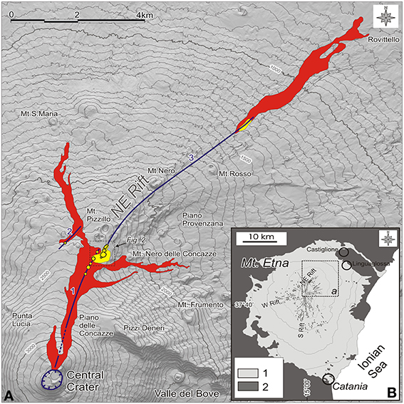
Figure 1. Map of the 1809 eruption, which affected the NE Rift of Mt. Etna volcano (modified after Gemmellaro, 1860; Garduño et al., 1997; Branca et al., 2011). Most portions of the higher (between 3300 and 2500m asl) and lower (between 1300 and 750m asl) lava flows are today buried by younger volcanic products. (A) The lava flows are shown in red. The eruptive fissures are indicated in blue and numbered 1 to 3 from top to bottom, according to the chronology of opening. Yellow areas highlight the main cinder cones and explosive vents (see text for details). Contour lines are in metres. (B) The main rift zones of Etna and the location of the studied area. 1. volcanics; 2. sedimentary basement.
Geological Setting
Mt. Etna is the highest active volcano in Europe (3329 m above sea level—asl. Figure 1) located on the eastern coast of Sicily. It began to be active ~500 ka on the front of the Apennine–Maghrebian Chain, and lies on clayish–sandy Pliocene–Pleistocene foredeep deposits (Lanzafame et al., 1997; Branca et al., 2011, and references therein).
Etna today has a central conduit that feeds four summit craters named Voragine (VOR; formed in 1945 inside the former Central Crater), Northeast Crater (NEC; 1911), Bocca Nuova (BN; 1968) and Southeast Crater (SEC; 1971); the latter has been the most active in recent decades with the growth of a huge new cone on its southeast flank, named the New Southeast Crater (NSEC; 2007; Del Negro et al., 2013). Volcanic events from any of these summit craters are known as summit eruptions (Acocella and Neri, 2003, and references therein).
Flank eruptions occur along radial fissures centered on three main “rift zones”: the NE Rift, the S Rift and the W Rift (Figure 1B; Acocella and Neri, 2003; Cappello et al., 2012). These eruptions are fed by shallow (1–3 km) dykes, which start from the central conduit and propagate laterally into the rift zones (Rubin and Pollard, 1987; Neri et al., 2011). A second, much less frequent type of flank eruption is triggered by magmatic intrusions directly fed by the reservoir beneath the volcano and named “eccentric” or “peripheral” eruptions (Acocella and Neri, 2003), since they are independent of the central conduit.
Summit activity is almost continuous, while flank eruptions occur at irregular intervals though, during the last 130 years, they seem to take place in cycles lasting one or two decades (Behncke and Neri, 2003a; Allard et al., 2006).
The NE Rift is a network of N– to NE–striking, closely spaced, subparallel eruptive fractures extending from the NEC to the Mt. Rosso area at ~1400 m asl. The Rift is 0.5 km wide and more than 7 km long (Figure 1). The NE Rift is also the NW margin of a wide sector of Mt. Etna involved in seaward displacement (Ruch et al., 2010, 2013; Solaro et al., 2010 and references therein), affecting an onshore area of >700 km2 (Neri et al., 2004) and a thickness of 1–4 km (Siniscalchi et al., 2012). During the last 110 years, the NE Rift eruptions lasted 21 days on average, with 7 m3s−1 eruption rates. The eruptive fissures propagated at an average speed of 0.053 ms−1, reaching the a maximum length (3825 m) in ~1 day (Neri et al., 2011).
The possible relationship between flank deformation and eruptive activity has recently been highlighted by several authors, i.e., acceleration of flank deformation may trigger flank eruptions and vice versa (Acocella et al., 2003; Neri and Acocella, 2006; Bonforte et al., 2011; Ruch et al., 2012, and references therein), and both (during the last century) are concentrated in time intervals lasting 10–20 years (Behncke and Neri, 2003a; Allard et al., 2006).
Chronology of the 1809 Eruption
The 1809 eruption was one of the major flank eruptions of Etna during the 19th Century. It was characterized by earthquake swarms, exceptionally long and fast eruptive fissures and highly fed lava flows. The inhabitants on the northern side of the volcano were considerably troubled by the eruption, especially on witnessing large areas of the territory invaded by lava (Gemmellaro, 1860).
A few days before the onset of the eruption, the Central Crater was very active (Figure 1A). It was characterized by Strombolian activity coupled with intense and abundant ash emissions. This activity was also accompanied by strong earthquakes that were felt in particular in the northern sector of the volcano, between the villages of Castiglione and Linguaglossa.
The seismic swarms intensified until the opening of the first NNE–aligned eruptive fissure (Fissure “1” in Figure 1A), located on the northern side of the Central Crater (> 3200 m asl), on 27 March 1809. From this first fissure a lava flow emerged and began to spread over the high northern flank of the volcano. In the following hours, the fracture field propagated rapidly along the high part of the NE Rift, accompanied by intense seismic swarms. On the morning of March 28, it reached the area of Mt. Pizzillo (2350 m asl, Figure 1A), extending for a length of ~4250 m. The width of the fracture field ranged between 200 and 1100 m, from the top down.
Between 10.00 and 18.00 on March 28, the lower portion of the fracture field became eruptive, forming several explosive and effusive vents; the lava flows erupted mainly from two fissures, one located on the eastern edge of the NE Rift, while a smaller eruptive fissure (about 1200 m long) opened on the opposite side of the rift, west of Mt. Pizzillo (Fissure “2” in Figure 1A). Consequently, the lavas expanded in two distinct directions: the lava flow erupted from Fissure “1,” descended along the northern slope of the volcano and remained active for about four days, reaching a maximum length of ~5500 m and a minimum altitude of 1710 m asl, just above Mt. S. Maria (Figure 1A). A second lava flow expanded eastward, approached the southern slope of Mt. Nero delle Concazze and halted at an altitude of 1800 m asl, reaching a maximum length of about ~2900 m (Figure 1A).
On March 29, the fracture field propagated abruptly further down, rotating approximately 15° to the East and following the alignment of the lower portion of the NE Rift (Fissure “3” in Figure 1A). An additional 18 vents formed on Fissure 3, which expelled dense clouds of gas and ash violently, though without erupting lava flows. At ~21.00 the same day, this fracture reached 1400 m asl, covering a distance of more than 5500 m from the craters “A” and “B” located near Mt Pizzillo (Figure 2). Along the lower segment of the fracture field, between 1450 and 1325 m asl, five new eruptive vents opened that fed lavas flowing toward the northeast. These lava flows remained active until April 9 and reached the minimum elevation of 670 m asl, having covered a distance of ~5500 m.
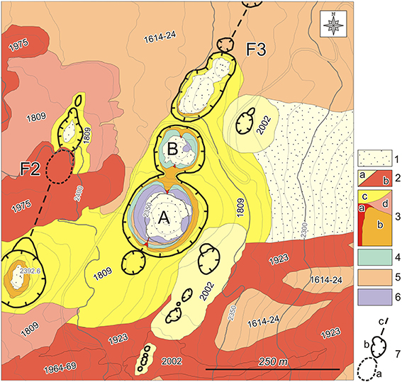
Figure 2. Geological map of the central portion of the 1809 volcanics and structures, between 2440 and 2260 m asl. The 1809 lavas and pyroclasts are partially buried by younger volcanics. (A,B) are the main craters described in the text. Unit 1. talus deposit; Unit 2. post–1960 lavas (a) and cinder cones (b), dates indicate the age of the eruption; Unit 3. Volcanic products of the 1809 eruption, analyzed in the present paper: dykes (a), cinder cones (b), lithic material erupted by phreatomagmatic (Surtseyan) activity (c), lava flows (d); Unit 4. cinder cone of unknown age (between 1624 and 1809); Unit 5. 1614–1624 lava flows; Unit 6. Volcanics belonging to the Ellittico volcanic center (~15 ka). 7. Eruptive fissures: buried craters (a), outcropping craters (b), dry and/or buried fractures (c). Note the en–echelon arrangement of the lower portion of fissure F2 (left) and the higher portion of fissure F3 (right), as indicated in Figure 1.
Field Observations of the Feeders of the 1809 Eruption
In this section, we describe our methodological approach, which is mainly based on the structural mapping of the area, and the results. We analyze in detail the 1809 feeder system and the host rock lithology. Then we distinguish the main lithological facies, the structure and size of the feeder system, and the eruptive mechanisms related to the feeder.
Description of the Outcrop
Today, we can observe the 1809 feeder system in four outcrops exposed along the walls of two adjacent craters (A and B in Figure 2), that were formed during the later stage of the eruption. Hereafter, we identify the outcrops of the feeder system as A–S at the southern wall of the crater A, A–N at the northern wall of the crater A, B–S at the southern wall of the crater B, and B–N at the northern wall of the crater B, respectively. The most important and clear outcrops are inside crater A and for this reason we focus particularly on the description of this crater. Only the uppermost part of the feeder system is exposed in crater B.
Craters A and B are located along the uppermost part of the eruptive Fissure 3 (Figures 1A, 2). These two craters and other small ones form a ~450 m long segment of the eruptive fissure that still crops out (although partially buried by younger volcanic products), between 2390 and 2340 m asl (Figure 2). The outcrop A–N is at the center of this segment and A–S is at the peripheral part, ~150 m from the center. The alignment of the craters indicates that the strike of the feeder dyke is 020°, parallel to the strike of the central portion of the NE Rift (Figures 1,2). We should define some key terms used in this paper to avoid any confusion. A “feeder system” connects to a vent and includes the entire magma plumbing system below the original ground surface. The term “dyke” is used only for a vertical intrusive body that fills a fracture in the host rock.
Host rock lithology
The walls of crater A and B consist of four different layers of volcanic rocks (Units 3, 4, 5, and 6) described in the following paragraphs (see Figures 2, 3). Unit 3 relates to the product of the 1809 eruption. The basement of Unit 3, namely the original ground surface before the 1809 eruption, is inclined ~15 degrees eastward.
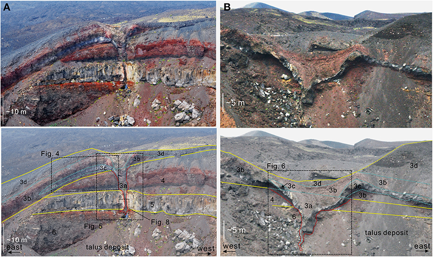
Figure 3. Outcrops of the feeder system of the 1809 eruption along the walls of the crater A (see Figure 2 for location). (A) Southern wall (A–S); (B) northern wall (A–N). The two pictures at bottom illustrate the stratigraphic interpretation. The names of geological units are the same as Figure 2. The host rock of the feeder system is marked with red lines. Yellow lines show the unit boundaries. Blue lines are sub–boundaries inside the same unit. Boxes with dashed lines show the areas in Figures 4–6 and 8.
The host rocks of the feeder system are made up of three different layers of volcanic rocks of varying age (Units 4, 5, and 6, from top to the bottom; Figure 3). All these units are exposed in the outcrop A–S, while Unit 4 is not exposed in the outcrop A–N and in crater B.
Unit 4 is made up of a partially welded pile of spatters (Figure 3A). The maximum thickness (~7 m) is at the southern wall of the crater A, and decreases to zero toward the East (Figure 4). In crater B, this unit crops out nearly continuously along its walls. Unit 4 consists of a pile of basaltic scoriaceous bombs up to 0.5 m in diameter, dark–reddish in color due to oxidation and partly welded to each other. At the top, Unit 4 is made up of a volcanic ash layer of 0–0.5 m thickness (Unit 4′ in Figure 4). The age of Unit 4 is not identified; most likely it belongs to an eruption occurring between 1624 and 1809, judging from its position in the stratigraphic succession of the area.
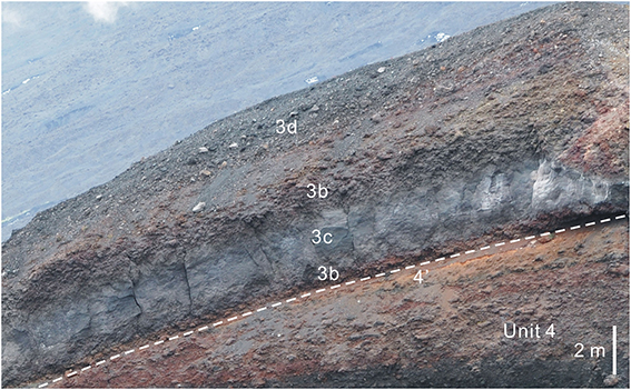
Figure 4. Proximal deposit of the 1809 eruption (Unit 3) at the southern wall of crater A. White dashed line shows the base of Unit 3b, which is the original ground surface before the 1809 eruption.
A massive lava flow (Unit 5) is located under Unit 4 and the contact between the two units is erosive (Figures 3, 5). Distribution of Unit 5 is limited to the southern half of the crater A, where the thickness is ~7 m. It consists of a coherent central part (maximum thickness of ~5 m), bounded by basal and top clinker layers. Semi–vertical joints develop sparsely in the central massive part. The thickness of clinker layers is ~0.5 m at the base and ~1 m at the top. At the top, the lava flow is covered by an unconsolidated volcanic ash layer (~0.8 m thick; Unit 5′ in Figure 5). Distribution of Unit 5 implies that it corresponds to the lava flow of the 1614–1624 eruption.
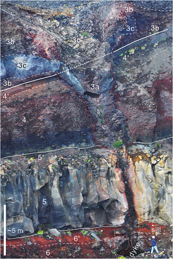
Figure 5. Close-up view of the feeder system on the southern wall of the 1809 crater A (outcrop A–S). The outlines of the feeder system are highlighted with red lines. White solid lines show the unit boundary. Dashed lines show the sub–boundary in each unit. Boundary between Units 3b and 4 represents the ground surface at the beginning of the 1809 eruption. See text for lithological details.
An erosional contact separates the lavas belonging to Unit 5 and the underlying Unit 6 that corresponds to the deeper and older stratigraphic layer cropping out in the craters A and B. This deeper unit consists of a partially welded pile of spatters and scoriaceous bombs up to 0.5 m in diameter, which probably belongs to the younger eruptive products of Ellittico (~15 ka; Garduño et al., 1997). The thickness of Unit 6 is more than 10 m, though the bottom is not exposed. The top of Unit 6 is made up of a layer of unconsolidated volcanic ash (~1 m thick; Unit 6′ in Figure 5), reddish in color due to the thermal metamorphism induced by the overlying Unit 5.
Ejecta from the feeder system
Unit 3 is the eruptive product of the 1809 eruption and forms a cinder cone around the craters. It is subdivided into four parts: 3a, 3b, 3c, and 3d, each of them characterized by different structure and lithology (Figures 4–7).
Unit 3a is the vent–fill deposit distributing inside the feeder system (Figures 5, 6). It consists of coherent basaltic lava at the margin and unconsolidated scoriaceous breccia at the central portion of the vent.
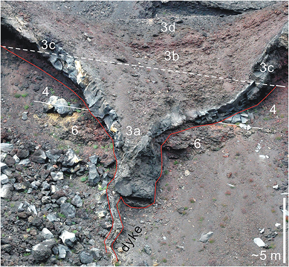
Figure 6. Close-up view of the feeder system on the northern wall of the 1809 crater A (outcrop A–N). The outlines of the feeder system are highlighted with red lines. White solid lines show the unit boundaries. The dashed line represents the ground surface at the beginning of the 1809 eruption. See text for lithological details.
Units 3b, 3c, and 3d are the fall–out deposits surrounding the craters A and B (Figures 2, 4, 5). Units 3b and 3c consist of basaltic bombs and welded breccia and occupy the lower half of the deposit. Unit 3d is characterized by abundant lithic blocks and consists of the upper half of the deposit.
In detail, Unit 3b and 3c consist of a pile of juvenile bombs and contain very small amounts of lithic fragments. Unit 3b is made up of unconsolidated—weakly consolidated breccia, while Unit 3c is a welded breccia. The boundary between 3b and 3c is gradual and Unit 3c is enclosed by 3b (Figure 4). The deposit of Unit 3b is well–sorted and lacks the fine–grained component. The bombs have a reddish color due to oxidation; their prevailing size is 0.2–0.5 m in diameter. Well defined basaltic bombs are difficult to identify in Unit 3c owing to strong welding.
Unit 3d consists of a lithic–rich volcanic breccia with a small amount of basaltic spatter. The maximum size of lithic fragments is 0.5 m. This deposit is unsorted and unconsolidated and exhibits no evidence of welding. It contains volcanic sand–ash. Unit 3d overlies Unit 3b. The boundary between Unit 3d and the underlying 3b is gradual.
Distribution of these fall–out deposits (Units 3b, 3c, and 3d) is asymmetric, probably due to the oblique ejection. The thickness of Unit 3b and 3c in the lower half of the deposit is greatest at the eastern rim of the crater A, ~100 m from the feeder, whereas Unit 3b decreases to zero ~20 m west of the eruption site, in both the craters A and B. Even if Unit 3d covers the entire crater rim, the thickness is greater in the eastern rim (~30 m) and thinner in the western rim (<2 m).
Structure of the Feeder System
The cross section of the feeder system of the 1809 eruption, consisting of a feeder dyke and a sill in the lowest portion, the diatreme, crater and the scoria cone, is well–exposed only on the walls of crater A (Figure 3). The exposure of the feeder system in crater B is limited only to the diatreme part owing to the development of the talus deposit.
In the outcrop A–S, the feeder system up to 22 m deep from the existing, original ground surface before the 1809 eruption (bottom of Unit 3b) is exposed (Figure 5). The feeder system is divided in three portions: the deeper part consists of a dyke cropping out >16 m below the ground. Between 16 and 15 m in depth, the feeder forms a horizontal intrusion (hereafter “sill”) in Unit 6', immediately under the base of overlying Unit 5. The shallower part of the feeder system is made up of an upward–flaring diatreme. The feeder system is almost vertical at depths greater than 15 m from the original surface. It inclines~75° westward within the uppermost 15 m, and is perpendicular to the original ground surface (the base of Unit 3b inclined ~15°eastward; see Figures 3, 5).
In the outcrop A–N, the feeder system exposes its uppermost 15 m (Figure 6). The feeder system shifts from a dyke around 15 m deep to an upward–flaring diatreme. The feeder system inclines ~75 degrees westward, and is perpendicular to the original ground surface (the base of Unit 3b inclined ~15 degrees eastward).
In the outcrop B–S, the feeder system exposes its uppermost 7–8 m, in which the feeder system shows an upward–flaring diatreme. No feeder dyke is exposed. At the base of the outcrop, the width of the feeder is 16 m and increases to 30 m at the base of Unit 3.
The uppermost 15 m of the feeder system is exposed in the outcrop B–N. The whole feeder system in this outcrop is made of the diatreme and no feeder dyke is exposed. The width of the feeder system at the bottom of the outcrop is 3.6 m and the width increases to 22 m at the base of Unit 3.
The thickness of the feeder system depends on the host rock lithology (Figure 7). The feeder in the outcrop A–S has an almost constant thickness (0.2 m) in the central part of Unit 6. The thickness increases to 0.6 m in the volcanic ash layer at the top of Unit 6, and then converts to a 4 m width sill. The feeder intrudes in Unit 5 with almost constant thickness of 0.75 m. The feeder flares toward the original ground surface in Unit 4. The thickness of the feeder increases from 2 m at the base of Unit 4 to 13 m at the original ground surface.
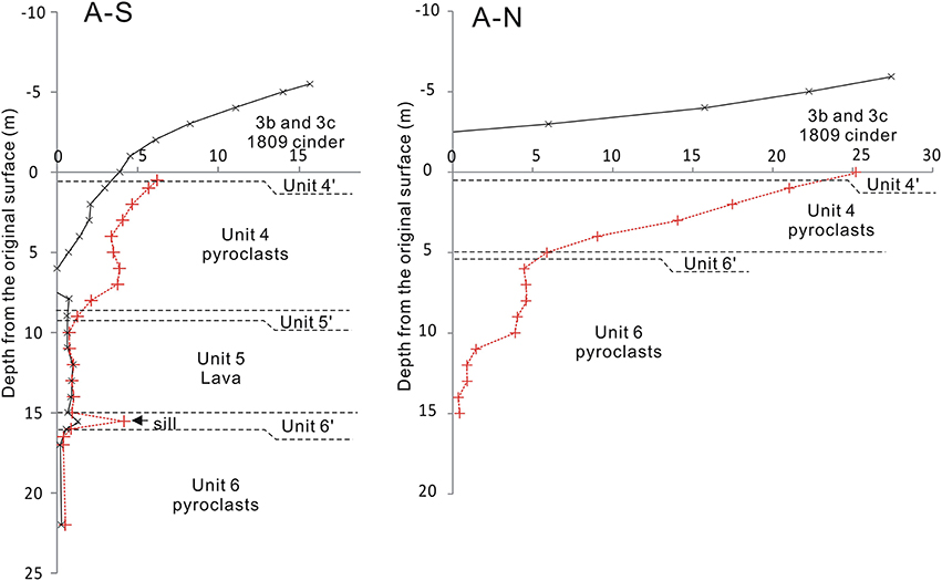
Figure 7. Variations of the width of the feeder system in the southern (A–S) and northern (A–N) walls of the 1809 crater A. Red lines and symbols show the width of the feeder. Black lines show the shape of the crater and the cavity in the dyke.
The feeder system in the outcrop A–N increases its thickness from ~0.5 m at the deepest portion to ~25 m at the original ground surface (Figure 7). The dyke thickness gradually increases between 15 and 10 m deep, then remains at 4–5 m between 10 and 5 m deep. The thickness increases rapidly toward the surface in Unit 4, within 5 m from the original ground surface.
Components of the Feeder System
The feeder system cropping out along the A–S section can be divided into marginal parts (rim) and inner parts (core) (Figure 8). The rim develops below 7.5 m from the original topographic surface, i.e., the ground level at the beginning of the 1809 eruption (see Figure 5). It develops continuously below 14 m from the original surface, whereas it is truncated in several parts between 7.5 and 14 m. The rim consists of coherent intrusive rock, without any significant evidence of fragmentation (Figures 8A,B). The vesicularity in the rim is 32–43%. The typical size of bubble ranges from 0.5 to 4 mm. The shape of bubbles is flat and elongated along the nearby dyke wall. On the dyke wall, the bubbles form sub–horizontal lineaments (~10°dipping to South).
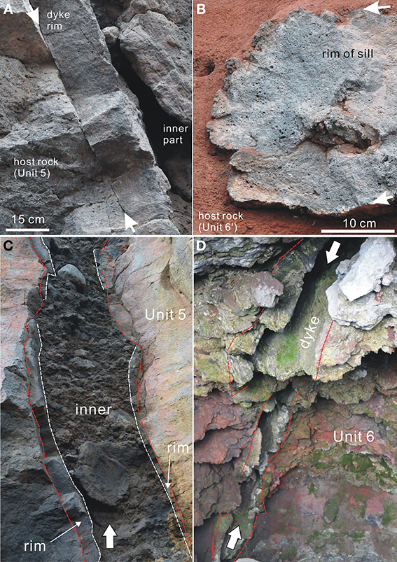
Figure 8. Marginal portion of the feeder in the outcrop A–S (A and B). (A) The dyke margin along the eastern wall of the feeder ~14 m below the original ground surface. (B) The eastern tip of the sill. Arrows indicate the intrusive surface of the dyke and sill. Cavities in the center of the feeder dyke (C,D). White arrows indicate the cavities. (C) The cavity filled with the breccia in the southern wall (outcrop A–S), (D) cavity at the center of the feeder dyke ~20 m from the original ground surface (outcrop A–S).
The inner parts are filled with pyroclastic materials (basaltic bombs, lithic blocks and finer volcanic sand and ash). Interstices of the blocks are partially filled with lapilli and sands, which show sub–horizontal bedding (Figure 8C). Some hollows and empty spaces are also found in the inner part (Figure 8D).
The feeder dyke at the base of the outcrop A–N consists of coherent intrusive rock, without any clear evidence of fragmentation. The upward–flaring part within 15 m from the original ground surface is filled with pyroclastics.
In outcrops B–N and B–S, all the exposed parts of the feeder consist of diatreme filled with pyroclastic materials. The transition between dyke and diatreme is not exposed.
Sill
The sill developing in Unit 6′ crops out only on the walls of crater A–S. It exhibits a lens–like shape (4.5 m in length along the horizontal section) and a maximum thickness of 0.6 m (Figure 9A). Both edges of the sill show rounded shape inflating toward the surrounding volcanic ash layer. The sill also consists of a marginal and inner part. The marginal part consists of coherent intrusive rock with relatively high vesicularity (49–53%). The typical size of bubble ranges from 0.5 to 6 mm. The shape of bubbles is flat and elongated sub–parallel to the outline of the sill. The bubbles also show the oblique alignment against the nearby wall of the sill (Figure 9B).
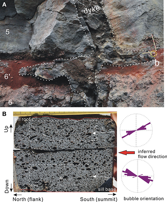
Figure 9. View of the sill of the feeder system cropping out along the southern wall of the 1809 crater A (outcrop A–S). (A) The close up view of a sill developing in Unit 6. Outline of the dyke and sill is shown by white dotted lines. Yellow circle shows the position of the sample for the analysis of preferred orientation of bubbles. (B) The vertical cross section of the sill along the strike of the feeder system. Distributions of the bubble elongation in upper and lower part of the section are shown on right. Boxes with dashed line show the area for the bubble orientation.
Size of the Feeder System
The horizontal width of the feeder system is larger at the original topographic surface, due to its upward–flaring shape in each cross section (Figures 3, 5, 7). The width of the feeder is larger (~30 m) at the outcrop B–S (Crater B, see Figure 2), located at the center of the segment of the eruptive fissure here examined (~450 m in length, between 2440 and 2260 m asl), and decreases toward both ends of the structural segment (Figure 10A). At the base of each outcrop the dyke thickness is almost constant, varying from 0.4 m (A–N and B) and 0.5 m (A–S).
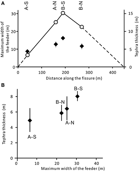
Figure 10. (A) Distribution of the maximum width of the feeder at the original ground surface (scale on left) and the thickness of the scoriaceous tephra at the crater (A and B) margin (scale on right). Distance is measured along the eruptive fissure 3 from its southern edge. (B) Thickness of the scoriaceous tephra at the crater (A and B) margin plotted against the width of the feeder at the original ground surface.
The thickness of Unit 3b and 3c, which represent the magmatic products of the fissure in the first half of the eruption, is also greater at the outcrop B–S and then decreases toward A–S and B–N in the margins of the eruptive fissure. The width of the feeder correlates with the thickness of the scoriaceous tephra (Unit 3b and c) at the rim of the feeder (Figure 10B).
Discussion
Growth Process of the Feeder System
The propagation of the eruption fissure during the 1809 eruption indicates the dyke was fed from the shallow portion of the central conduit beneath the summit Central Crater (Figure 1A) and intruded horizontally along the northern rift zone, as also occurred during the recent flank eruptions in the NE Rift (Garduño et al., 1997; Andronico et al., 2005; Neri et al., 2011). The strike (toward NNE) and dip (subvertical) of the feeder observed in the outcrops of the craters A and B reflect the entire structure of the feeding system in the NE Rift zone. The preferred orientation of the bubbles in the feeder dyke (Figure 9B) indicates the sub–horizontal movement of the magma in the shallow portion, which is consistent with the outward and centrifugal propagation of the eruptive fissure.
During the approach to the topographic surface, the feeder dyke was temporally halted and deflected at the base of the lava layer (Unit 5; see stage 2 in Figure 11). As the overlying Unit 5 consisting of massive lava has greater stiffness than the underlying scoriaceous deposit, this mechanical discontinuity acts as a temporary mechanical barrier for the dyke propagation (Gudmundsson, 2006, 2011). On increasing the internal magmatic pressure, the blocked dyke intruded along the base of Unit 5 and formed a small sill (Figures 5, 9A, 11).
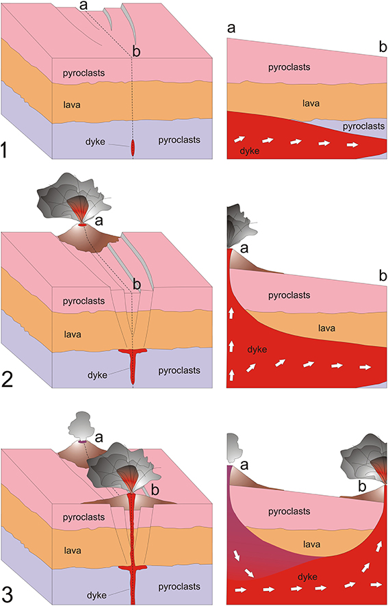
Figure 11. Evolution of the central portion of the 1809 eruptive fissure system (~2350 m elevation asl). Stage 1: the eruptive fissure propagated from the Central Crater of Mt. Etna into the NE Rift; the dyke propagated at shallow level forming a graben–like structure at the surface. Stage 2: the dyke met the lava layer creating a small temporary sill, while part of the graben (at higher elevation) becomes eruptive. Stage 3: the dyke progressively propagated downslope, passing the lava layer and forming a new vent.
The vertical dyke re-injected from the sill into the overlying Unit 5 when the internal magmatic pressure became high enough to break the overlying Unit 5 (stage 3 in Figure 11). The re-propagation of the dyke into the overlying layer caused a drop in the internal excess pressure of the dyke and, consequently may have stopped the horizontal growth of the sill. The development of the feeder parallel to the joints system developing in Unit 5 (Figure 5) suggests that the dyke intruded along a pre-existing fracture in Unit 5. The inclined propagation of the uppermost part of the dyke caused the oblique eruption that formed an asymmetric scoria cone around the crater (Unit 3b, c, and d).
Fragmentation in the Conduit
The texture of the components of the feeder system and the ejecta indicates the fragmentation of magma started the moment the vent opened. The feeder dyke was temporarily halted and formed a sill at the base of Unit 5 before reaching the surface (Figure 12, stage 2). Therefore, the cooled margin at the tip of the sill is a trapped magma which preserves the texture of magma before the eruption. The cooled margin consists of coherent intrusive rock without any evidence of fragmentation (Figure 8B). This suggests that the magma intruded the very shallow part without fragmentation. High vesicularity in the cooled margin indicates that the ascending magma reached high bubble–content before the vent opening. The existence of the coherent dyke margin up to 7.5 m from the original topographic surface indicates that the magma reached the surface within 10 m in fluid form (non-fragmented) before the opening of the vent. On the contrary, all the products cropping out at the rim of the crater (Unit 3b) are pyroclasts (basaltic spatters and welded breccia) and no lava flow was formed (Figure 4). This means that magma reaching the ground surface was already fragmented and erupted as a spatter from the onset of the eruption. This also implies that the fragmentation in the conduit started the moment the vent opened at the surface.
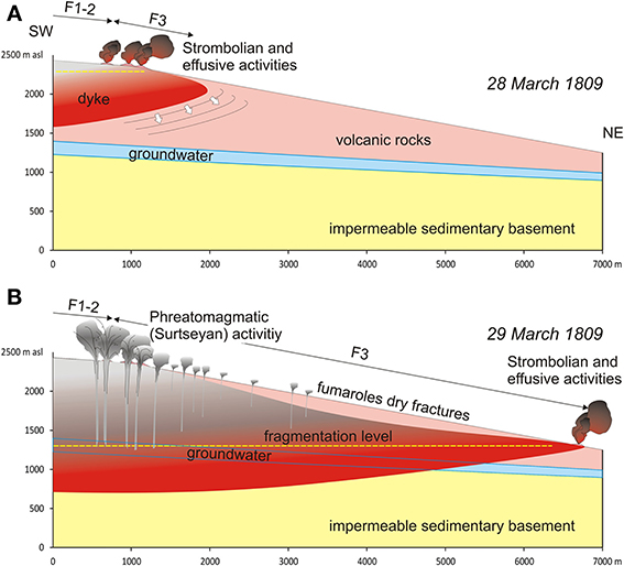
Figure 12. Model of dyke propagation of the 1809 eruption, between 2500 and 1300 m asl. On 28 March, the dyke from the Central Crater (~3200 m asl) propagates downslope (A), erupting at the lower portion of the fracture field (F1–3); at this stage the dyke is too shallow to involve the groundwater. On 29 March, the dyke propagates downslope reaching a minimum elevation of 1450–1325 m asl (B), where a new explosive and effusive vent formed. During the propagation, the dyke became deeper and magma interacted with the groundwater when the fragmentation level was roughly at the same elevation as the aquifer, generating phreatomagmatic (Surtseyan) activity along the higher portion of Fissure 3. It cannot be excluded that other shallower aquifers interacted with the dyke during its deepening and propagation downward. The position of the impermeable sedimentary basement is modified from Siniscalchi et al. (2012).
The fragmentation of the magma can be caused by rapid decompression in the conduit by the opening of vent at the surface (e.g., Alidibirov and Dingwell, 1996). Rapid decompression accelerates magma ascent and may cause strain–induced fragmentation (e.g., Papale, 1998). Formation of the sill at the base of the stiff layer (lavas of Unit 5) indicates that magma had a certain excess pressure before the arrival of the dyke at the surface (Gudmundsson, 2011). Release of the pressurized magma at the ground surface caused an explosive emission of magma.
The ejection speed of the pyroclastic clasts represents the rising speed of magma at the vent. This ejection speed can be evaluated from the incline angle of the conduit and from the distribution of the ejecta, assuming the ballistic flight of the volcanic bombs. The relationship between the inclination of the conduit (75° toward East) and the maximum thickness of the ejecta (Unit 4b) at ~80 m from the eruption site indicates the mean ejection speed at ~40 ms−1, neglecting the air resistance and slope of the ground. The ascent speed before the vent opening is typically several ms−1 judging from the typical propagation speed of the eruption fissure at the NE Rift (Neri et al., 2011, and references therein). This implies that the magma ascent rate accelerated at the opening of the vent and this acceleration triggered the explosive emission of fragmented magma.
Erosion of the Wall of the Feeder System
The upward–flaring shape of the feeder observed in the eruptive system of the 1809 eruption is commonly observed in explosive feeder systems (e.g., Keating et al., 2008; Geshi and Oikawa, 2014). The width of the feeder and the size of the eruptive crater at the surface are determined by the shape of the uppermost part of the feeder. Several mechanisms are proposed for the formation of upward flaring feeder systems (e.g., Valentine and Groves, 1996). Among them, erosion from particle collision and conduit wall collapse due to variations in magma pressure and/or shock waves are possible prime mechanisms for the feeders of the 1809 eruption, judging from the variation of width of the feeder reflected in the host rock lithofacies (Figure 8). In the outcrop A–S, the feeder begins increasing in width ~15 m deep from the original ground surface. The rapid increase of the width from the boundary between Unit 5 (lava) and overlying Unit 4 (pyroclasts) suggests that the feeder was enlarged particularly in the less consolidated host rock, since the mechanical erosion processes, such as particle collision and wall collapse, are more effective in the less consolidated host materials.
The positive correlation between the width of feeder system and the thickness of the tephra erupted (Figure 9B) also suggests the vigorous mechanical erosion by particle collision and wall collapse during the explosive emission of tephra. The greatest thickness of tephra at A–N and B–S outcrops indicates the larger magma flux at the center of the segment. The feeder was widened by the vigorous emission of pyroclastic materials during the fissure eruption. Conversely, the widening by the erosion was less effective in the peripheral zone (Figure 10A).
Drain–Back in the Later Stage of the Eruptive Fissures Propagation
The existence of a partially–filled hollow at the center of the feeder (Figures 8C,D) and the change in eruption style recorded in chronicles and manifested in the erupted products (Figure 4), suggest the withdrawal of magma from the erupting conduit and the abrupt termination of the eruption in the zone of the craters A and B (Figure 12). The change of eruption style is testified by the erupted products exposed along the walls of the craters A (Figure 4) and B. The eruption style changed from the oblique lava fountaining, which produced Unit 3b and 3c, to the explosive activities and crater enlargements that formed the lithic–rich Unit 3d. The eruptive vent exposed at the outcrop A–S is covered with Unit 3d (Figure 5). This suggests that the eruption was terminated by the withdrawal of magma, as also testified by the feeder outcrop in A–S.
According to the historical chronicles (Gemmellaro, 1860), the propagation of the eruptive fracture system lasted about two days, from March 27 to 29, but the final step of this migration (from ~2400 to ~1400 m asl) occurred in a few hours, covering a distance of ~5500 m. Therefore, this migration lowered the eruptive vents by about 1000 meters with respect to the craters A and B (see Figure 12). This dramatic and sudden drop in the level of the magma would have brought the magma into contact with the main groundwater contained in the volcanic body, which is located just above the contact surface between the volcanic pile and its impermeable (clay–rich) basement. In the central zone of the NE Rift, the impermeable basement is at ~1200–1300 m asl (Branca and Ferrara, 2012; Siniscalchi et al., 2012). Therefore we assume the level of magma fragmentation may have interacted with the aquifer when the vents shifted from ~2400 to 1450–1325 m asl, generating phreatomagmatic (Surtseyan) activity along the higher portion of Fissure 3 (see Figure 12B). On the other hand, we cannot exclude that other shallow and discontinuous aquifers interacted with the magmatic dyke during its migration downward.
Similar magma–groundwater interactions were recently documented during the 2001 flank eruption on the southern slope of Mt. Etna (Behncke and Neri, 2003b; Calvari and Pinkerton, 2004), when the 2570 m eccentric vent was the site of powerful phreatomagmatic activity as the dyke cut through a shallow aquifer. This phenomenon did not occur during the 2002–2003 flank eruption, which affected the NE Rift (Andronico et al., 2005). In this case, the eruptive fractures propagated from the NE Crater area (~3300 m) downward to ~1800 asl, i.e., the magmatic dyke did not migrate deep enough to interact with the groundwater. Yet, eruptions of this type – rapid propagation of unusually long eruptive fissure systems – have occurred at Etna a few times per century, most recently in 1923, 1928, and 1981 (Acocella and Neri, 2003; Neri et al., 2011).
Scenarios where dykes show various types of interaction with aquifers can be envisaged in many basaltic volcanic settings worldwide, ranging from monogenic volcanic fields as Auckland (New Zealand) to large polygenic volcanoes, including the Hawaiian shield volcanoes. In particular, the rapid propagation and drainage of a dyke, as in the case of Etna's 1809 eruption, represents a potential hazard because of the enhanced possibility of a sudden and unexpected magma–groundwater interaction. Phreatomagmatic activity not only represents a threat to people within a certain distance from the eruptive vents, but it is also capable of producing abundant quantities of volcanic ash, which would affect much wider areas and potentially disrupt air traffic.
Conclusions
The 1809 eruption of Mt. Etna is fairly typical of the flank eruptions occurring along the NE Rift, but with a fundamental difference: the development of the fracture field was characterized, in its central sector, by an abrupt change in eruptive style, testified by the outcrops exposed along the inner walls of some craters. In addition, the eruptive style characterizing the final part of the eruptive activity of these craters resulted in an unusually but clear exposure of the shallow feeder system. This is therefore a highly important case to understand just how basaltic magmas evolve and move during the propagation of an eruptive fissure.
Based on the results of this study, it is evident that the amplitude of the feeder system at shallow levels is affected by the lithology of the host rock. The dyke is some tens of centimeters thick when it crosses compact rocks such as lava, but widens up to several meters in portions contained by non–welded pyroclastic products, in this second case easily erodible. In addition, the contact between pyroclasts (below) and lavas (above) creates favorable conditions for the development of small sills.
The transition between the initial effusive/Strombolian phase to a more explosive phreatomagmatic one created the formation of cavities in the feeder system. Phreatomagmatic activity was probably triggered by the interaction between the magma and the aquifer of the volcano, just when magma migrated abruptly downwards. During this last activity, the dyke was no longer only formed by compact lava but contained unconsolidated scoriaceous breccia and fragmented lavas.
Due to the rapid withdrawal of magma in the feeder system, which dropped by about 1000 m in altitude, the walls of the feeder were no longer sustained by the magma, so they partially collapsed (at shallow levels), facilitating the formation of the two large pit craters A and B during the final stage of the propagation of the eruptive fissures.
The understanding of these mechanisms sheds new light on (a) the propagation mechanism of eruptive fractures in basaltic volcanoes such as Mt. Etna, (b) how magma moves inside the feeder systems and (c) how the dynamic of the magma creates conditions of variability of eruptive styles during the same eruption. These results are also useful in terms of hazard assessment, since they allow predicting different eruptive scenarios according to the dynamics of the structural system feeding the eruptions, a crucial factor in highly urbanized volcanoes. These results would in particular be helpful for the production of detailed maps showing the probability of the opening of new vents and the simulation of lava flows, which is of particular relevance in areas of basaltic volcanism that are subjected to rapid urban expansion.
Conflict of Interest Statement
The authors declare that the research was conducted in the absence of any commercial or financial relationships that could be construed as a potential conflict of interest.
References
Acocella, V., Behncke, B., Neri, M., and D'Amico, S. (2003). Link between major flank slip and eruptions at Mt. Etna (Italy). Geophys. Res. Lett. 30:2286. doi: 10.1029/2003GL018642
Acocella, V., and Neri, M. (2003). What makes flank eruptions?: the 2001 Etna eruption and the possible triggering mechanisms. Bull. Volcanol. 65, 517–529. doi: 10.1007/s00445-003-0280-3
Acocella, V., Neri, M., and Scarlato, P. (2006a). Understanding shallow magma emplacement at volcanoes: orthogonal feeder dikes during the 2002–2003 Stromboli (Italy) eruption. Geophys. Res. Lett. 33:L17310. doi: 10.1029/2006GL026862
Acocella, V., Neri, M., and Sulpizio, R. (2009). Dike propagation within active central volcanic edifices: constraints from Somma-Vesuvius, Etna and analogue models. Bull. Volcanol. 71, 219–223. doi: 10.1007/s00445-008-0258-2
Acocella, V., Porreca, M., Neri, M., Mattei, M., and Funiciello, R. (2006b). Fissure eruptions at Mount Vesuvius (Italy): insights on the shallow propagation of dikes at volcanoes. Geology 34, 673–676. doi: 10.1130/G22552.1
Alidibirov, M., and Dingwell, D. B. (1996). Magma fragmentation by rapid decompression. Nature 380, 146–148.
Allard, P., Behncke, B., D'Amico, S., Neri, M., and Gambino, S. (2006). Mount Etna 1993–2005: anatomy of an evolving eruptive cycle. Earth-Sci. Rev. 78, 85–114. doi: 10.1016/j.earscirev.2006.04.002
Andronico, D., Branca, S., Calvari, S., Burton, M. R., Caltabiano, T., Corsaro, R. A., et al. (2005). A multi-disciplinary study of the 2002–03 Etna eruption: insights for a complex plumbing system. Bull. Volcanol. 67, 314–330. doi: 10.1007/s00445-004-0372-8
Behncke, B., and Neri, M. (2003a). Cycles and trends in the recent eruptive behaviour of Mount Etna (Italy). Can. J. Earth Sci. 40, 1405–1411. doi: 10.1139/E03-052
Behncke, B., and Neri, M. (2003b). The July–August 2001 eruption of Mt. Etna (Sicily). Bull. Volcanol. 65, 461–476. doi: 10.1007/s00445-003-0274-1
Bonforte, A., Guglielmino, F., Coltelli, M., Ferretti, A., and Puglisi, G. (2011). Structural assessment of Mount Etna volcano from Permanent Scatterers analysis. Geochem. Geophys. Geosyst. 12:Q02002. doi: 10.1029/2010GC003213
Bousquet, J. C., and Lanzafame, G. (2001). Nouvelle interprétation des fractures des éruptionslatérales de l'Etna: conséquences pour son cadre tectonique. Bull. Soc. Géol. Fr. 172, 455–467. doi: 10.2113/172.4.455
Branca, S., Coltelli, M., Groppelli, G., and Lentini, F. (2011). Geological map of Etna volcano, 1:50,000 scale. Ital. J. Geosci. 130, 265–291. doi: 10.3301/IJG.2011.15
Branca, S., and Ferrara, V. (2012). The morphostructural setting of Mount Etna sedimentary basement (Italy): implications for the geometry and volume of the volcano and its flank instability. Tectonophysics 586, 46–64. doi: 10.1016/j.tecto.2012.11.011
Calvari, S., and Pinkerton, H. (2004). Birth, growth and morphologic evolution of the “Laghetto” cinder cone during the 2001 Etna eruption. J. Volcanol. Geotherm. Res. 132, 225–239. doi: 10.1016/S0377-0273(03)00347-0
Cappello, A., Neri, M., Acocella, V., Gallo, G., Vicari, A., and Del Negro, C. (2012). Spatial vent opening probability map of Mt. Etna volcano (Sicily, Italy). Bull. Volcanol. 74, 2083–2094. doi: 10.1007/s00445-012-0647-4
Del Negro, C., Cappello, A., Neri, M., Bilotta, G., Hérault, A., and Ganci, G. (2013). Lava flow hazards at Etna volcano: constraints imposed by eruptive history and numerical simulations, Scientific Reports. Nature 3:3493. doi: 10.1038/srep03493
Garduño, V. H., Neri, M., Pasquarè, G., Borgia, A., and Tibaldi, A. (1997). Geology of the NE Rift of Mount Etna, Sicily (Italy). Acta Vulcanol. 9, 91–100.
Gemmellaro, C. (1860). La vulcanologia dell'Etna. Atti Acc. Gioenia Sc. Nat., Ser. II, vol.14-15, p.131-133 Catania.
Geshi, N., Kusumoto, S., and Gudmundsson, A. (2010). The geometric difference between non-feeders and feeder dikes. Geology 38, 195–198. doi: 10.1130/G30350.1
Geshi, N., and Oikawa, T. (2014). The spectrum of basaltic feeder systems from effusive lava eruption to explosive eruption at Miyakejima volcano, Japan. Bull. Volcanol. 76, 797. doi: 10.1007/s00445-014-0797-7
Gudmundsson, A. (1987). Lateral magma flow, caldera collapse and a mechanism of large eruptions in Iceland. J. Volcanol. Geotherm. Res. 34, 65–78.
Gudmundsson, A. (2006). How local stresses control magma-chamber ruptures, dyke injections, and eruptions in composite volcanoes. Earth Sci. Rev. 79, 1–31. doi: 10.1016/j.earscirerv.2006.06.006
Gudmundsson, A. (2011). Deflection of dykes into sills at discontinuities and magma-chamber formation. Tectonophysics 500, 50–64. doi: 10.1016/j.tecto.2009.10.015
Gudmundsson, A., Oskarsson, N., Gronvold, K., Saemundsson, K., Sigurdsson, O., Stefansson, R., et al. (1992). The 1991 eruption of Hekla, Iceland. Bull. Volcanol. 54, 238–246.
Keating, G. N., Valentine, G. A., Krier, D. J., and Perry, F. V. (2008). Shallow plumbing system for small-volume basaltic volcanoes. Bull. Volcanol. 70, 563–582 doi: 10.1007/s00445-007-0154-1
Komorowski, J. C., Tedesco, D., Kasereka, M., Allard, P., Papale, P., Vaselli, O., et al. (2002). The January 2002 flank eruption of Nyiragongo volcano (DRC): chronology, evidence for a tectonic rift trigger and impact of lava flows on the city of Goma. Acta Vulcanol. 14, 25–57.
Lanzafame, G., Leonardi, A., Neri, M., and Rust, D. (1997). Late overthrust of the Appenine - Maghrebian Chain at the NE periphery of Mt. Etna, Sicily. C. R. Acad. Sci. Paris t.324, serie II a, 325–332.
McGuire, W. J., and Pullen, A. D. (1989). Location and orientation of eruptive fissures and feeder-dykes at Mount Etna: influence of gravitational and regional stress regimes. J. Volcanol. Geotherm. Res. 38, 325–244.
Neri, M., and Acocella, V. (2006). The 2004–05 Etna eruption: implications for flank deformation and structural behaviour of the volcano. J. Volcanol. Geotherm. Res. 158, 195–206. doi: 10.1016/j.jvolgeores.2006.04.022
Neri, M., Acocella, V., and Behncke, B. (2004). The role of the Pernicana Fault System in the spreading of Mount Etna (Italy) during the 2002–2003 eruption. Bull. Volcanol. 66, 417–430. doi: 10.1007/s00445-003-0322-x
Neri, M., Acocella, V., Behncke, B., Giammanco, S., Mazzarini, F., and Rust, D. (2011). Structural analysis of the eruptive fissures at Mount Etna (Italy). Ann. Geophys. 54, 464–479. doi: 10.4401/ag-5332
Neri, M., Lanzafame, G., and Acocella, V. (2008). Dike emplacement and related hazard in volcanoes with sector collapse: the 2007 Stromboli eruption. J. Geol. Soc. London 165, 883–886. doi: 10.1144/0016-76492008-002
Rubin, A. M., and Pollard, D. D. (1987). Origins of blade-like dikes in volcanic rift zones. US Geol. Surv. Prof. Pap. 1350, 1449–1470.
Ruch, J., Acocella, V., Storti, F., Neri, M., Pepe, S., Solaro, G., et al. (2010). Detachment depth of an unstable volcano revealed by rollover deformation: an integrated approach at Mt. Etna. Geophys. Res. Lett. 37:L16304. doi: 10.1029/2010GL044131
Ruch, J., Pepe, S., Casu, F., Acocella, V., Neri, M., Solaro, G., et al. (2012). How do rift zones relate to volcano flank instability? Evidence from collapsing rifts at Etna. Geophys. Res. Lett. 39:L20311. doi: 10.1029/2012GL053683
Ruch, J., Pepe, S., Casu, F., Solaro, G., Pepe, A., Acocella, V., et al. (2013). Seismo-tectonic behavior of the Pernicana Fault System (Mt Etna): a gauge for volcano flank instability? J. Geophys. Res. Solid Earth 118, 4398–4409. doi: 10.1002/jgrb.50281
Siniscalchi, A., Tripaldi, S., Neri, M., Balasco, M., Romano, G., Ruch, J., et al. (2012). Flank instability structure of Mt Etna inferred by a magnetotelluric survey. J. Geophys. Res. 117:B03216. doi: 10.1029/2011JB008657
Solaro, G., Acocella, V., Pepe, S., Ruch, J., Neri, M., and Sansosti, E. (2010). Anatomy of an unstable volcano through InSAR data: multiple processes affecting flank instability at Mt. Etna in 1994–2008. J. Geophys. Res. 115:B10405. doi: 10.1029/2009JB000820
Soriano, C., Beamud, E., and Garcés, M. (2008). Magma flowing dikes from rift zones of the basaltic shield of Tenerife, Canary Islands: implications for the emplacement of buoyant magma. J. Volcanol. Geotherm. Res. 173, 55–68. doi: 10.1016/j.jvolgeores.2008.01.007
Tedesco, D., Vaselli, O., Papale, P., Carn, S. A., Voltaggio, M., Sawyer, G. M., et al. (2007). January 2002 volcano-tectonic eruption of Nyiragongo volcano, Democratic Republic of Congo. J. Geophys. Res. 112:B09202. doi: 10.1029/2006JB004762
Keywords: feeder dyke, basaltic volcanoes, flank eruptions, Etna, volcanic hazards, sill, volcanic rift
Citation: Geshi N and Neri M (2014) Dynamic feeder dyke systems in basaltic volcanoes: the exceptional example of the 1809 Etna eruption (Italy). Front. Earth Sci. 2:13. doi: 10.3389/feart.2014.00013
Received: 21 March 2014; Paper pending published: 25 April 2014;
Accepted: 19 June 2014; Published online: 21 July 2014.
Edited by:
Agust Gudmundsson, Royal Holloway University of London, UKReviewed by:
Paraskevi Nomikou, University of Athens, GreeceJulie Roberge, ESIA-Ticoman Instituto Politecnico Nacional, Mexico
Copyright © 2014 Geshi and Neri. This is an open-access article distributed under the terms of the Creative Commons Attribution License (CC BY). The use, distribution or reproduction in other forums is permitted, provided the original author(s) or licensor are credited and that the original publication in this journal is cited, in accordance with accepted academic practice. No use, distribution or reproduction is permitted which does not comply with these terms.
*Correspondence: Marco Neri, Istituto Nazionale di Geofisica e Vulcanologia, Sezione di Catania, Osservatorio Etneo, Piazza Roma, 2, 95123 Catania, Italy e-mail: marco.neri@ct.ingv.it